Photo Realistic Rendering
1.Title of the Project:
“Design and Modelling of an American Chopper using Solidworks”
2.Objective:
To model and assemble the various components of American Chopper and perform photorealistic rendering using solidworks.
3. Introduction:
Solidworks is an effective and efficient modelling tool which are used globally. The user interface is very handy and helps to reduce the time consumption in modelling the complex designs and shapes. The design output provided by the solid works are more realistic and accurate. The components of the American chopper such as transmission belt, kickstand, fenders, wheels, chassis, Engine, Front fork chain, gas tank, oil tank, were modelled as per the dimensions. Further those components are assembled to generate complete model and also photorealistic rendering is performed using the solidworks CAD and Solidworks Visualize.
4.Design methodology/approach:
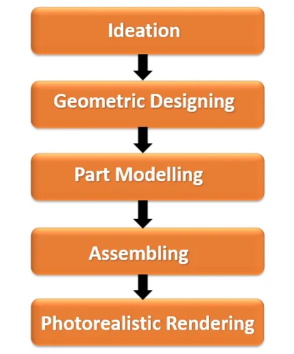
5. Description of Methodology:
- Ideation:
Ideation is the first stage of any designing process.in this stage by selecting any of the theme or venture thoughts are freeze, based on that idea various sketching, detailing of the component are generated using tools like photoshop or hand sketching. During this process several rough sketches are generated later those are refined to some extent in order to gather better design structured models. The ideation process depends upon individual perspective of the designer. therefore, it plays a vital role during designing stage.
- Geometric designing & Modelling:
- Transmission belt:
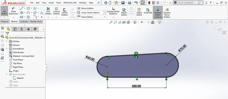
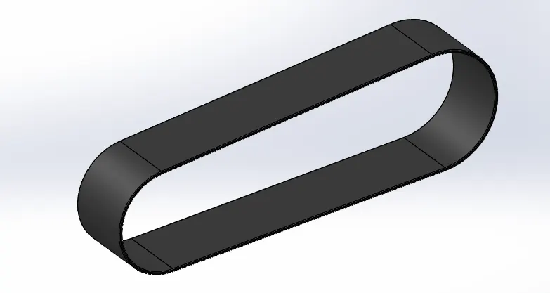
Design of Transmission belt
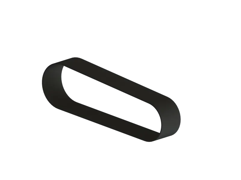
Transmission belt is a closed profile component which is aligned in between driven pulley and driver pulley. Initially a plane is selected and rough geometric outline sketching is created using line and circular features tools, further the constraints and relations are provided using smart dimensions and relation tools across the sketching.Using the boss/base feature tool extruding the sketch, and provide the fillets for edges. Applying the materials and appearances.
- Kick Stand:
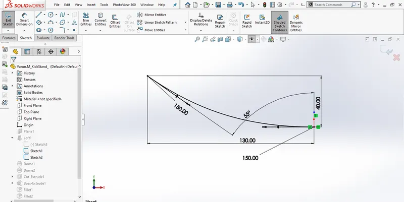
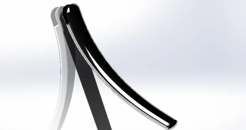
Design of Kick Stand
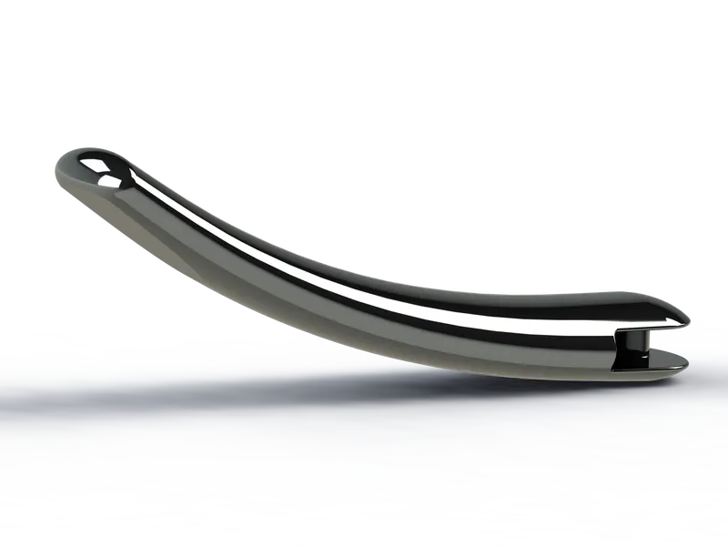
Kick stand is a curved profile component and it is aligned with the chassis. creating an elliptical profile in top plane using circular sketch tool with constraints and relations, another elliptical profile is created in its perpendicular plane. Using splines these two geometries are connected and a lofted boss tool option is used by giving the splines as guide drive. Domes are inserted at either of end surfaces and extruded cut is done at bottom surface of kick stand.
- Front and Rear Fenders:
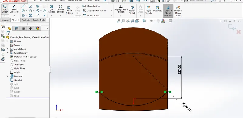
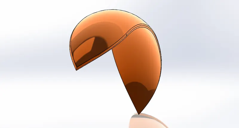
Design of Front and Rear fenders
Fenders are the curved profile shell components this align on top of the front and the rear wheels.Initially curved profile is sketched on the top plane and constraints, relations are provided using smart dimensions. Further off-setting the profile to create close defined sketch and revolved surface tool is used is by selecting axis line. Further splines are sketched on surface with the constraints and extruded cut is done to get desired shape finally making the shell for fender, providing fillets and applying appearance.
- Oil Tank & Gas tank:
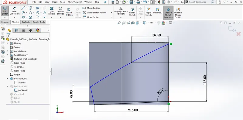
Design of Gas tank and Oil Tank
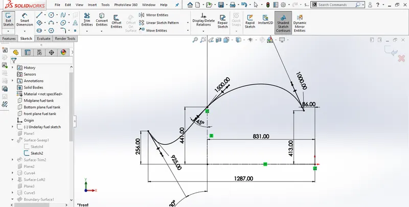
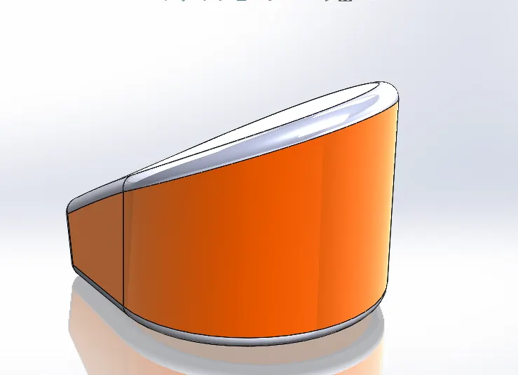
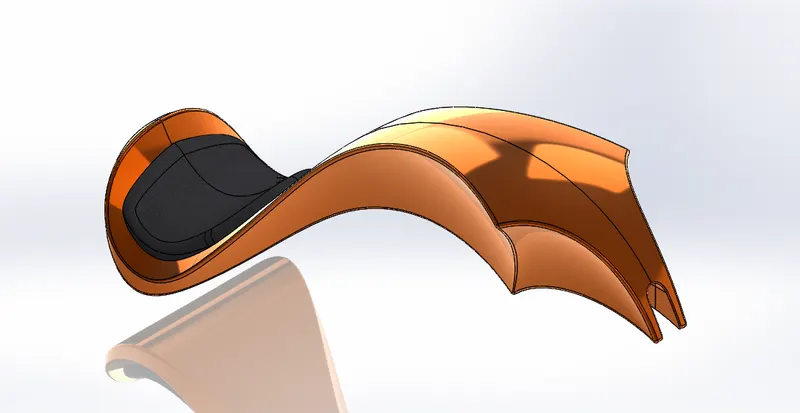
Oil Tank and Gas Tank is a shell profile component.Initially a plane is selected and the side profile of the tank is sketched using surface boss base the surface is created. Further by selecting right plane sketching is done later by using the projection curves the surface is generated. Later by using split tool extra material is removed from the body and fillet radius are given across the tank. selecting top surface seat is created using boss/base tool. finally using knit option all the surfaces were merged into a single body, and shell option is used to make hallow or a shell component for the gas tank.
- Front and Rear Wheels:
Design of Front and Rear Wheel
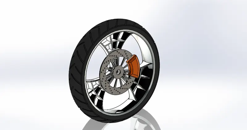
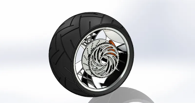
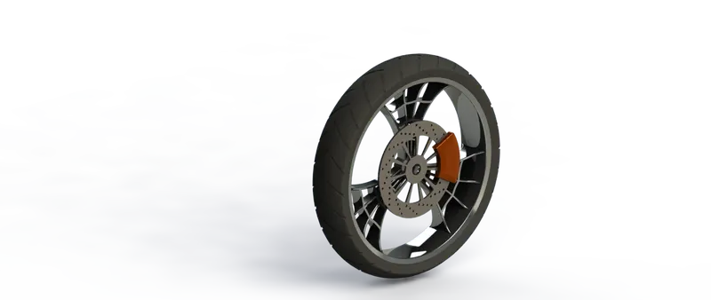
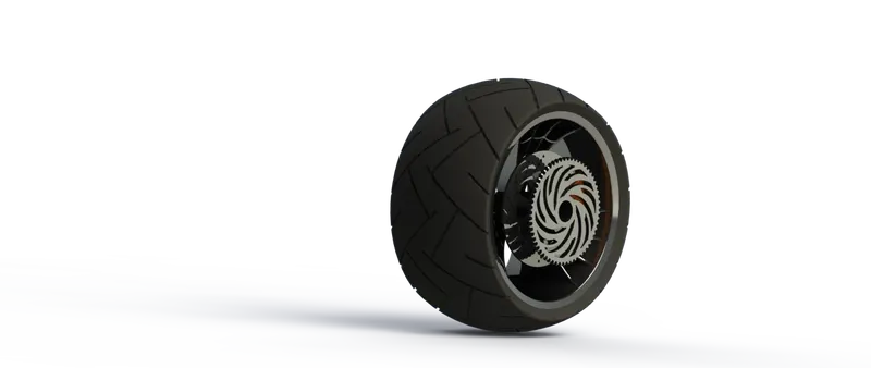
Front wheel is a circular type closed profile component, it is aligned between front fork and mounts on axle.Initially a plane is selected and rough geometric outline sketching is created using line and circular features, further the constraints and relations are provided across the sketching. Using the revolved boss/base feature extruding the sketch is done, further from front plane the spider web sketching is done and a cut-out tool used for performing cutout.tire profile is created and tread pattern is made on the tire using circular pattern and provide the fillets for edges. Applying the materials and appearances
- Pedal:
Design of Pedal
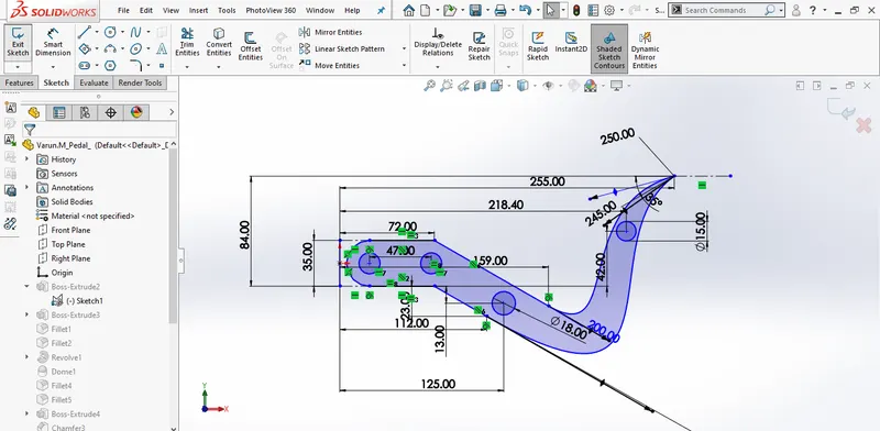
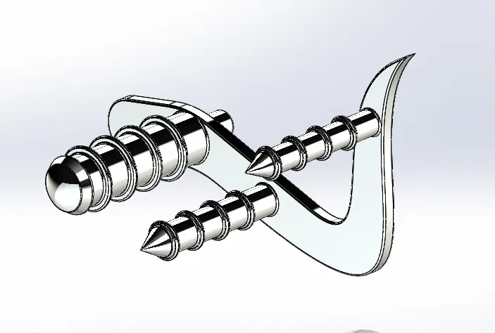
Pedal is a curved solid profile it is mounted on the chassis.By selecting the front plane the sketching is done using the line and splines.further the dimensions and reations are provided between the end points and extruded using boss/base tool.finally fillet radius are provided for all extrusions and edges and chamfering is done only on two extrusions.
- Chain:
Design of Chain
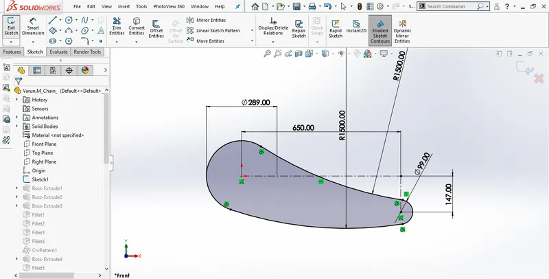
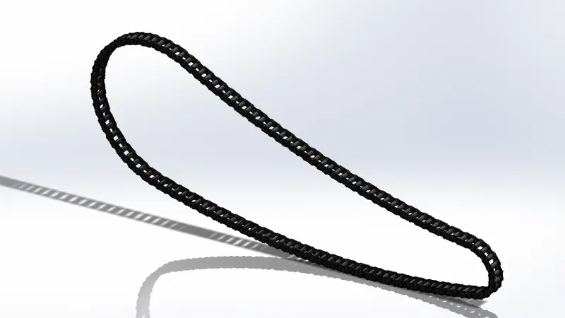
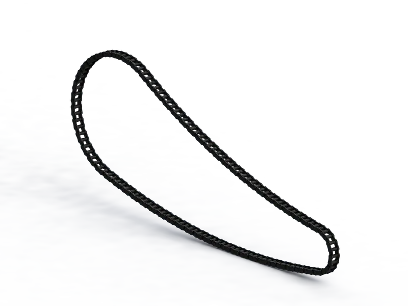
Chain is slotted link component.it is aligned on the pinion gear and sprocket.Initially the curve driven path of the chain is created based on the dimensions. Further the links, mounts, pins are sketched on the plane and relations are provided and extruded. Further these pins, links, mounts are made into two blocks. Finally, by using curve driven patten option the chain links, pins, mounts are aligned in the path exactly as of the dimensions provided
- Front Fork:
Design of Fork
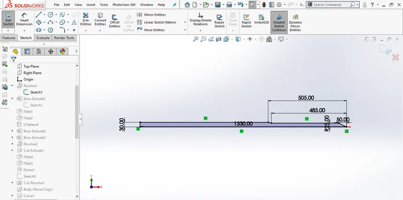
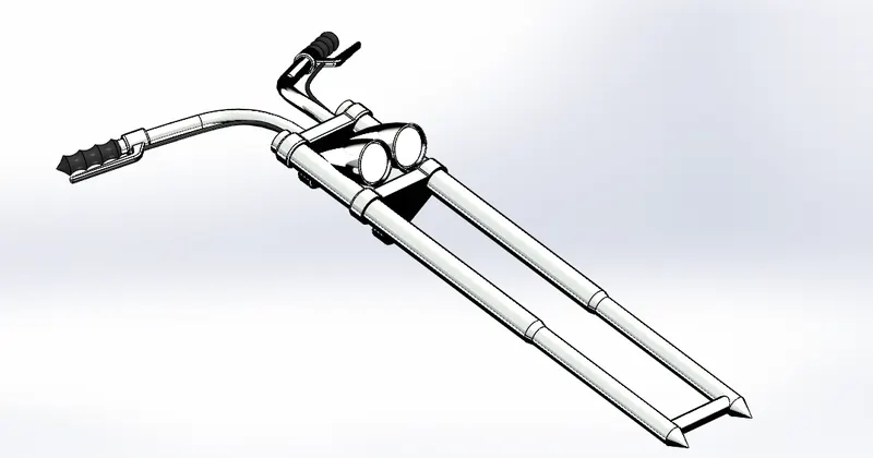
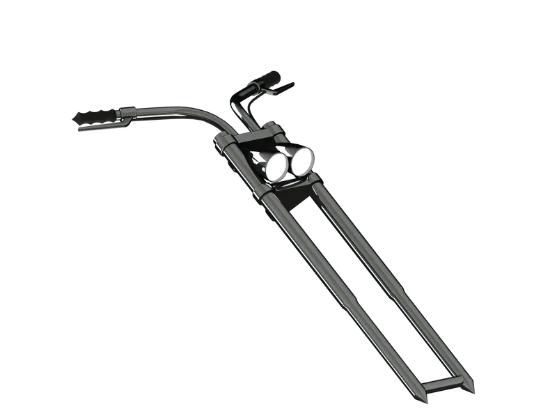
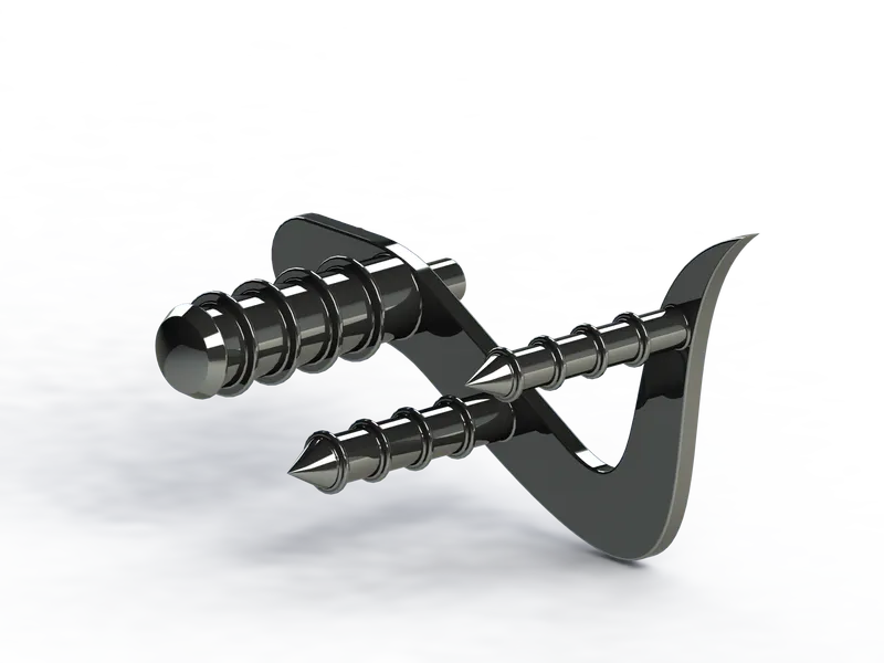
Front fork is a tubular profiled component,it is aligned to the chassis front structure.By selecting the midplane, the rough sketch of single fork is done further appropriate dimensions and relations are provide, later revolved boss/base is done. Further guide plates were modelled on the extreme end of fork. Later head light buckets were designed by creating a new plane. Further by making use of projection curves the handle bar is modelled. The cables are also designed using projection curves. Once the entire half model is built, by selecting the midplane mirroring is done which creates complete front fork.
- Chassis & Engine:
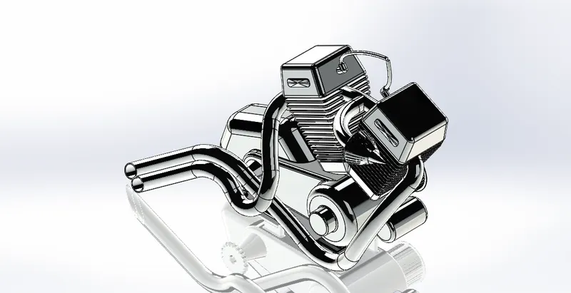
Design of Chassis and Engine
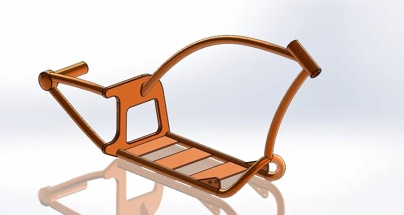
Chassis: is a tubular profile component.Initially a Midplane is selected and the chassis flow profile is sketched and respected dimensions and relations were provided. Further by selecting top plane tubular profile is sketched, by using sweep option chassis is generated later rear axle and pedal guide are modelled on the chassis, by using split option weld regions are made smoother in its transition. Finally for the rear mount plate fillet radius are provided.
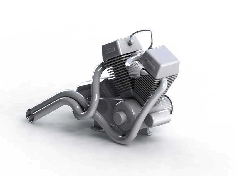
Engine: is component, it is mounted on the chassis rigidly.By selecting the Midplane the sketching of bottom circular profiles is done using the line and circles. Further the dimensions and relations are provided between the end points later extruded. Further by selecting top plane engine bore is generated by using linear pattern fins are generated. Later spark plugs, intake manifold, and air filter are modelled across the engine with appropriate dimensions. further the by using of projection curves and composition curves the tubular section mufflers are modelled for both the engine cylinders later for the base of the engine mounts are modelled. Finally fillet radius are provided for all extrusions.
- Assembly of American Chopper:
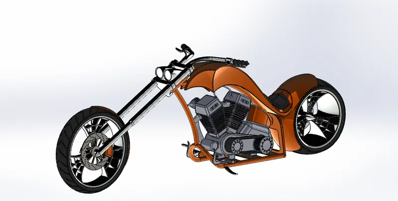
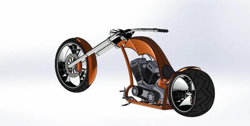
Camera 1 Camera 2
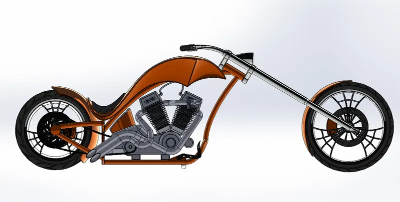
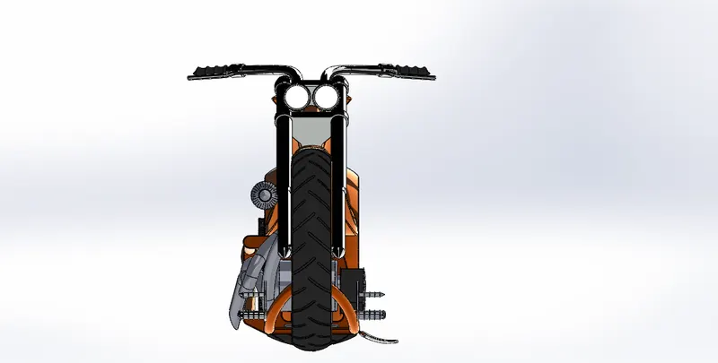
Side view Front view
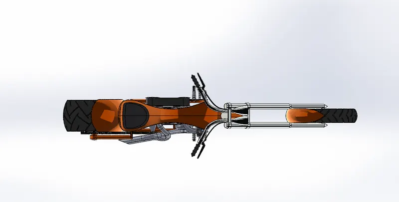
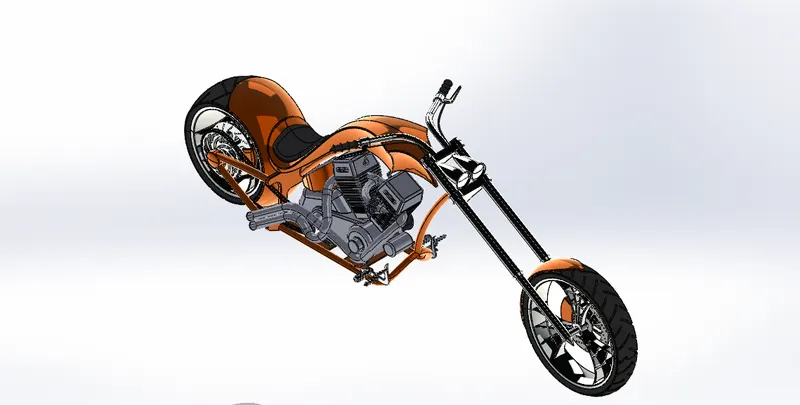
Top view Isometric view
Initially all the individual modelled components of chopper are brought into an assembly window, so that they were available instantly. first stage chassis is imported and by using appropriate mates the chassis made to place at midplane firmly. Further engine is imported and its base is made to fix on the top of chassis bed. Further rear wheel is imported and made to fit into axle of the chassis firmly using its concentricity and coincidence. Further chain is made to fit on the sprocket and on the pinion, gear using the width relation option. Later the transmission belt is imported and aligned between the two pulleys using width option and angular dimension mates. Later front fork is aligned to the chassis using its concentricity and front wheel and front fender is aligned exactly using the plane coincidence. Later rear fender is made to fit on the top of rear wheel exactly using the concentricity option. Further gas tank is made to fix on top of the chassis by using its midplane and top plane coincidence. Side stand is made to fix on the chassis mounts using its selected surface contacts and pedal is imported and assembled to the chassis firmly and it is mirrored on the other side by selecting the midplane. Later slight modifications were done to chassis, engine and the side stand to eliminate the interference between two components. And an angular movement is provided to the handle bar and the side stand so that it can tend to oscillate when it is turned by dragging the component. Once the entire assembly is done the chassis is made to float to check whether there are any flaws in component mates. Finally, again chassis is made to fix and saved as per the replica of provided design.
6. Rendering:
Photorealistic Rendering: ( Using Photoview 360):
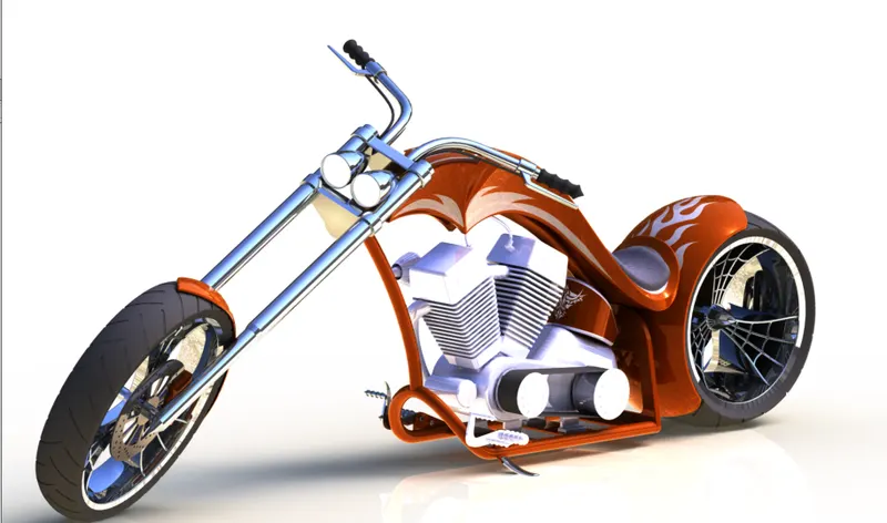
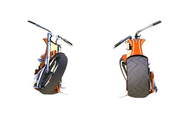
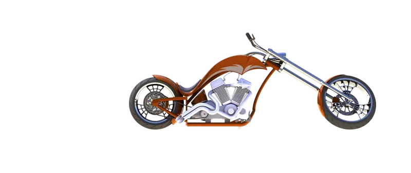
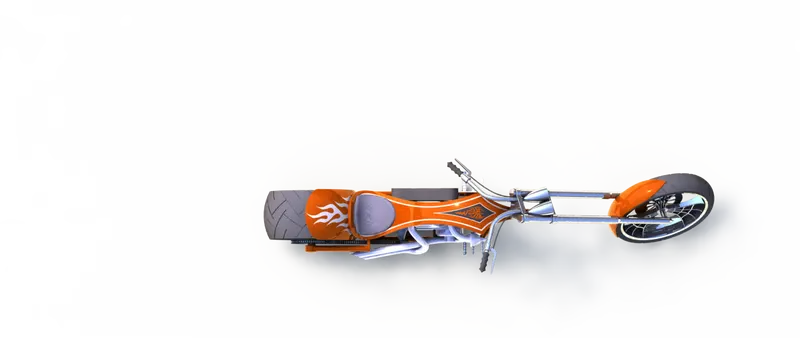
Rendered images of Chopper using Photoview 360 ( Camera1,front,rear,Side and top view )
Rendered Images of all components of American Chopper:
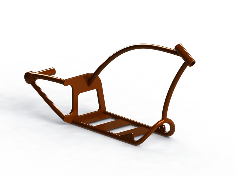
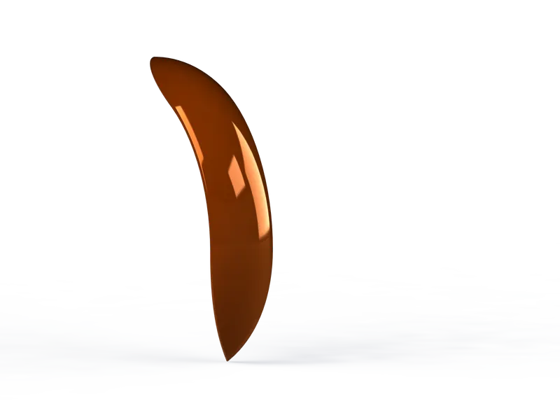
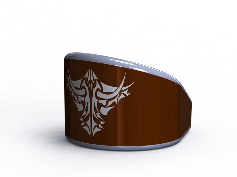
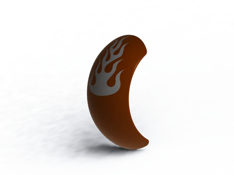
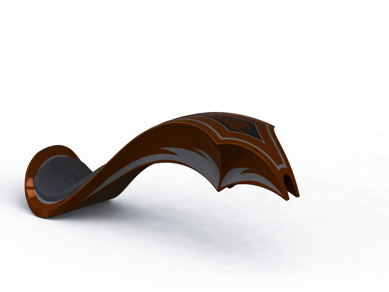
Photorealistic Rendering of American chopper : Using( Solidworks Visualize):
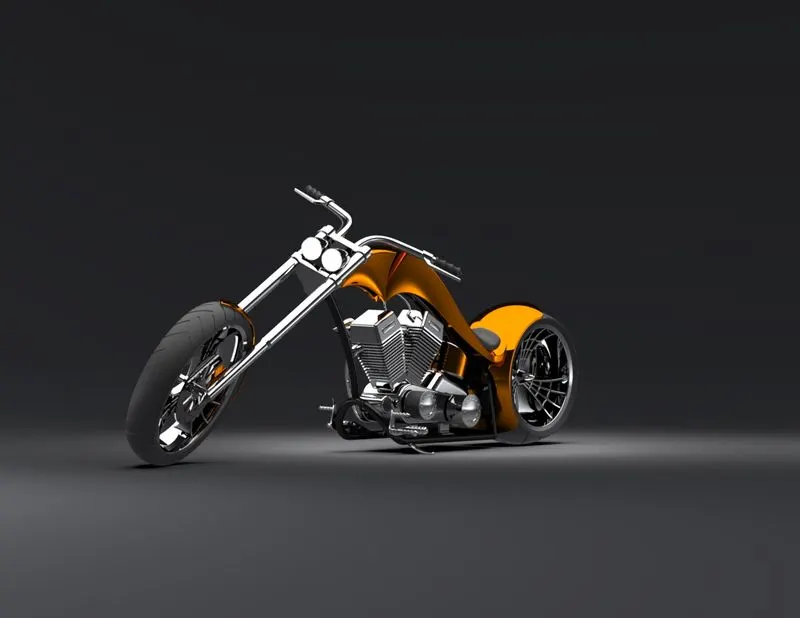
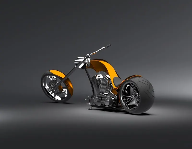
Renderd images at Classic Studio
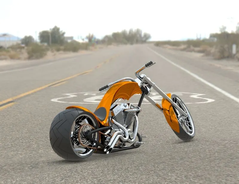
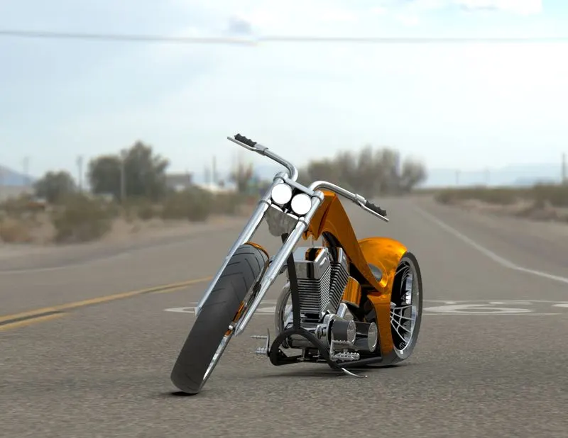
Renderd images at Route 66
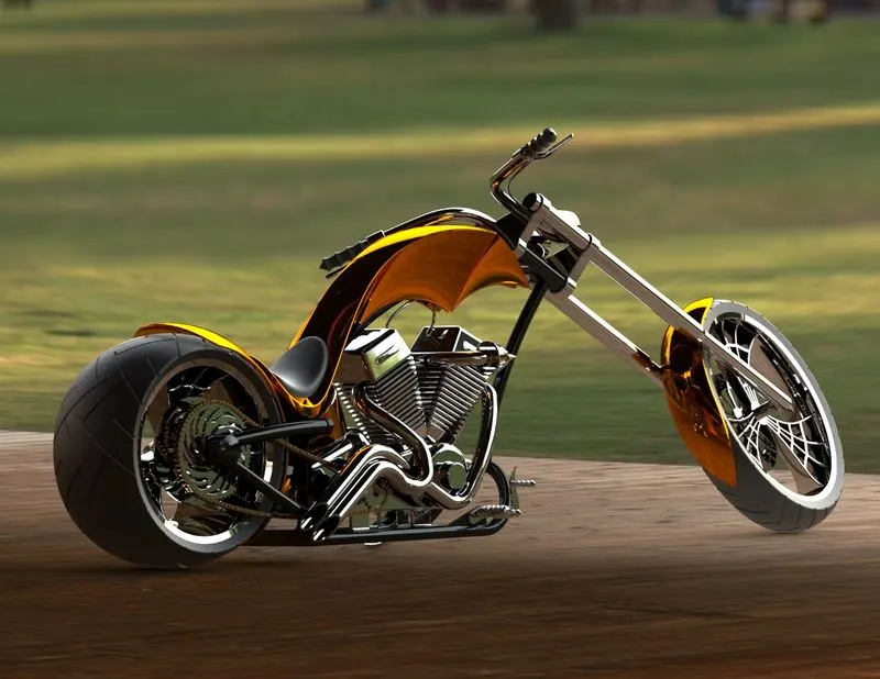
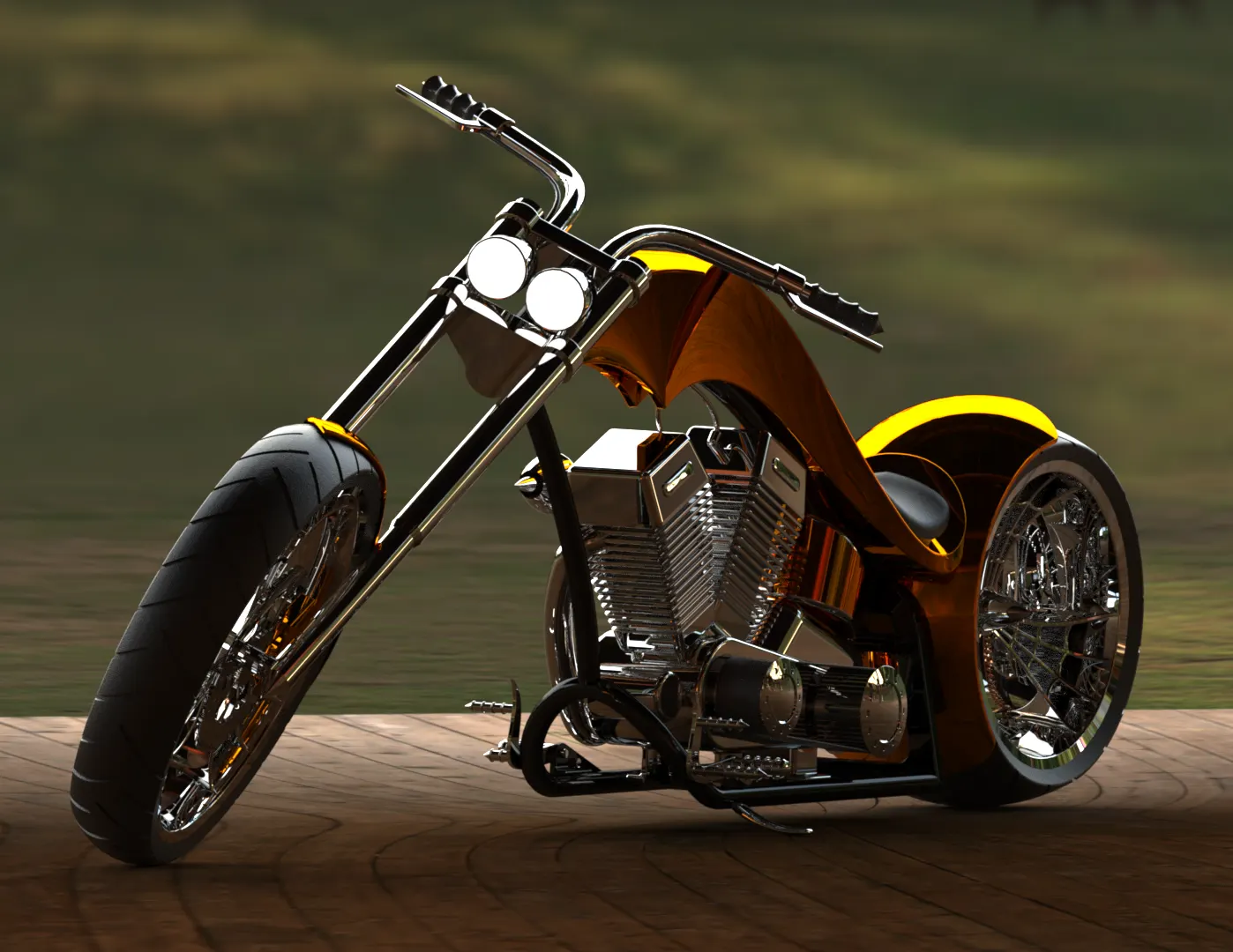
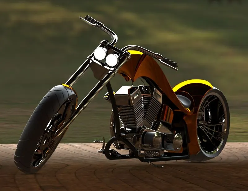
Renderd images at Wodden pellet
7. Conclusion
The components of American Chopper such as Transmission belt, Kickstand, Front and Rear fenders,chassis, chain,pedal,Front and rear wheels,gas and oil tank are modelled using Solidworks with appropriate dimensions and relations followed by the geometry.further an assembly of chopper is performed using those components and also phototrealistic rendering of chopper is done successfully.The output design of the modelled components represents, the exact replica of an actual 3D model components of American chopper.