Section Modulus calculation and optimization
- Title of the Project:
To Analyse the section modulus of the hood and perform design optimisation on hood using NX CAD 12.
- Objective:
To calculate the section modulus of the hood component and perform design optimisation, in order to increase their mechanical property using NX CAD 12.
- Section Modulus:
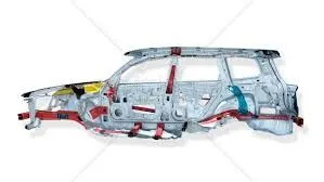
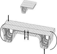
Section modulus is a geometric property of a given cross-section, that are used in design of beam or flexural members.it can also be defined as direct measure of strength of any sectional area of a component by its neutral axis.it is also known as torsional section modulus or polar modulus. Other geometrical properties that are used in design area for tension and shear, radius of gyration for compression, moment of inertia and polar moment of inertia for stiffness. This relationship between geometric properties is dependent on shape of the component.
The value of the section modulus will be same for both top and bottom of centroid of the cross section in symmetric cross-section, whereas in asymmetric sections consists of two values for top and bottom of the centroid.
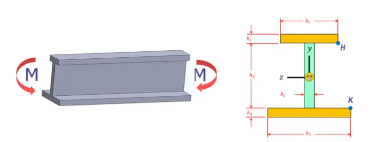
Section Modulus:
S=I/Y mm³
S=section modulus
I=moment of inertia mm⁴
Y=Distance from neutral axis mm
There are two types of section modulus and this section modulus formula varies based on their cross-section.
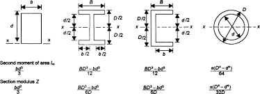
Elastic Section modulus:
For general design the elastic section modulus is used, applying up to the yield point for most metals and other common materials.
The elastic modulus is defined as S=I/Y where I is the second moment of inertia and Y is the distance from the neutral axis to any given component.it is also used to determine the yield moment.
Plastic section modulus:
The plastic section modulus is the sum of areas of the cross-section on each side of the PNA multiplied by the distance from the local centroids of two area of PNA.
The plastic section modulus is used for materials, where elastic yielding is acceptable and plastic behaviour is assumed to be an acceptable limit. Design generally leads to remain below the plastic limit to avoid permanent deformation, often comparing the plastic capacity against amplified forces.
The plastic section modulus depends on the location of the plastic neutral axis. the compression force from the area in compression equals the tension force from the area in tension.so for sections with constant yielding stress, the area above and below plastic neutral axis will be equal.
4. Importance of Section modulus:
- Increase in value of section modulus, leads to decrease in bending of component.
- Section modulus is a valuable factor for both beam and flexural designs.
- It helps in analysing the stresses in component and measure its strength as well.
- Any beam which has larger section modulus will have more stiffness and toughness, along with higher load barring capability.
5. Methodology:
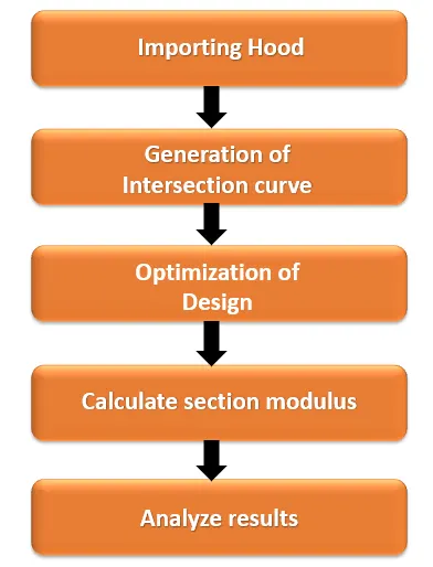
6. Steps followed in design Process:
- Importing of hood model to the workbench.
- Selecting the midplane of hood and generating the intersection curve.
- Measuring the section modulus of base model intersection curve.
- Modifying the sketch by offsetting the inner panel and measuring the section modulus.
- Modifying the sketch by reducing embosses the inner panel and measuring the section modulus.
- Modifying both reduced embosses and offsetting the inner panel and measuring the section modulus.
7. Baseline Hood model with Intersection curve:
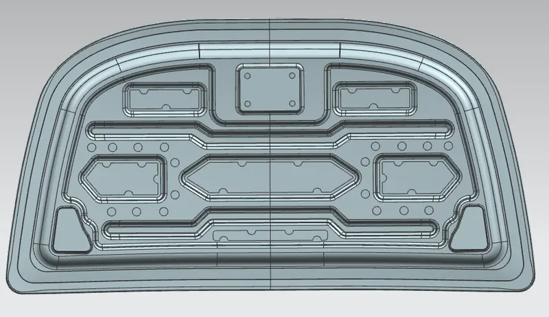
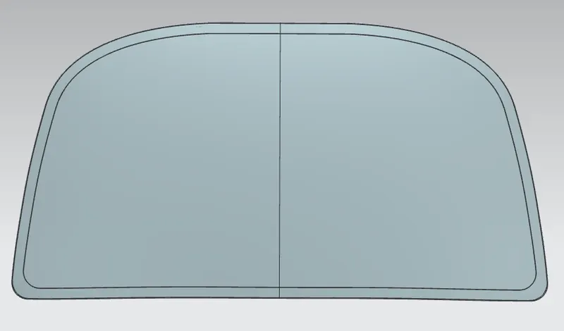
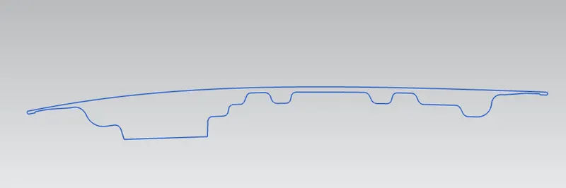 Intersection Curve
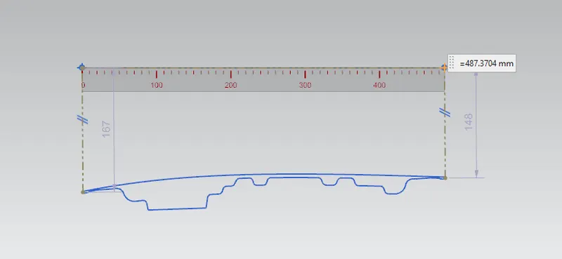 Neutral Axis Distance
8. Optimization of Design:
- Case 1: The section modulus of baseline hood model is measured without any changes.
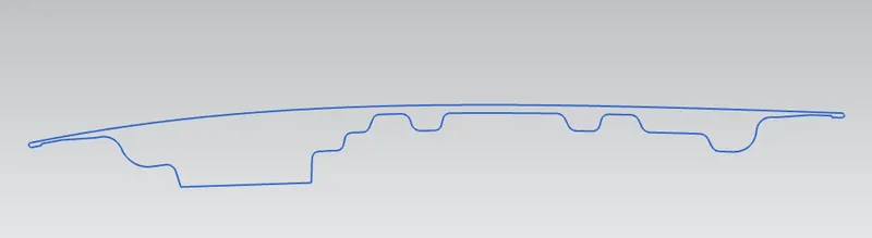
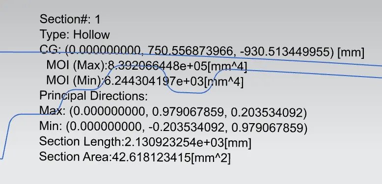
MOI (max) = 8.3920 ×10⁵ mm⁴ Y=487.2/2 = 243.6 mm
MOI (min) = 6.2443 ×10³ mm⁴
S=I/Y mm³
S = 6.2443 ×10³ / 243.6
S = 25.633 mm³
- Case 2: In this case, the minor embosses are reduced in hood inner panel as the design modification and section modulus is measured to analyse.
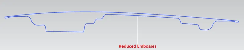
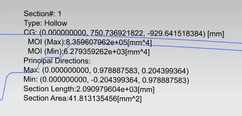
MOI (max) = 8.3596 ×10⁵ mm⁴ Y=487.2/2 = 243.6 mm
MOI (min) = 6.2793 ×10³ mm⁴
S=I/Y mm³
S = 6.2793 ×10³ / 243.6
S = 25.779 mm³
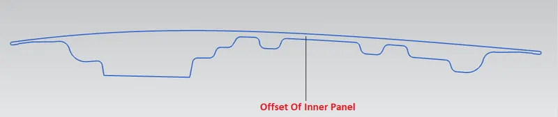
- Case 3: In this case, the hood inner panel is offsetted to 0.5 mm towards outward side in the baseline model, as the design modification and section modulus is measured to analyse.
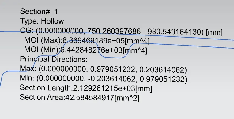
MOI (max) = 8.3596 ×10⁵ mm⁴ Y=487.2/2 = 243.6 mm
MOI (min) = 6.4428 ×10³ mm⁴
S=I/Y mm³
S = 6.4428 ×10³ / 243.6
S = 26.448 mm³
- Case 4: In this case, the minor embosses are reduced as well as the hood inner panel is offsetted to 0.5 mm towards outward side in the baseline model, as the design modification and section modulus is measured to analyse.
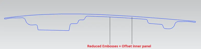
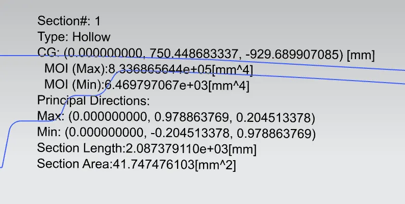
MOI (max) = 8.3596 ×10⁵ mm⁴ Y=487.2/2 = 243.6 mm
MOI (min) = 6.4679 ×10³ mm⁴
S=I/Y mm³
S = 6.4679 ×10³ / 243.6
S = 26.5578 mm³
9.Comparing of Results:
|
Cases |
MOI max in mm⁴ |
MOI min in mm⁴ |
Section Modulus |
|
Baseline model |
8.3920 ×10⁵ |
6.2443 ×10³ |
25.633 |
|
Reduced embosses |
8.3596 ×10⁵ |
6.2793 ×10³ |
25.779 |
|
Offset |
8.3694 ×10⁵ |
6.4428 ×10³ |
26.448 |
|
Offset Reduced embosses |
8.3368 ×10⁵ |
6.4697 ×10³ |
26.5578 |
- Conclusion:
Based on the requirement the section modulus of the hood is carried out and performed design optimisation on the hood to improve the mechanical properties externally. Different cases of design optimization of hood is performed in order to attain maximum effective hood design .the results shows that case 4,that is reduced embosses with offsetted design modification provides maximum effective section modulus for the hood. The NX CAD helps to make the design accomplishment easier within time constraint