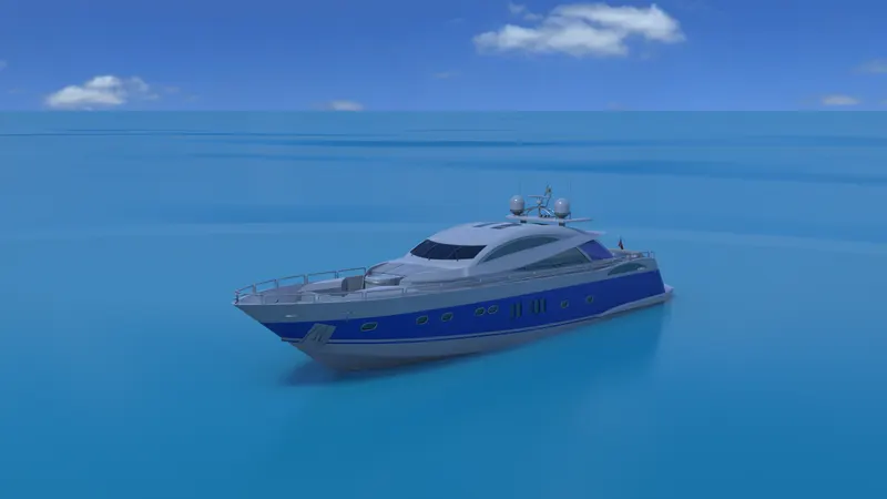
Radar Mast & Final Assembly of Yacht
- Title of the Project:
Modelling of Radar Mast
- Objective:
To Design and model the Radar Mast component of yatch using Solid works.
3. Description of Sketching and Modelling:
- Radar Mast:
Radar mast is a component which gets aligned on the surface of the super structure towards the extreme end. Initially the reference surface body of the super structure is imported. Using the blueprint, the bottom surface is sketched and extruded. Further an offset reference plane is created by selecting the midplane and dome, mast light was generated as per the geometry provided with exact dimensions and relations. Once the half section of radar mast is created using the mirror tool the body is selected and mirrored to form one single component by knitting surfaces and merging solids. Later by selecting the midplane the reference plane is offset and sirens were created and mirrored next to it and dome, shell, fillet radius were provided to the sirens. Finally appropriate appearances were provided for the radar mast assembly.
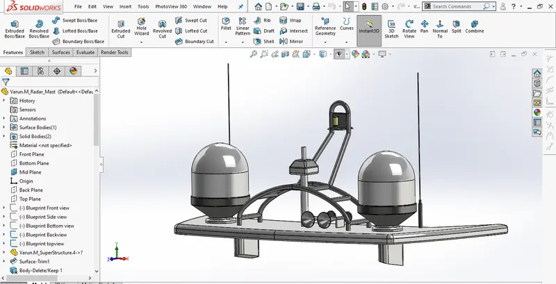 Feature tree of radar mast
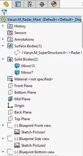
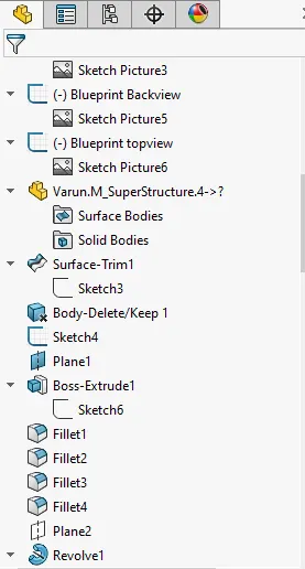
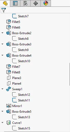
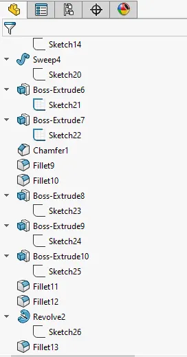
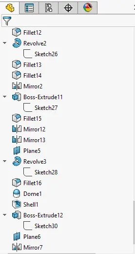 Full Fledged Feature tree of radar mast
- Modelled Components:
Radar Mast:
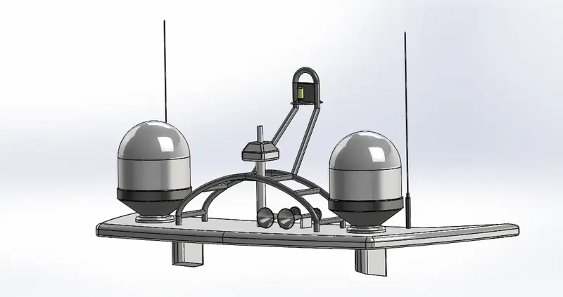 Radar mast isometric view
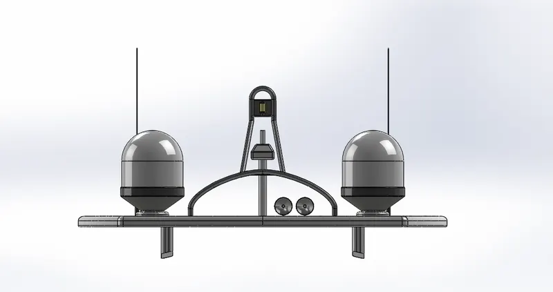 Radar mast front view
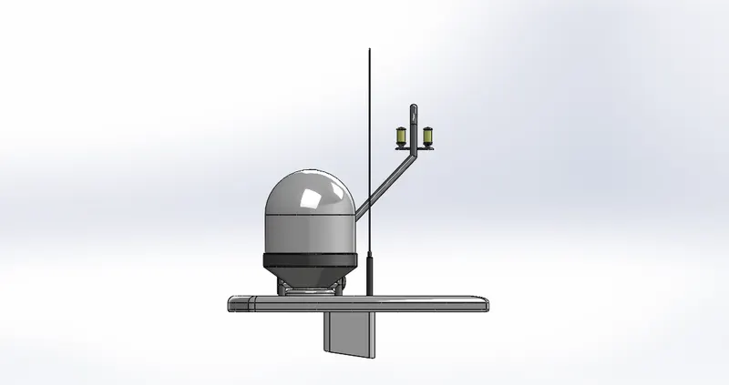 Radar mast side view
Conclusion:
The Radar mast component was modelled using Solid works with appropriate dimensions and relations followed by the geometry. The output design of the modelled components represents, the exact replica of an actual 3D model components of Yatch.
PROJECT REPORT ON YATCH ASSEMBLY
- Title of the Project:
“Design and Modelling of Yatch using Solid works”
- Objective:
To model and assemble the various components of Yatch and perform photorealistic rendering using solidworks.
- Introduction:
Solidworks is an effective and efficient modelling tool which are used globally. The user interface is very handy and helps to reduce the time consumption in modelling the complex designs and shapes. The design output provided by the solid works are more realistic and accurate. The components of the Yatch such as propeller, radar, superstructure, hull, seats, garage door, radar mast were modelled as per the dimensions. Further those components are assembled to generate complete model and also photorealistic rendering is performed using the solidworks CAD and Solidworks Visualize.
- Design methodology / approach:
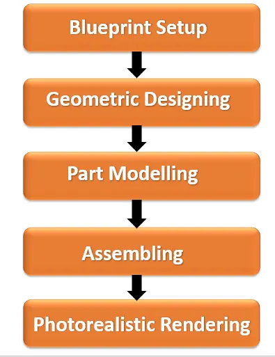
Methodology
- Description of Methodology:
- Blueprint Setup:
Blueprint is the first stage of designing process.in this stage by selecting different planes the blueprints of the model is been aligned exactly with respected planes. Initially front plane is selected and using sketch picture tool the blue prints of the front view is selected and aligned exactly, further by selecting right plane the blue print of side view of yatch is placed exactly. And by selecting top plane the bottom blue print of yatch is placed further a reference plane is created on the top of top plane.by selecting this reference plane the top blue print of yatch is aligned exactly. Later by creating another reference plane at backplane the rear blue print of yatch is placed exactly Once the blue print lay-off is created it can be further used to design the independent models of yatch easily and effectively. it plays a vital role during designing stage.
6. Geometric designing & Modelling:
- Propeller:
Propeller is a rotating component, which gets aligned on the hub. Initially right plane is selected and sketching of hub is crated, using sketch tools further appropriate dimensions and relations are given across the geometry. Further using revolved boss base option hub is generated.by selecting top plane rotor blades are sketched again by creating a reference plane on top plane. The geometry is sketched using lofted tool, later blade is extruded finally the fillet radius are provided at edges of blade.
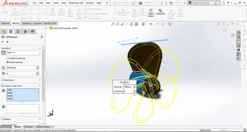
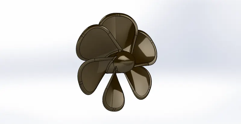 Modelling of Propeller
- Radar:
Radar is a rotating component and it is aligned on shaft.by selecting right plane the sketching is done further dimensions and relations are provided and extruded. Further by selecting one of the face the studs are created and a polygon cut-out is created on the top of studs. Further the fillet radius is given across the model.by using mirror tool the bodies are selected as a reference right plane is selected and mirrored. Finally, by selected front plane using sketch tools text is generated on the selected surface and appropriate appearance is provided using split option. The text is placed exactly on the surface
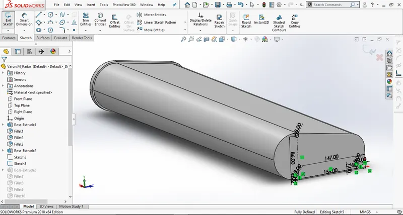
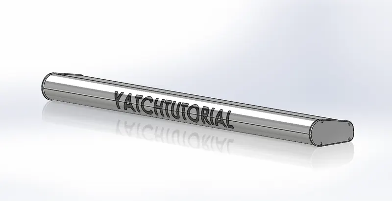 Modelling of Radar
- Hull:
Hull is a main base component of yatch, where all other parts get assembled on to it. initially the blueprint lay-off setup is imported, the outline of hull is sketched. Further using projected curve tool each and every edge the hull outline was generated. Later using this curve, the surfaces were generated using surfaced based tools. The edges were trimmed and fillet radius were given. Further Railings, Stairs, hub, shock absorber, anchor, windows, rope slit were generated using the blueprint provided with appropriate dimensions and relations. These parts required tools such as projection curve, split, extrude, extruded cut, mirror, reference plane, surface tools, dome, fillet sketch tools for their creation. Later garage space is generated by using split options and the body is saved for the garage door. Further fillet radius is provided across the hull edges, further appearance and decals were attached for the hull deck surface. Finally, a surface offset of deck surface is created for the reference for other components.
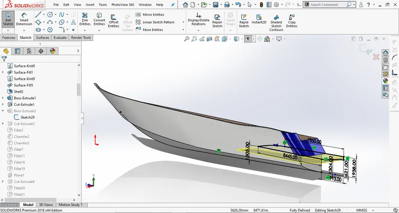
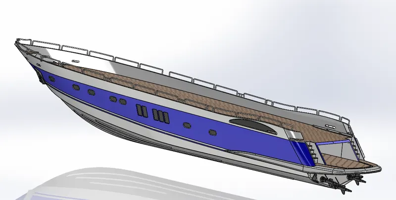 Modelling of Hull
- Garage door:
Initially the saved body of the garage space is imported, Uther an extruded cut is done based on the blue print dimension. Later extrude is created for pivoted points for the door. Later fillet radius is provided across the edges of the door. Using the mirror option, the body is mirrored for the other half. Finally, the appearance is provided with the text on the garage door using the split curve.
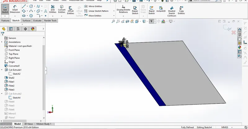
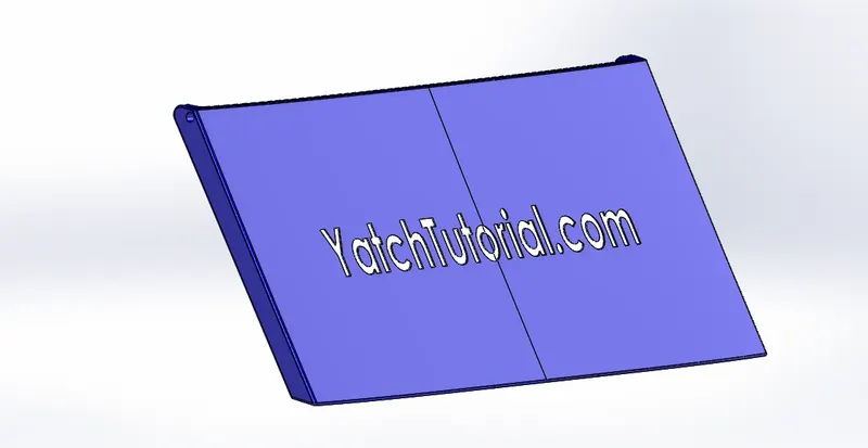 Modelling of Garage door
- Front, Middle, Rear seats:
Front, Middle, Rear seats is a component which gets aligned on the deck surface of the hull. Initially the reference deck surface of the hull is imported and using blueprint, the curve of the seat is created. Further these curves are transformed into surfaces. After surface creation the edges are trimmed and fillet radius were given as per the dimensions provided by the geometry. Once the surface boundaries of seat are patched, it is converted into solid body. Further surface offset is made and reference plane id created to make seats and fillet radius were provided. Later using mirror tool, the body is selected to create its other half of the seat. Finally appropriate appearances are provided for the Front, Middle, Rear seats.
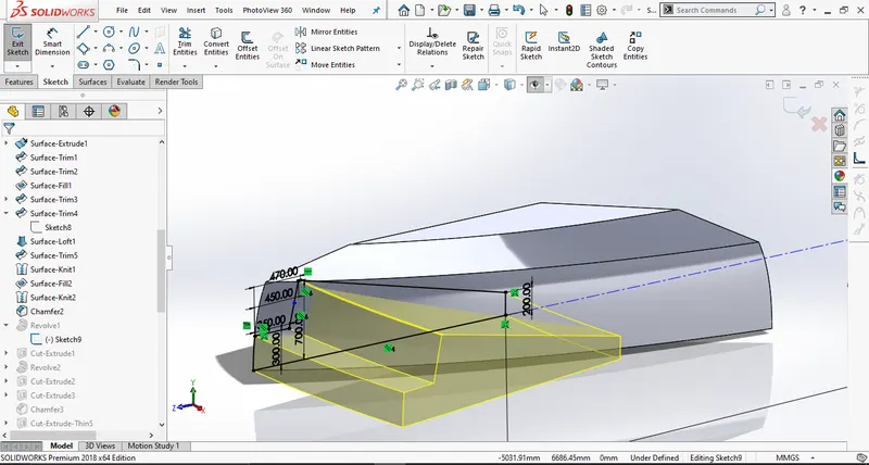
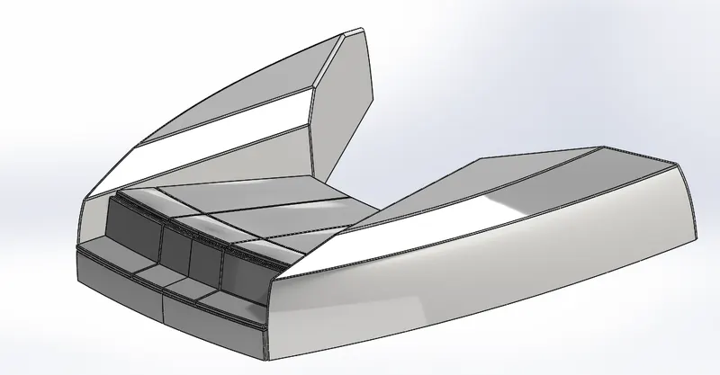 Modelling of Front seat
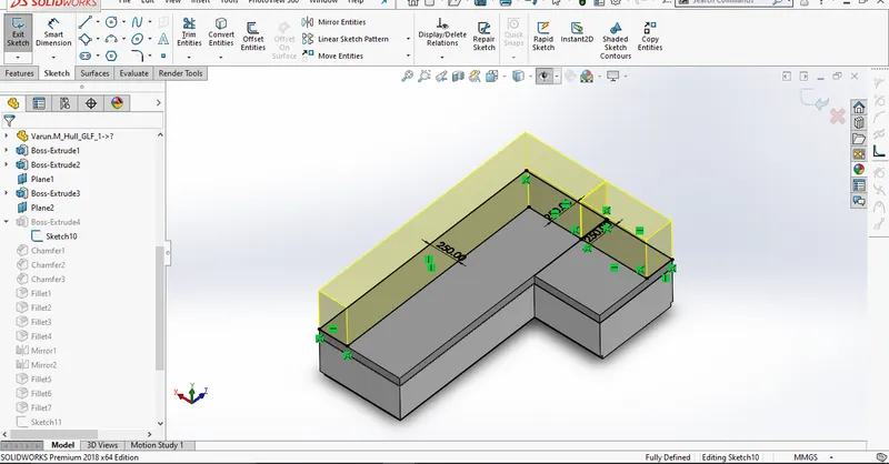
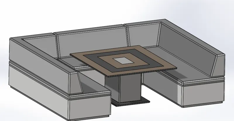 Modelling of Middle seat
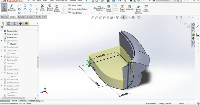
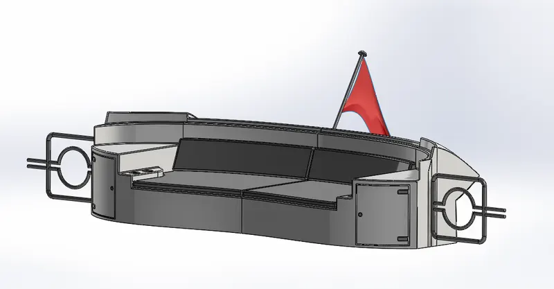 Modelling of Rear seat
- Super Structure:
Hull Super structure is a cabin component which gets aligned on the deck surface of the hull. Initially the deck surface body is imported and using the blueprint setup the outline is sketched and its dimensions and relations were provided. Further using projection curve tool, the surface of the structure is created, later the extra edge surface was trimmed and their boundaries ere patched using the filled surface. Later the window cut-outs were created on top and side surfaces of structure. Further wipers, railings, jacuzzi were generated using the projected curve tool and feature based tools. Once the overall surface is created, using the mirror option tool the other half of the super structure is created to form complete single model and it is been transformed into a single solid body. Further fillet radius was provided across the edges of super structure and appearance were provided for the super structure.
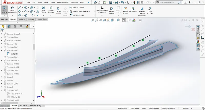
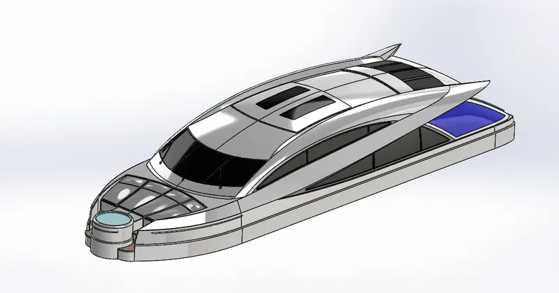 Modelling of Super structure
- Radar Mast:
Radar mast is a component which gets aligned on the surface of the super structure towards the extreme end. Initially the reference surface body of the super structure is imported. Using the blueprint, the bottom surface is sketched and extruded. Further an offset reference plane is created by selecting the midplane and dome, mast light was generated as per the geometry provided with exact dimensions and relations. Once the half section of radar mast is created using the mirror tool the body is selected and mirrored to form one single component by knitting surfaces and merging solids. Later by selecting the midplane the reference plane is offset and sirens were created and mirrored next to it and dome, shell, fillet radius were provided to the sirens. Finally appropriate appearances were provided for the radar mast assembly.
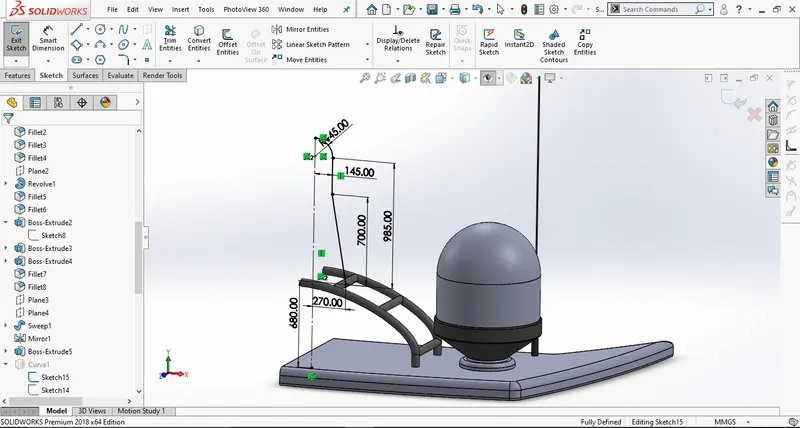
Modelling of Radar Mast
7. Assembly of Yatch:
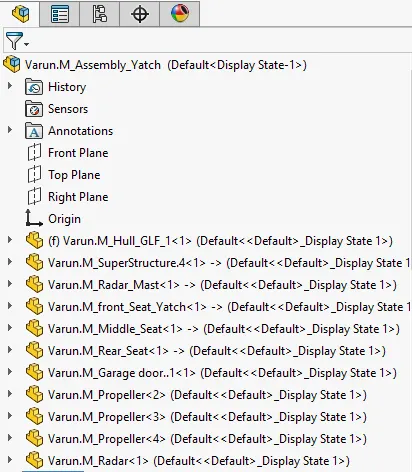
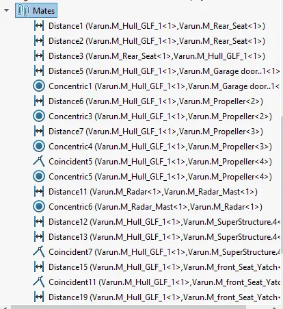
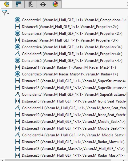
The Yatch consists of several parts such as, radar, propeller, hull, front, middle, rear seats, superstructure, radar mast and garage door. Initially the hull is imported to the assembly environment and it is made to fix to the bottom plane. Further the super structure is imported and distance mates are given between hull face and superstructure bottom face. And its front planes were made coincide. Further all three seats were imported to the assembly where all the bottom planes were selected and hull face is selected and provided with distance mates between them. And their front planes were made coincide with blueprint front plane. Further propeller is imported to the assembly environment and it is made coincide with the midplane of the hull and the end face of the hub and propeller inner face is selected and provided with concentric mates with their rotation locked. Further garage door is imported and its midplane is coincide with midplane of blue print. And also, the pivot point face and garage door slot face are made concentric in relation. Finally radar mast is imported and using distance mate the bottom of extrude face and superstructure top face is made to align perfectly.
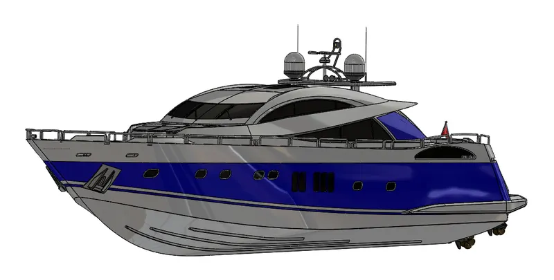 Isometric 1 view
 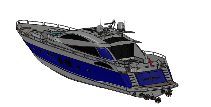 Camera 1 view
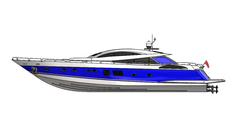 Side 1 view
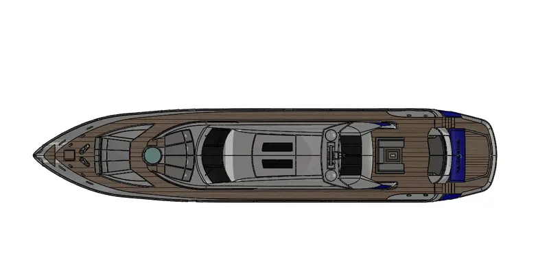 Top view
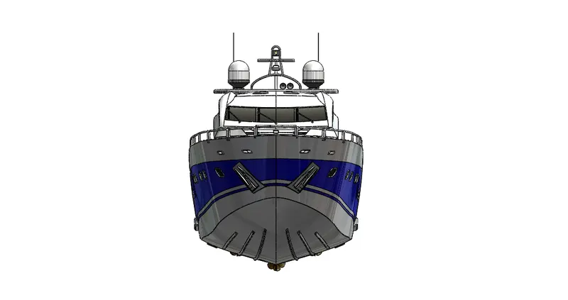
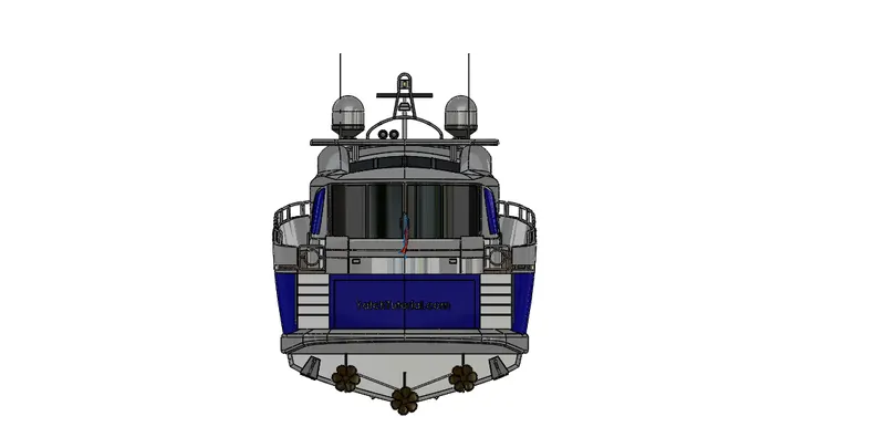
Front view Rear view
8 .Rendering:
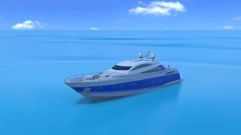
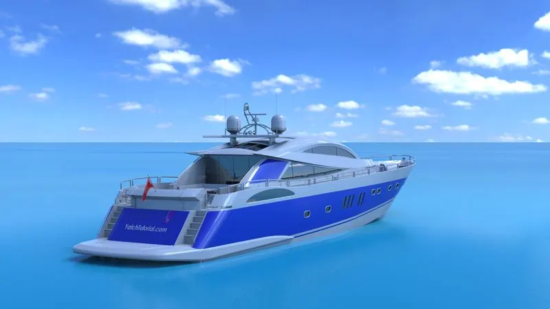
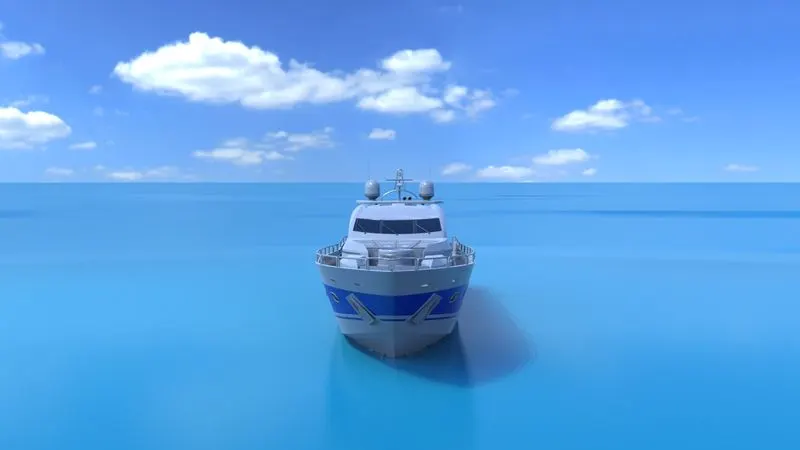
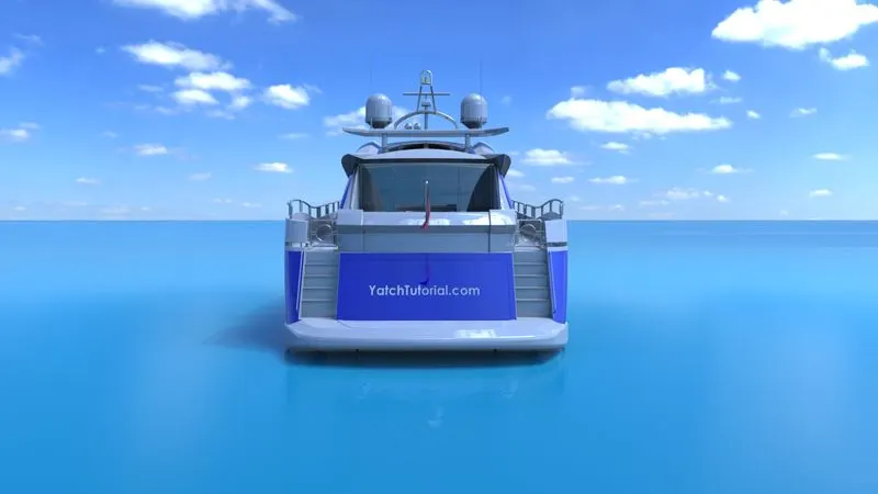
Rendering is a process of generating photorealistic images of modelled components. For the yatch the bottom plane is made offset to certain extent, so that the bottom surface yatch is touching the ground surface. Further decals, appearance, camera setup, is made across the yatch and finally scene, focal length brightness has been adjusted to get effective images. Finally, the models are been rendered.
Rendered Components of Yatch :
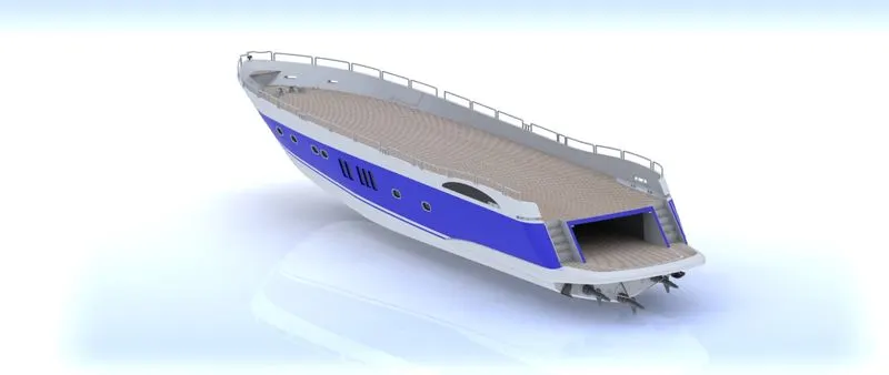
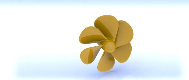
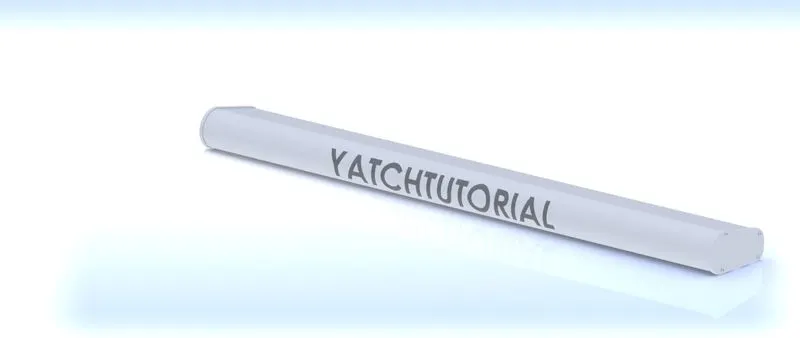
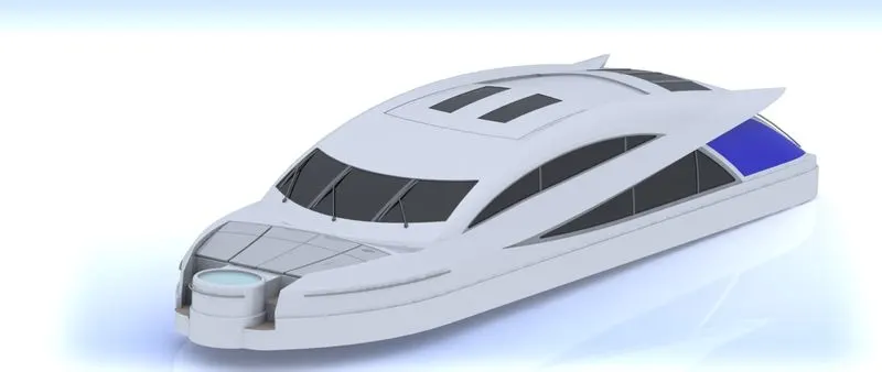
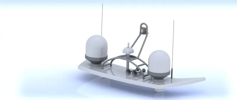
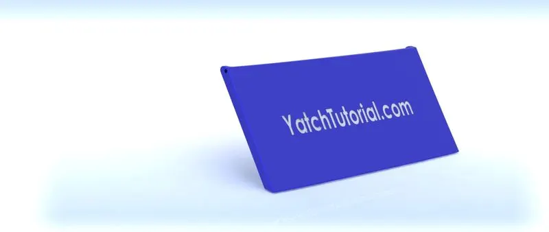
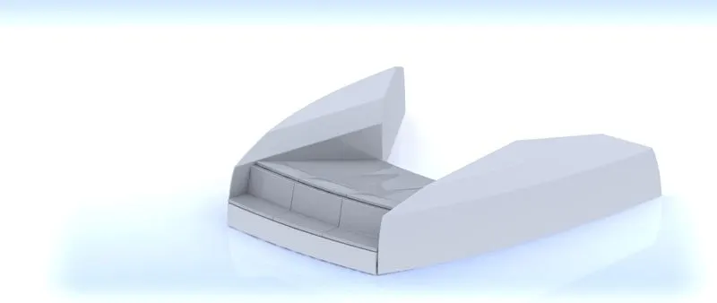
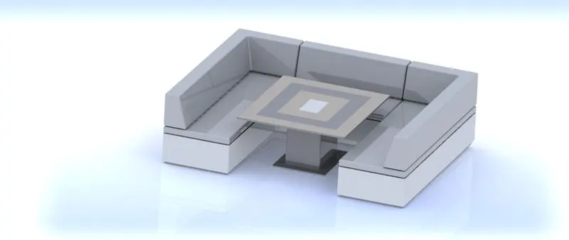
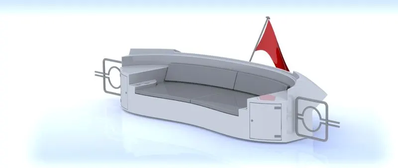
( Rendered model of Yatch using Photoview 360 ) :
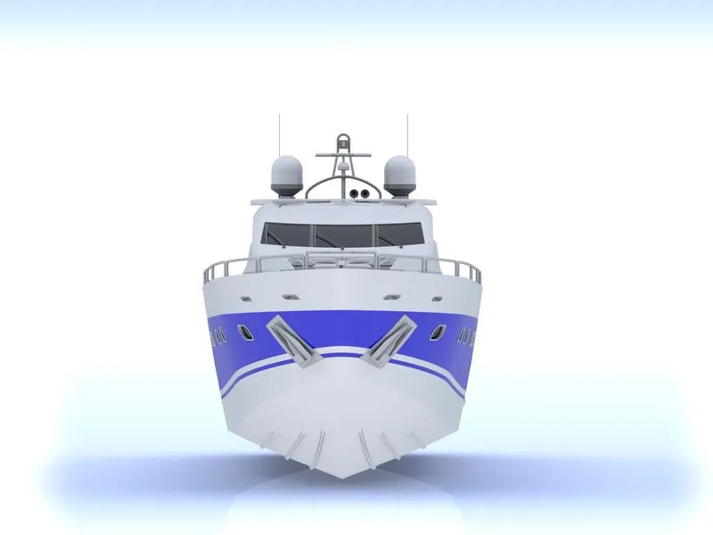
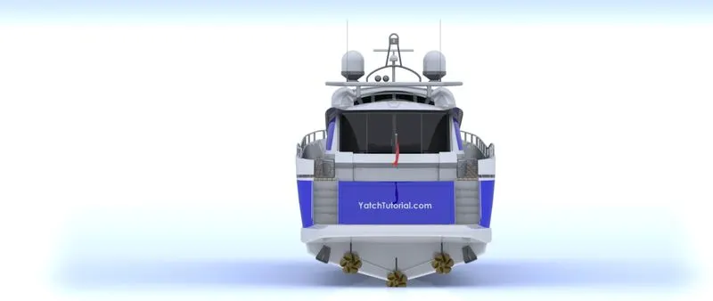
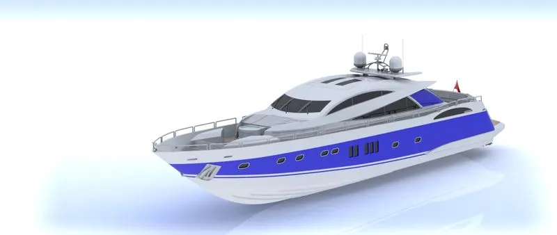
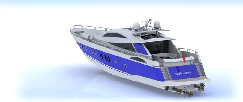
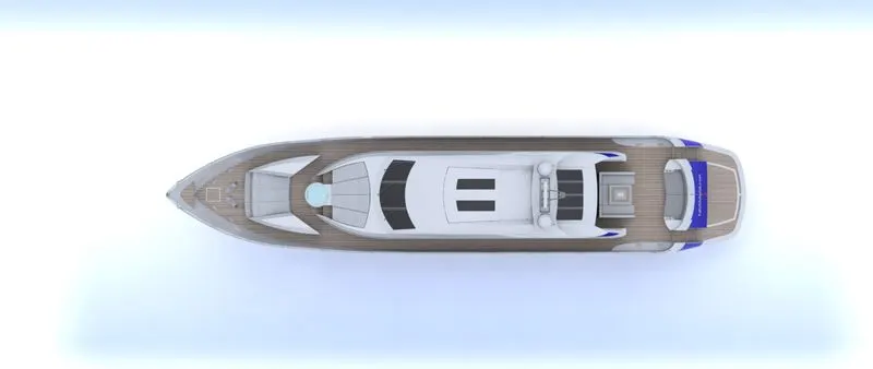
( Rendered model of Yatch using Solidworks Visualize ) :