Week 8 - Challenge 2 - Base Bracket Design
- Title of the Project:
Design and model the Base Bracket Plastic component through the given Class-A surface data, using Catia V5.
- Objective:
To create the base bracket plastic component through Class A surface,by creating tooling axis and perform draft analysis fot the component using catia V5.
- Methodology:
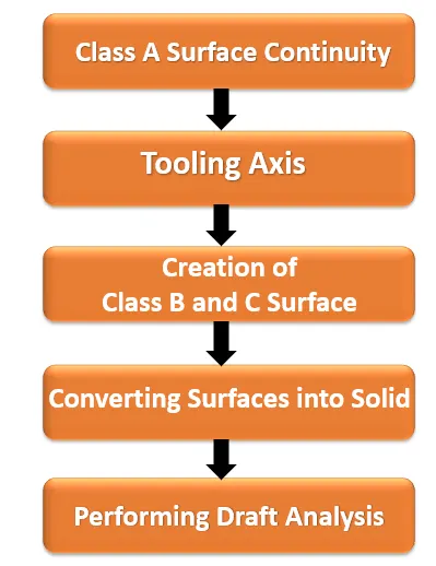
- Class A Surface continuity:
It is the initial stage, such that the class A surface input data is verified for its continuity, and ensures that there is no dis continuity in between two surfaces in the model.
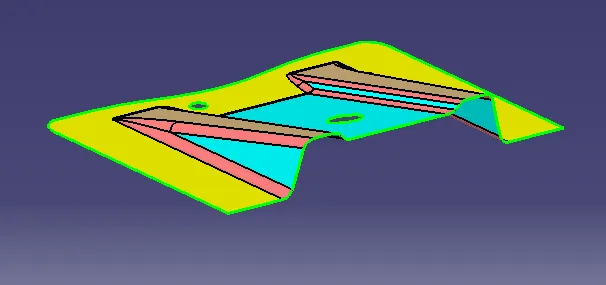
- Creation of tooling axis:
Initially analysing the model visually to check which direction would be most optimum for tooling axis, such that it would result in gaining better product with optimum cost, by selecting the X and Y axis planes an intersection is generated. Using the bisecting lines the intermediated tooling clearing along their direction is generated. Using this tool clearing direction lines, the actual tooling axis is created for the fan cover model.
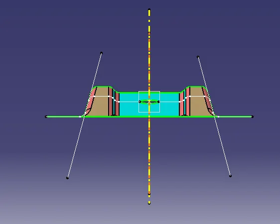
- Creation of Class B surface:
Class B surfaces are the surfaces which consists of engineering design for the class A component.it may consists of ribs, latches, fits, stiffener etc. initially the class A surfaces are extracted and individually and offsetted to certain distance and using surface features exact replica of class a surface is generated.
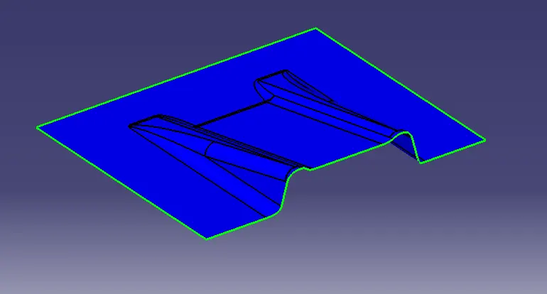
- Creation of Class C surface:
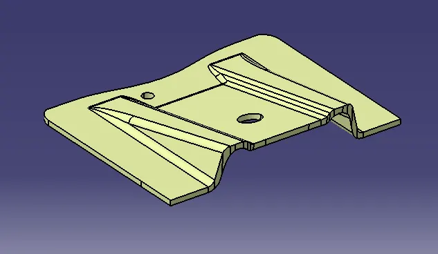
Class C Surfaces are the surfaces which connects class A and B surfaces together to form a single model. This surface is generated using sweep option by giving the desired draft angle for the model and it is blended with class A and class B to form a complete design of the component.
- Converting of Surfaces into solid:
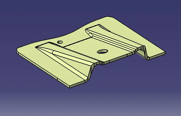
After designing the complete surface model by swapping into part workbench, using the close surface option, the surface model is converted into solid model.
- Performing draft analysis:
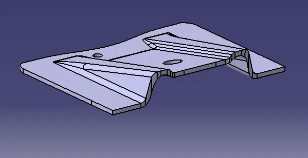
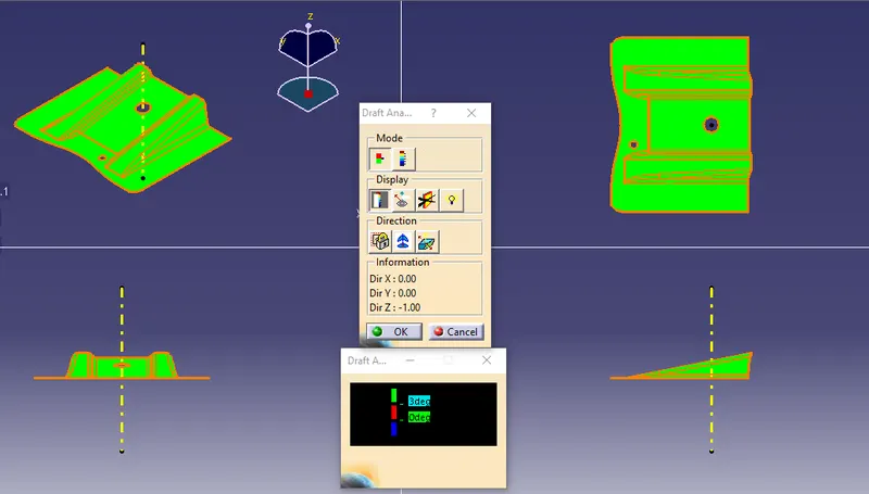
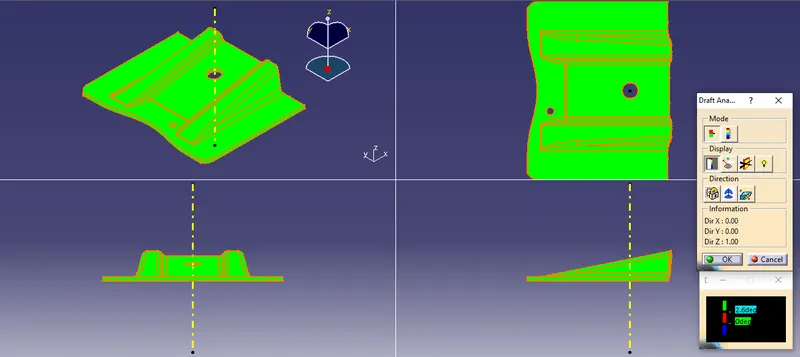
By applying the material to solid model, draft analysis is done by aligning the compass to the tooling axis and minimum and maximum draft angle is entered to get the desired result on the model. After interpreting, if there are any negative draft angle is identified, then the tooling axis or the model needs to be isolated for further design correction.
(Class A Surface, draft analysis Results):
(Solid Model,draft analysis Results):
Draft analysis:
Draft analysis is performed on a component in order to identify whether there is any negative and positive angle is involved in the component.This draft angle allows the part to eject easily from the mold. The draft angle reduces the friction between mold andpart.it also tends to avoid the damage occurring to the mold and part during ejection processes frequently used draft angle is 3 and minimum draft angle is 0.5.
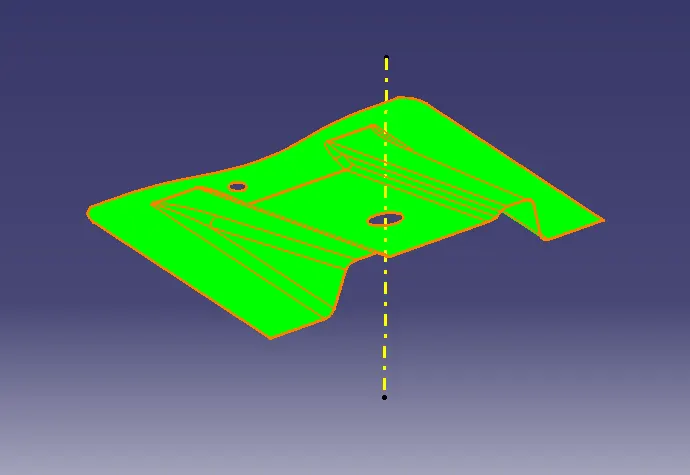
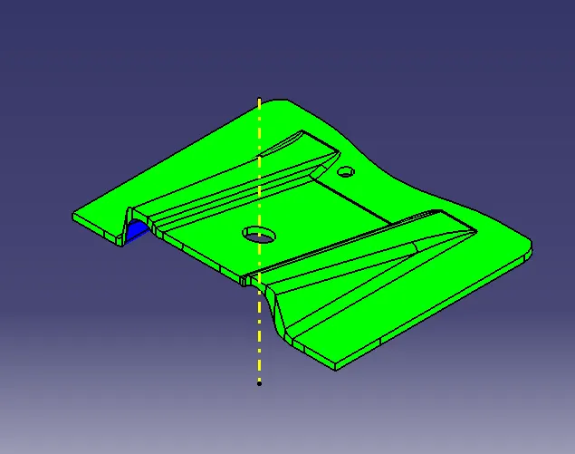
Draft analysis on surface Draft analysis on Solid body
Publication:
It is a feature used to make an easy access of the sketch or the surface feature. This feature reduces the time of searching for exact feature which is inside the geometrical set or the part body.
- Modelled Components:
Iso view of Surface model Iso view of Solid model
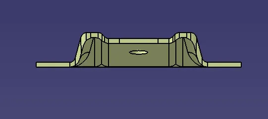
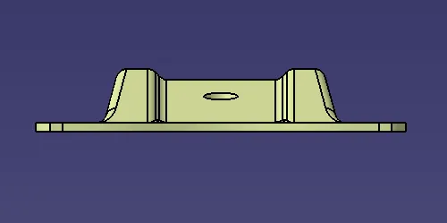
Front view Rear view
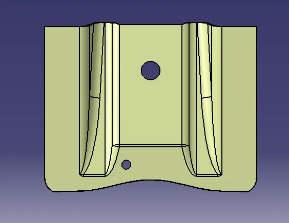
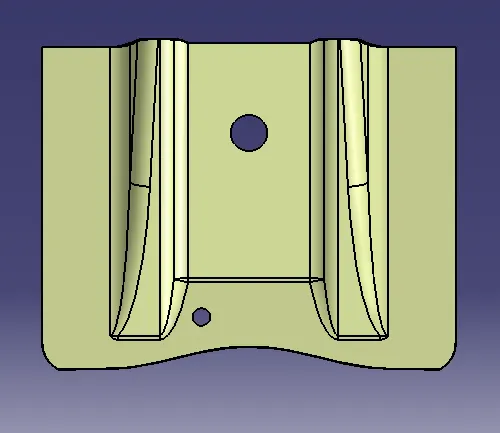
Top view Bottom view
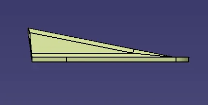
Side view
- Conclusion: