Roof challenge
- Title of the Project:
Design of Roof and its Reinforcement using External Skin Data and perform Curvature study, Draft analysis, Section Modulus Through NX CAD 12.
- Objective:
To design and model the Roof and its components such as front, Mid, rear roof rail and bow roofs using master section data and skin data. And also perform Curvature study, Draft analysis, Section Modulus at 0-Y direction for the model using NX CAD 12.
- Introduction:
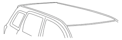
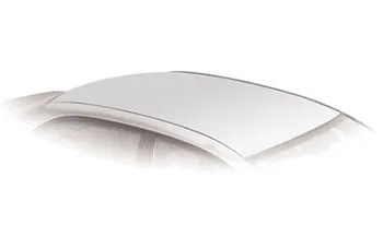
Roof top is one of the major Sheetmetal component in an automobile that its helps in providing safety for occupants inside the vehicle from external factors and elements. this roof top also plays a very important role in gaining safety standards. Whenever the vehicle is committed with collision or rollover state. These roofs should be able to take the load which is travelling inside the cabin compartment. Therefore, the roof top must be designed by considering various factors and also implement reinforcement flanges, perform analysis and test in order to attain an effective and strong roof top of a vehicle.Sheetmetal are widely used in generating the automotive body components, which is due to their lighter in mass, easy manufacturability, low cost of production and product within the time constraints and also helps in gaining design competencies of a component easily and accurately. Sheetmetal thickness may vary from 0.3mm to 12mm.they can be easily transformed into final model using simple pressing and bending operations. Sheetmetal components can be either a single part or tailored blanked part. roof is a component which plays a vital role in gaining safety standards and also in aesthetics appearances. Whenever while designing the roof, there are some major base data in order to satisfy. Therefore, a detailed report on how the roof top and its reinforcements is modelled and developed will be generated in this project by considering various factors followed in roof.
4.Methodology:
5.Description of Methodology:
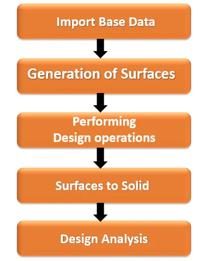
- Import Base data:
It is an initial stage of generating Roof. The skin profile body is imported to NX Workbench and its master section data is clearly analysed.
- Generation of Surfaces:
Based on the skin data, by offsetting the parent surface the actual working surfaces are created as per the design of master section.
- Performing Design operations:
After generating surfaces, the sketching is done on the various plane of Roof. Using this profile, the embossing operations are performed, cut-out is generated on the Roof. Further trimming, extending, mirror, thicken and sewing operations were carried out on the fender.
- Surface to Solid:
Once the surfaces of Roof and its components are completed as per the reference. the entire body surfaces are converted into solid body by providing the thickness value for the roof, as per the master section data.
- Design Analysis:
After converting surface of roof and its components, such as bow roof 1,2,3 and front, mid, rear roof rails into solid. The solid is selected for verified for draft analysis by taking its section along 0-Y axis. The section modulus of all the components were analysed. Further curvature study is performed, heat distortion and snow load calculation were carried out as a part of design analysis.
6.Steps followed in design Process:
- Importing of skin profile data (Roof).
- Offsetting of roof to create working surface as per the master section data.
- Sketching of profile on the roof by selecting various plane in order to create the embosses.
- Generating of front roof rail using the offset surface and law extension as per master section.
- Generating of bow roof rails by partitioning of the roof evenly.
- Generating of centre roof rail within the reinforcement using surface offset.
- Generating of rear roof rail based on master section data.
- Creating of sunroof cut out and embosses on roof and flanges.
- Performing draft analysis on the all-individual components.
- Analysing the section inertia at 0-Y direction of model.
- Analysing the roof and its components for heat distortion and snow load condition.
7. Roof and its Reinforcement flanges:
- Roof:
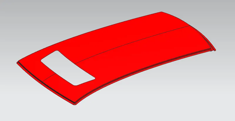
Roof top is one of the major Sheetmetal component in an automobile that its helps in providing safety for occupants inside the vehicle from external factors and elements. this roof top also plays a very important role in gaining safety standards. Whenever the vehicle is committed with collision or rollover state. These roofs should be able to take the load which is travelling inside the cabin compartment. Therefore, the roof top must be designed by considering various factors and also implement reinforcement flanges, perform analysis and test in order to attain an effective and strong roof top of a vehicle.
- Front Roof rail:
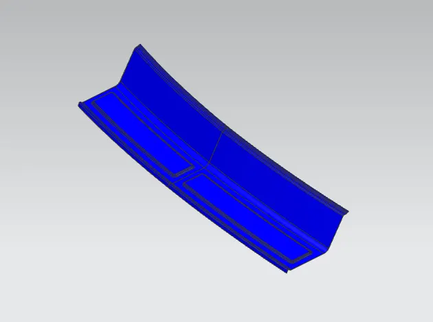
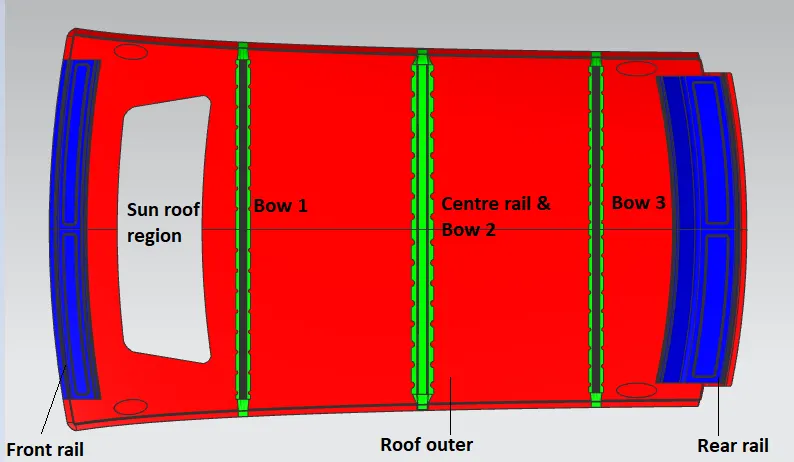
It is a supporting member which is aligned and joined in between body side outer and inner panels, along with front windshield. These front roofs are designed by considering various design and safety criteria such as visibility and headroom clearance. These front roof rails are normally joined using spot welding or using mastic sealants.
- Centre Roof rail with reinforcement:
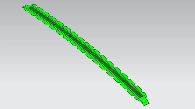
It is a supporting member which is aligned and joined in between body side outer and inner panels. Sometimes these roofs are spot welded with reinforcement flanges. Centre roofs are designed by considering various design and safety criteria such as visibility and headroom clearance. These roof rails are joined using spot welding or using mastic sealants.
- Rear Roof rail:
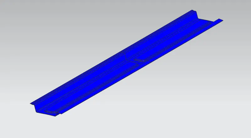
It is a supporting member which is aligned and joined in between body side outer and inner panels, along with back door. These front roofs are designed by considering various design and safety criteria such as visibility, headroom clearance and also back door opening clearance. These roof rails are joined using spot welding or using mastic sealants.
- Bow Roofs:
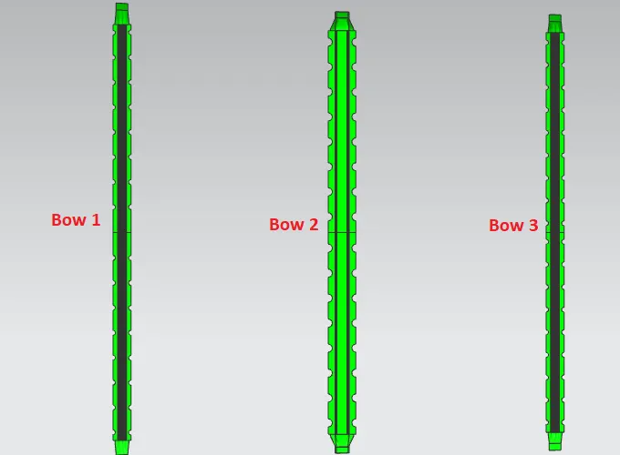
Bow roofs are reinforcement flanges which is aligned and joined in between body side outer and inner panels. These flanges help in providing additional stiffness to the roof top, in order to reduce the impact load entering the cabin compartment during collision. These bow roofs are joined using mastic sealants. The design of bow roofs is dependent on vehicle dimensions and global region requirement.
8. Design Analysis:
- Curvature study:
Curvature study of the roof is performed, in order to justify the positions of bow roofs. This curvature study involves criteria such as.
- Heat distortion criteria.
- Snow load criteria.
- Heat distortion criteria:
Heat distortion temperature is a temperature at which the metal tends to lose its properties by softening and results in deforming under the specific load. This test is performed in order to verify, the ability of the roof to withstand high temperature with respect to position of the bows and reinforcement that helps in gaining strength indirectly.
Steps involved:
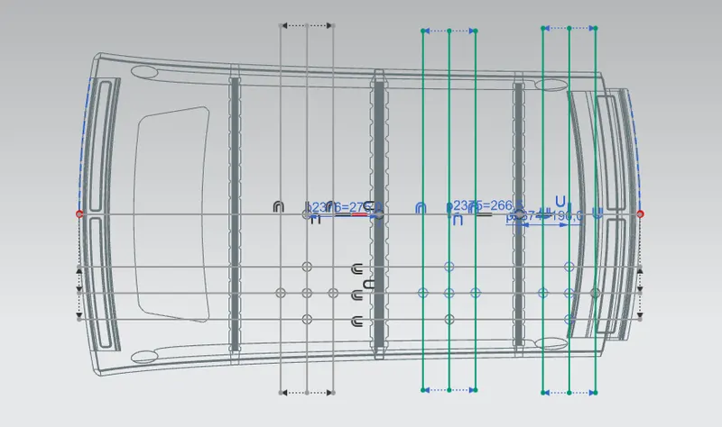
- Create a line at centre of the roof part at 0-Y axis, offset the centre line to 300mm towards -0-Y direction.
- Create an offset line of 100mm each on either side of the 300mm line.
- Create a line between two rails in Y direction and offset these lines with distance of 100mm each on either side line.
- Mark the intersection points and project those points on the roof top.
- Connect those points using arc along X-X and Y-Y direction,
- Measure the radius of two arc to get Rx and Ry values. Measure other required values on the roof and calculate heat distortion value for the roof using the standard formula.
Bow–roof prediction Formula :
W = [1.73 x 10^ (-3) x L] + [1.85 x 10^ (-8) x (R^2)/t] + [ 1.10x10^ (-3) x l] - 2.68
Judgement Condition: OK< 2.7> 3.1
Where,
L = Roof Length in X-Direction[mm] (Roof dimension in 0-Y)
R = Roof curvature
R = 2(Rx*Ry)/(Rx+Ry)
Rx = X curvature
Ry = Y curvature
t = Roof plate thickness [mm]
l = Bow Roof Span [mm]
when the corresponding values are substituted in formula,it exhibits the results.which are tabulated.
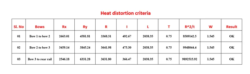
Since the model has sunroof,the heat distortion region between front rail and bow 1 is neglected.
- Snow load criteria:
Snow load criteria is a study, which tends to verify that the roof top will be able to withstand the snowfall and regains its original shape and structure without undergoing any permanent deformation, after the load is being removed from the roof top. The snow load criteria is a mandatory test for global countries in order to satisfy the safety standards.
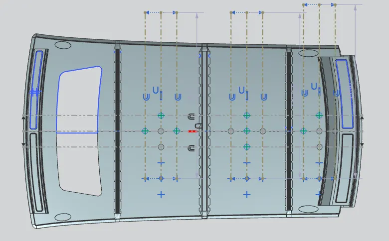
- Create a line at centre of the roof part at 0-Y axis.
- Create an offset line of 100mm each on either side of the centre line.
- Create a line between two rails in Y direction and offset these lines with distance of 100mm each on either side of the mid line.
- Mark the intersection points and project those points on the roof top.
- Connect those points using arc along X-X and Y-Y direction,
- Measure the radius of two arc to get Rx and Ry values. Measure other required values on the roof and calculate snow load value for the roof using the standard formula.
- Snow load Prediction formula.
Snow load Formula :
Qr = [Iy x t2] / [α x s x [(Rx + Ry)/2]2 x 10-8]
Where,
α = My x Lx2 x 10-12 , My = Y(Ly-Y)
Judgement condition = Qr ≥ 3.1
250 ≤ s ≤ 380
t = Roof plate thickness [mm]
Ly = Distance between the front and rear roof Rails on the Vehicle along with 0Y[mm]
Length of Roof panel with the centre point between Roof rail Front /Rear as the front and rear reference point.
Lx = Distance between the Left and Right end of the roof on the Roof BOW [mm]
Width of the roof panel exposed on the surface.
Y = Distance front Roof Rail to Roof BOW [mm]
s = Distance for which Roof BOW bears divided load [mm]
s = L1/2 + L2/2
Iy = Geometrical moment of inertia of Roof BOW (Y cross-section) [mm4]
Rx = Lateral direction curvature radius of roof panel Y cross-section on Roof BOW [mm]
Roof panel curvature Radius of the Length Lx in Front view
Ry = Longitudinal Direction curvature radius of the Roof panel X cross-section on Roof BOW [mm]
Roof panel X curvature radius of length s in Side view.
when the corresponding values are substituted in formula,it exhibits the results.which are tabulated.
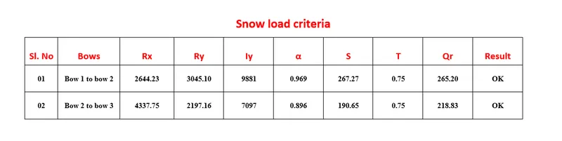
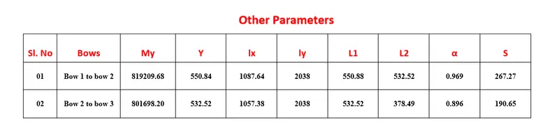
Since the model has sunroof,the snow load region between front rail and bow 1 is neglected.and also after rear rail there is no surface which is L2,therefore snow load from bow 3 to rear rail is neglected.
9.Section Modulus:
Section modulus is a geometric property of a given cross-section, that are used in design of beam or flexural members.it can also be defined as direct measure of strength of any sectional area of a component by its neutral axis.it is also known as torsional section modulus or polar modulus. Other geometrical properties that are used in design area for tension and shear, radius of gyration for compression, moment of inertia and polar moment of inertia for stiffness. This relationship between geometric properties is dependent on shape of the component.
Bow 1:
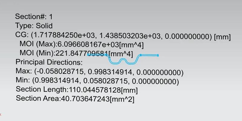
MOI (max) = 6.0966 ×10³ mm⁴ Y=44.90/2 = 22.45 mm
MOI (min) = 221.847 mm⁴
S=I/Y mm³
S = 221.87/22.45
S = 9881 mm
Bow 2:
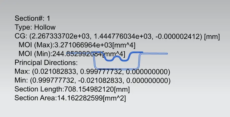
MOI (max) = 3.2710 ×10³ mm⁴ Y=69/2 = 34.5 mm
MOI (min) = 244.85 mm⁴
S=I/Y mm³
S = 244.85/34.5
S = 7097.1 mm
Bow 3:
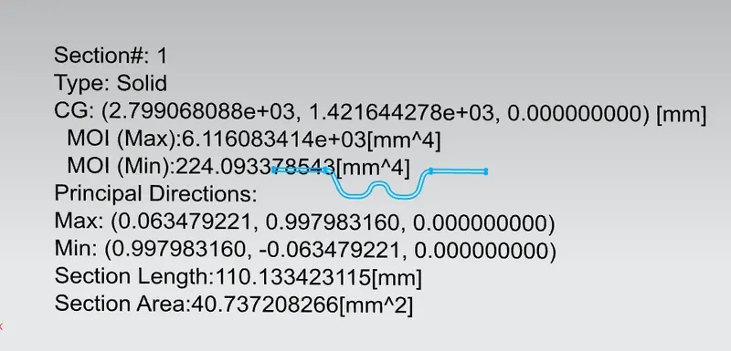
MOI (max) = 6.1160 ×10³ mm⁴ Y=45/2 = 22.5mm
MOI (min) = 224.097 mm⁴
S=I/Y mm³
S = 224.09/22.5
S = 9959 mm
10.Draft Analysis:
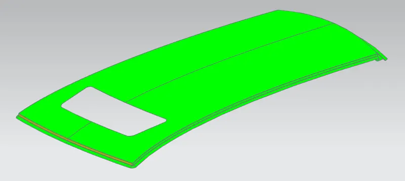
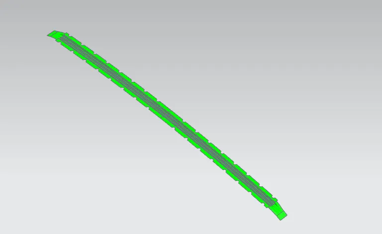
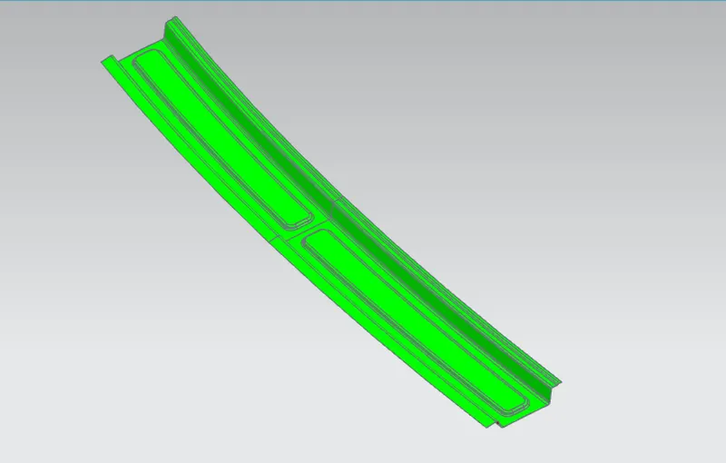
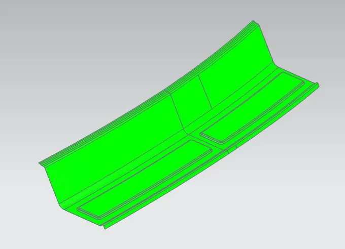
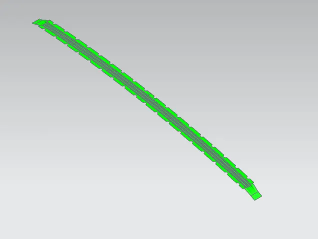
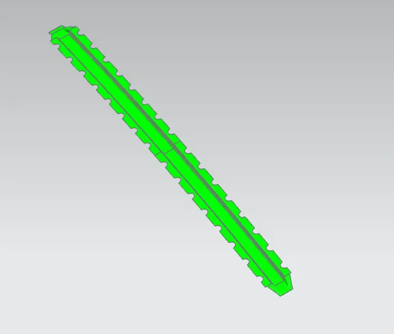
Draft analysis is a test which is done to components in order to analyse the draft angle. This draft analysis helps to check whether the product will be easily removed from the tool. The minimum draft angle provided for the roof was 5º. draft is nothing but change in angle.
Roof, Front rail, Rear rail, Center rail, Bow 1,2,3........
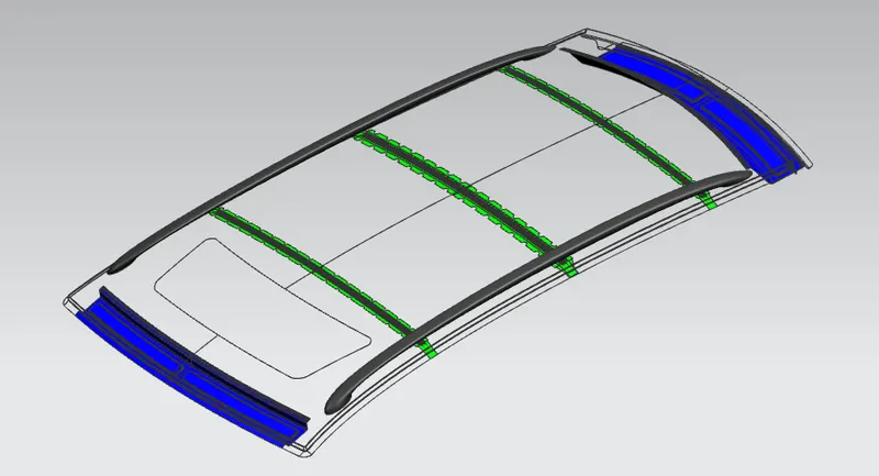
11.Modelled Components:
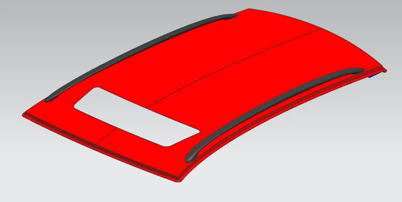 Isometric view
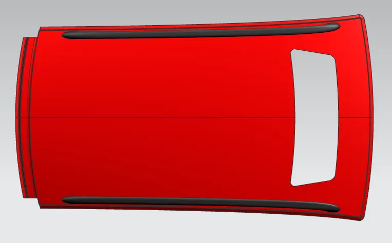 Top view
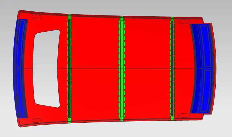 Bottom view
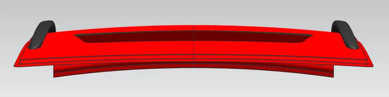 Front view
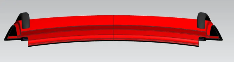 Rear view
12.Conclusion:
The design and modelling of Roof and its reinforcement components such as front, Mid, rear roof rails and bow roofs has been generated successfully, as per the dimensions provided in master section data using the skin profile model through NX CAD. And also performed Curvature study, Draft analysis, Section Modulus at 0-Y direction for the model using NX CAD 12. The final roof model component tends to appear as the exact replica of the given reference model. The NX CAD helps to make the design accomplishment easier within time constraint.