Design of backdoor
- Title of the Project:
Design of Backdoor Assembly and its Reinforcements using External Skin Data, Through NX CAD 12.
2. Objective:
To design and model the Back door assembly and its reinforcement components such as Hinge, gas stay, wiper motor, latch reinforcement using NX CAD 12.
3. Introduction:
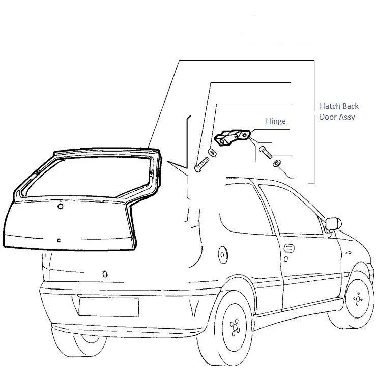
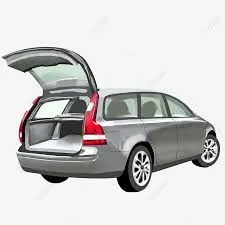
Back door is one of the major Sheetmetal component in an automobile that its helps in providing safety for occupants inside the vehicle from external factors and elements. Back door also plays a very important role in gaining safety standards. Whenever the vehicle is committed with collision from its rear end side. These tail gate should be able to take the load which is travelling inside the cabin compartment. Therefore, the back door must be designed by considering various factors and also implement reinforcement flanges, perform analysis and test in order to attain an effective and tail gate of a vehicle. Sheetmetal are widely used in generating the automotive body components, which is due to their lighter in mass, easy manufacturability, low cost of production and product within the time constraints and also helps in gaining design competencies of a component easily and accurately. Sheetmetal thickness may vary from 0.3mm to 12mm.they can be easily transformed into final model using simple pressing and bending operations. Sheetmetal components can be either a single part or tailored blanked part. Back door is a component which plays a vital role in gaining safety standards and also in aesthetics appearances. Whenever while designing the tail gate, there are some major base data in order to satisfy. Therefore, a detailed report on how the back door and its reinforcements is modelled and developed will be generated in this project by considering various factors followed in back door.
4.Methodology:
5.Description of Methodology:
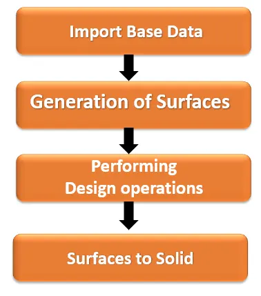
- Import Base data:
It is an initial stage of generating back door. The skin profile body is imported to NX Workbench and surfaces data is clearly analysed.
- Generation of Surfaces:
Based on the skin data, by offsetting the parent surfaces the actual working surfaces are created as per the design of requirement.
- Performing Design operations:
After generating surfaces, the sketching is done on the various plane of tail gate. Using this profile, the embossing operations are performed, cut-out is generated on the panels. Further trimming, extending, mirror, thicken and sewing operations were carried out on the various panels of back door.
- Surface to Solid:
Once the surfaces of back door and its reinforcements are completed as per the reference. the entire body surfaces are converted into solid body by providing the thickness value for the tail gate, as per the freeze design requirement.
6.Steps followed in design Process:
- Importing of skin profile data (Backdoor).
- Offsetting of back door surfaces to create working surface based on design requirement.
- Creating of Inner panel, by offsetting skin profile.
- Sketching of profile on the panels by selecting various plane in order to create the embosses and cut outs.
- Creating of Hinge mountings and its reinforcements.
- Creating of Gast stay mountings and its reinforcements.
- Creating of latch mounting and its reinforcements.
- Creating of wiper motor mounting and its reinforcements.
- Generating of outer panels of back door.
- Performing Hemming operation between outer panel and inner panel.
- Mirroring and sewing of components.
- Converting all surface model into solid model parts.
- Back door outer panel:
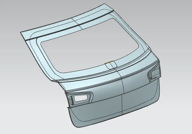
Outer panel is just a styling surface which is 0.75mm thickness. This outer panel helps cover the entire back door without compromising the external aesthetic appearances.
- Back door inner panel:
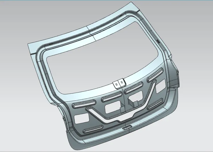
Inner panel is a component that, acts as reinforcement material for the outer panel, such that it has thickness of 0.75 mm.the inner panel is provided with several embosses and cut outs on it, in order to increase the strength of the back door. The embosses are generated in the shape of Y or V with draft angle towards outside of the panel. This is because during the collision the impact is directed towards outside edge of inner panel.
- Hinge reinforcements (LH & RH) :
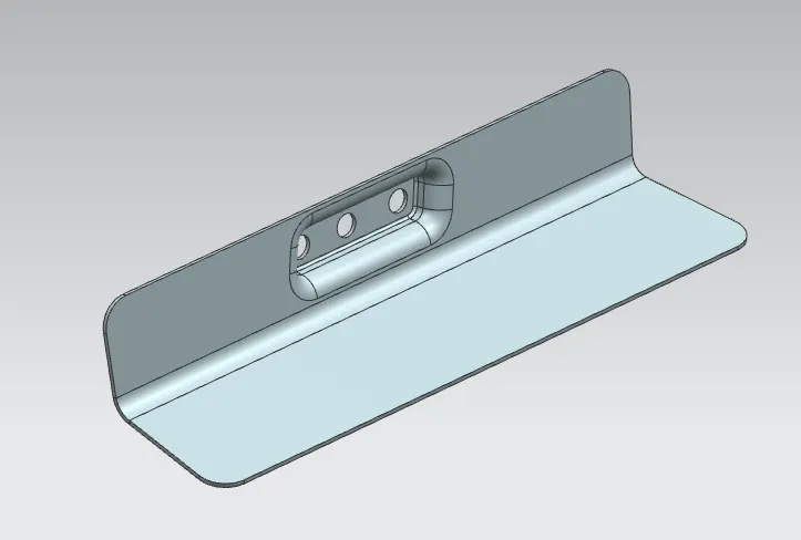
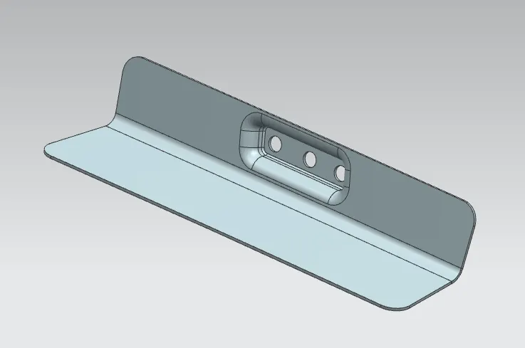
Hinge mounting embosses are created near top edge of the inner panel, such that the hinges for the door is mounted on this region. Since this region has embosses and bolting holes, the strength of the Sheetmetal at that region is not sufficient enough. Therefore, in order to compensate that strength, an additional structural reinforcement component is created and aligned between them, which is called hinge reinforcement.
- Gas stay reinforcement:
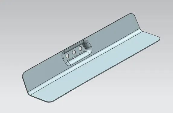
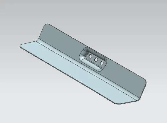
Gas stay mounting embosses are created near side edge of the inner panel, such that the gas stay brackets for the door is mounted on this region. Since this region has embosses and bolting holes, the strength of the Sheetmetal at that region is not sufficient enough. Therefore, in order to compensate that strength, an additional structural reinforcement component is created and aligned between them, which is called gas stay reinforcement.
- Wiper motor reinforcement:
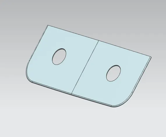
Wiper motor mounting embosses are created at mid region of the inner panel, such that the wiper motor for the door is mounted on this region. Since this region has embosses and bolting holes, the strength of the Sheetmetal at that region is not sufficient enough. Therefore, in order to compensate that strength, an additional structural reinforcement component is created and aligned between them, which is called gas stay reinforcement.
- Latch reinforcement:
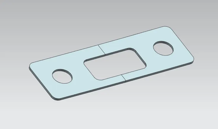
Latch mounting embosses are created near the bottom side edge region of the inner panel, such that the latch for the door is mounted on this region. Since this region has embosses and bolting holes, the strength of the Sheetmetal at that region is not sufficient enough. Therefore, in order to compensate that strength, an additional structural reinforcement component is created and aligned between them, which is called gas stay reinforcement.
- Trajectory Path:
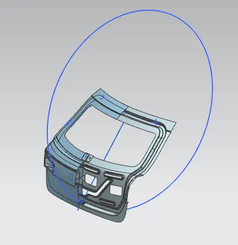
Trajectory path is a path, at which the door tends to travel in that direction for smooth operation without creating any tolerances problems. The latch and striker position of the back door is fixed based on this trajected path. The striker of the back door must be placed on the angular line to get better function ability. Initially an axis line is drawn horizontally by selecting the midpoint of hinge mounting embosses, from hinge axis midpoint an angular line is drawn vertically up to bottom edge of the back door. Further a circle is drawn from hinge axis midpoint that connects the vertical line up to bottom edge. If the latch and Stricker are not positioned on this trajected path then the door operation will result in geometric intolerance.
- Assembly of Back door and its Components:
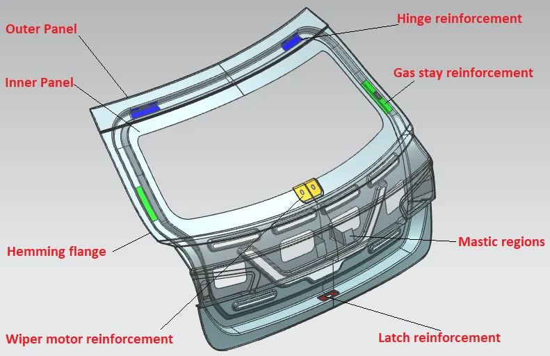
The design of back door must be able to satisfy the factors which are dependant on it such as, trunk space, taillamps, wiper motor, latch and sticker component. The back door is a combination of outer panel and inner panel in which both has the thickness of 0.75 mm.the back door is provided with several embosses and cut outs on it, in order to increase the strength of the back door. The embosses are generated in the shape of Y or V with draft angle towards outside of the panel. This is because during the collision the impact forces is directed towards outside edge of inner panel causing lesser damage to occupants. these panels are joined through hemming process along with mastic sealant.
11.Modelled Components:
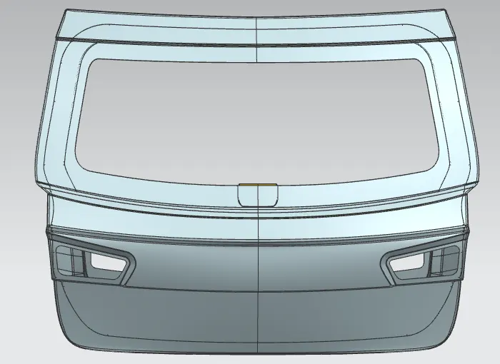 Front View
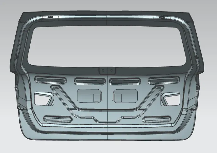 Rear View
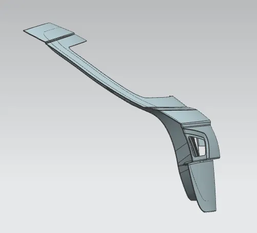 Side View
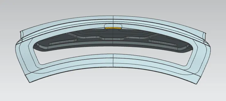 Top View
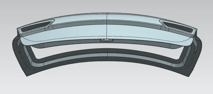 Bottom view
Isometric View
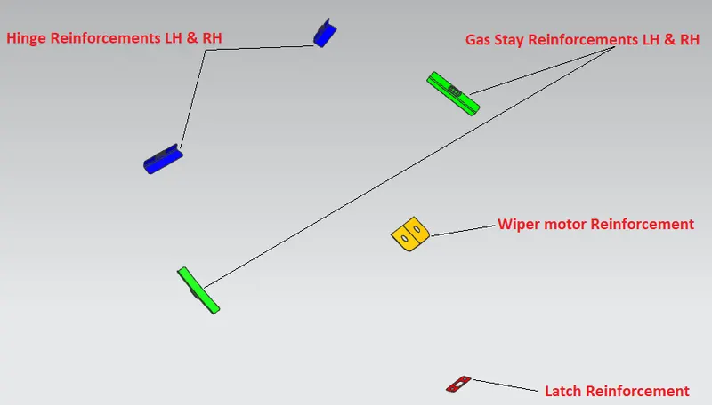 Reinforcements
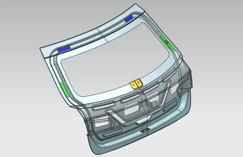 Assembly of Back door with reinforcements
12.Conclusion:
The design and modelling of Back door and its reinforcement components such as hinge, gas stay, wiper motor, latch mountings have been generated successfully, based on the design requirement of the skin profile model through NX CAD. The final Back door model component tends to appear as the exact replica of the given reference model. The NX CAD helps to make the design accomplishment easier within time constraint.