Advanced Sheet Metal Design Using NX Cad Challenge_5_Odd Shaped Enclosure
- Title of the Project:
Design of Odd Shaped Enclosure (Sheetmetal) using NX CAD 12.
- Objective:
To design and model the odd shaped enclosure (sheet metal) as per dimensions and generate drafting using NX CAD 12.
- Introduction:
Sheetmetal are widely used in all sectors of industries, which is due to their lighter in mass, easy manufacturability, low cost of production and product within the time constraints. Sheetmetal thickness may vary from 0.3mm to 12mm.they can be easily transformed into final model using simple pressing and bending operations CAD is a software package developed by siemens PLM software, which is widely used for designing and developing of sheet metal components.it also has various workbenches such as modelling, Analysis, drafting, Sheetmetal etc. CAD sheet metal workbench makes the design process of any sheet metal components easier.it helps in gaining design competencies of a component easily and accurately. The complex shapes of various designs can be made simpler using this software. Once the model is generated, it can also be flattened using design tools in order to get exact idea about how the actual blank may appear finally. Using this software, designers can easily judge whether the product developed is ready for manufacturability or not.
4. Design Methodology:
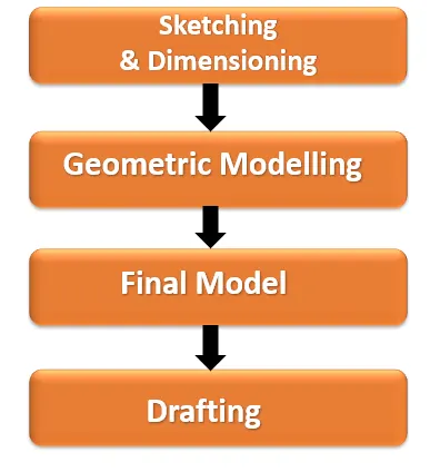
5. Description of Sketching and Modelling:
Sketching & Dimensioning:
It is an initial stage of any designing or modelling process, the outline of the geometry is created using sketch-based tools by selecting any one of the plane. Further appropriate dimensions and relations are provided for the sketch across its geometry using rapid dimensions.
Geometric Modelling:
Once the sketching and dimensioning are generated, those sketches and curves are selected for creating surfaces and solid components. features like Extrude, tab, flange, cut out, dimple were used to generate the operations on the component based on the design requirement.
Final Model:
After creating the model, the geometrical and design constraints are crosschecked across the component. If there is any changes and remodelling is needed the necessary actions were carried out as per the design requirement. Whenever the final model is satisfied using the flat pattern option, the component made to flatten to get better idea about the design.
Drafting:
Once the final model is generated and flattened, the design is dragged to the drafting workbench, where the appropriate sheet size is selected. Using base view, the various the various orientation of component is placed on the sheet with detailed information of the sheet metal component.
6. Steps Followed in design Process:
- Creating of geometry outline as per the dimensions and relations provided across the sketch.
- Creating of an extrude surface in order to generate solid body of odd shaped.
- Wrapping of a Sheetmetal on the exterior surface of solid body by selecting its corresponding faces.
- Adding of flanges on extreme left edge of generated Sheetmetal surface as per the design requirement.
- Creating of joggle operation on right end side of body by sketching a profile on its parallel plane.
- Unbending the surfaces to perform further operations, by selecting the mid face as its stationery face.
- Creating beads on the top surface by aligning them as per the design requirement.
- Creating of hole operations on the surface by creating a sketch profile on either side and at the top surface.
- Rebending of the sheet metal by selecting the bend surfaces to regain their actual shape as of the design geometry provided.
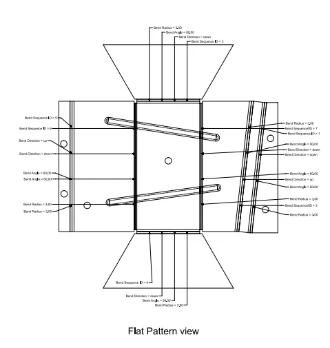
- Generating flat pattern of the odd shaped model by selecting the stationery face with lateral axis orientation.
- Drafting is done based on the various orientational views as required.
7. Tools and Features used:
Sketch tools:
Sketch tools are the basic commands which are normally used to create any geometry.
Ex: line, circle, arc, rectangle etc.
Extrude:
Extrude is a solid based feature command, which is used to create a solid body having a certain thickness. The extrude command requires a closed profile, depth value, direction of travel to execute successfully.
Flange:
Flange is a command, which is used to get a bend surface with respect to any surface or edge which is correspondent to it.the flange depends on various inputs such as length, relief, width, angle, type of flange, bend radius etc.
Joggle:
Joggle is a command which helps to lift the sheet metal from its base surface. This feature helps in generating flanges easily which has non even shapes. This command requires sketch profile, bend radius, length and direction.
Unbend:
Unbend is a command, which is used to remove the bend of a component temporarily by flattening the surface. This command tends to unbend sheet metal surface by keeping any one of the adjacent surfaces as its stationery surface.
Bead:
Bead is a command, which tends to lift the metal surface from its base.it requires the sketch profile, rounding radius, depth and direction to lift the surfaces respectively. Beads are created across the any sheet metal surface in order to increase the stiffness and strength of sheet metal externally.
Hole:
It is a command, which is normally used to create a hole. This command requires a point as its sketch profile, diameter and type of hole and depth respectively to execute the operation successfully.
Rebend:
Rebend is a command which is used to rebend the sheet metal surface which are unbended previously. This command requires the bend surfaces which are needed to be bend exactly in previous stage.
Flat pattern:
Flat pattern is a command, which tends to create the flat surface of the formed sheet metal surface. This command requires the base face as its input value to generate the clear flat pattern for any formed sheet metal surface. This flat pattern view can be viewed by changing the orientation tool.
8. Feature tree:
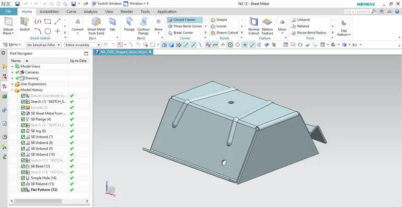
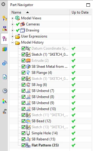
Full Fledged Feature tree
9. Modelled Components:
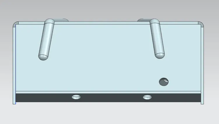 Front view
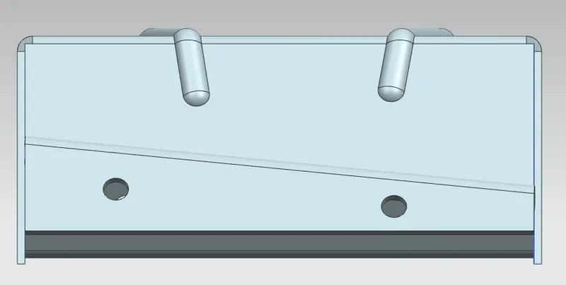 Rear view
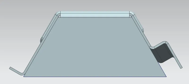 Side view
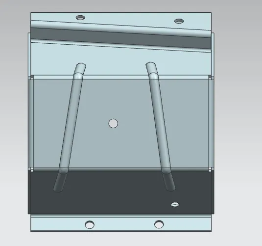
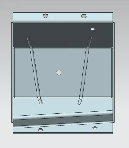
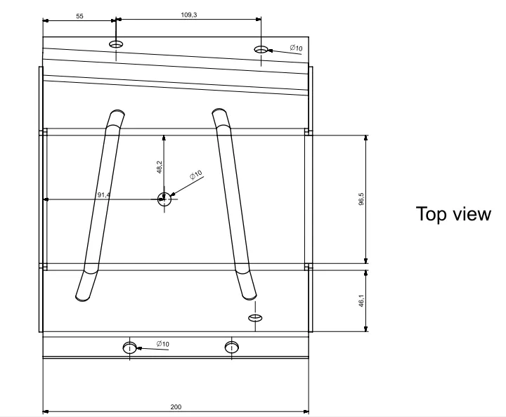
Top view Bottom view
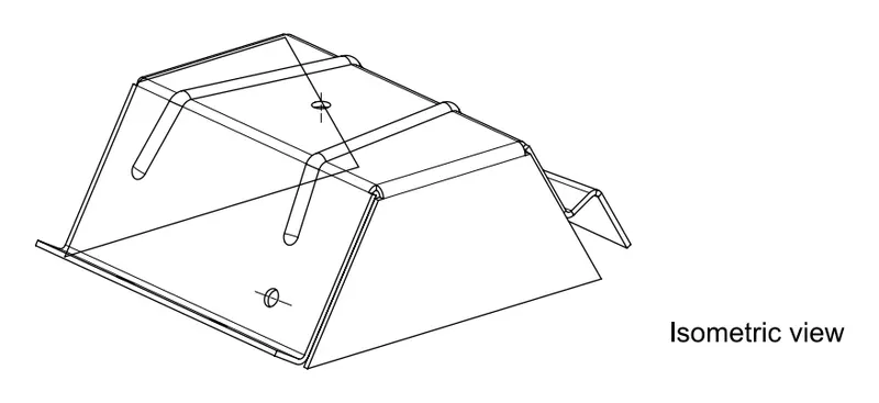
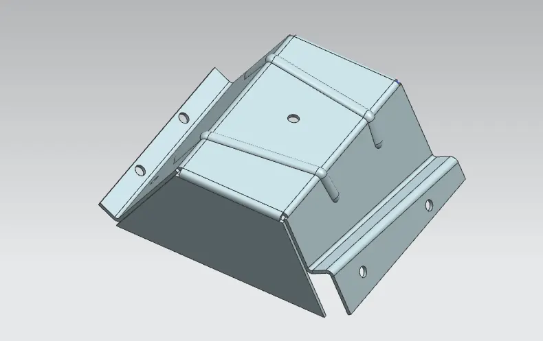 Isometric view
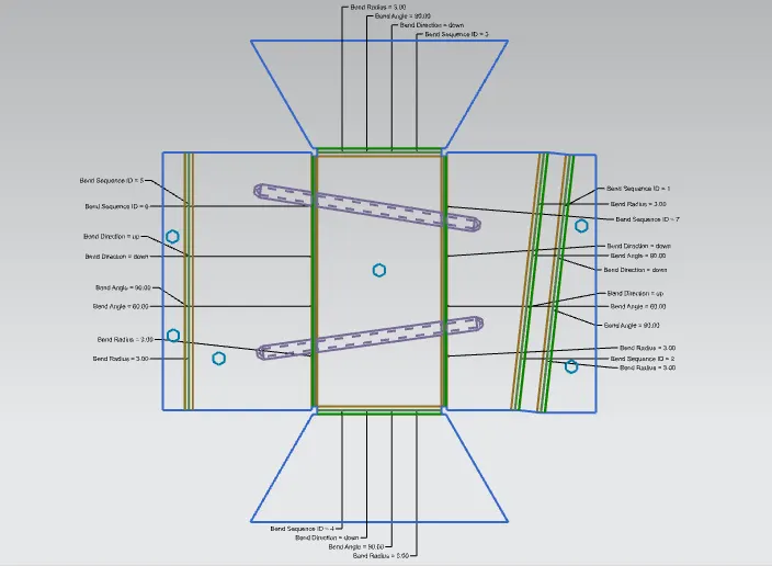 Flat Pattern view
10.Drafting:
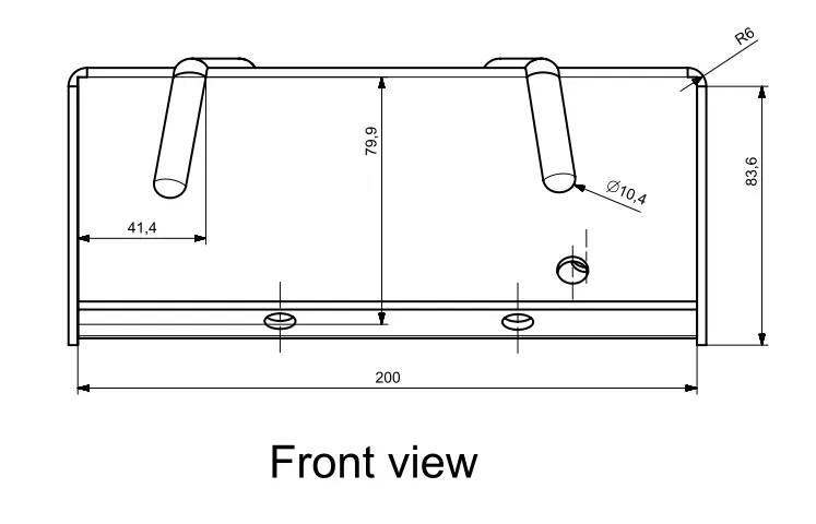
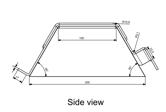
11. Conclusion:
The design and modelling of odd shaped enclosure (Sheetmetal) has been generated successfully, as per the dimensions provided in geometric model. The final product of the odd shaped enclosure tends to appear as the exact replica of the given model, and also the drafting is been carried out for various orientation. The NX CAD tends to make the design accomplishment easier within time constraint for the design engineer.