Cyclone Separator Challenge
Aim
To simulate anthracite particle-based cyclone separator with varying particle size from one micron to five microns with same particle velocity and inlet air velocity that is flow velocity, Also this particle velocity and flow velocity are varied from one to five with same five microns i.e. uniform particle size, this simulation results for pressure drop and separation efficiency of cyclone separator. All analysis is done only on only one design of cyclone separator. cyclon separator has a hydraulic diameter of 71.088mm and inlet area as a 5616-millimetre square. This cyclone separator has two phases as air and solid only.
Introduction to cyclone separator and models
Cyclone separator are used to segregate particulate matter from air or any other fluid ,That is why his comes under discrete phase modelling which based on langrage based solver; with means of generating cyclone due to forming turbulent cyclone inside the device due to its unique size which introduce the fluid and particulate matter inside device with high tangential velocity which leads to increment in spiral circulation of fluid and thus cyclone is generated inside of which low pressure is generated due to which lower density particle will be fed out or if there are varying density particle’s then; from central axis of cyclone the spiral spinning particle are distributed like from lower density particle to higher density particle , which are near to wall of cyclone separator device ,And higher density or larger particle travels towards the gravitational field because they have difficulties to follow vortex; This particles likely to be distributed nearer to wall; because they are following this spiral circulatory path tightly which generated inside the device.
Applications of cyclone separator have numerous in wheat husk industries, rice husk removing or polishing industries, cement industries, oil and gas industries, vacuum cleaner, chemical industries and coal industries etc.
Analysis
1) Geometry
2) Meshing
3) Setup and solving
4) Post-processing
1) Geometry
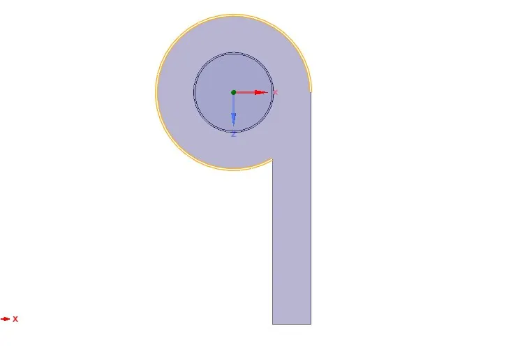
Below images show the volume of fluid is extracted from, for analysis
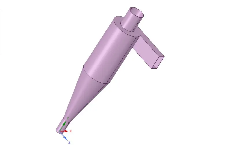
Below image shows the volume of fluid extracted
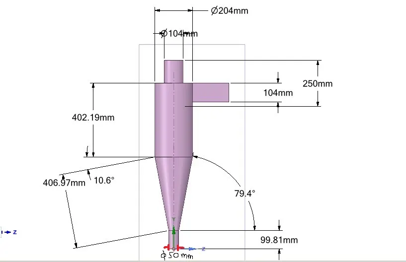
Dimensions
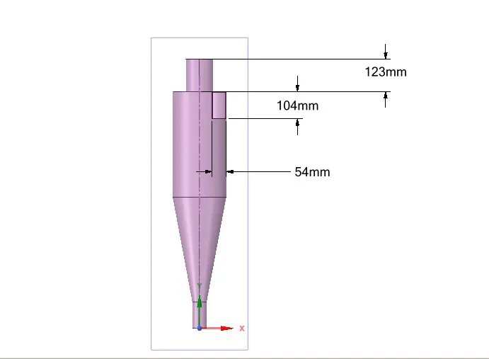
top view
2) Meshing
-Below image shows meshing is done by assembly cut cell mesh method (details of meshing are given afterwards)
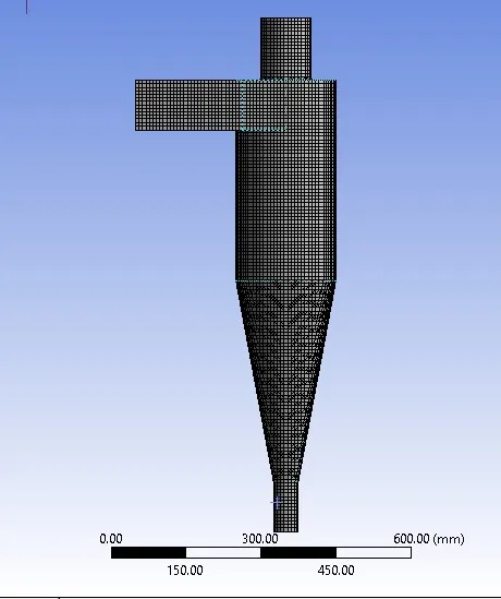
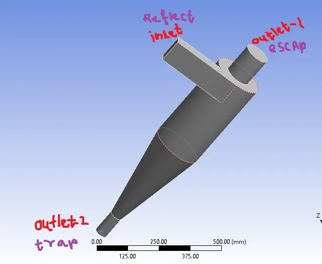
Boundaries’ are inlet, outlet 1 and outlet 2
3) Setup
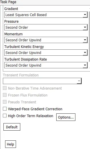
-steady-state gravity is enabled 9.81 m/s
-k-epsilon RNG based swirl dominated flow is setup for analysis
Materials
- injection material anthracite has density of 1550 kg/m^3
- air has a density of 1.225 kg/m^3 and viscosity of 1.788e-5 kg/m-s
-wall material s as default aluminium as 2719 kg/m^3
DPM setting
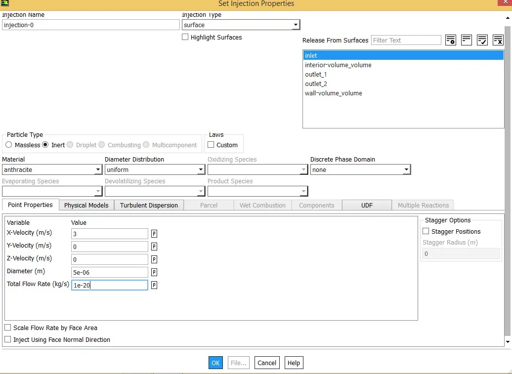
-discrete phase surface injection of anthracite with uniform diameter distribution particles are set. Below shown five microns as particle size (spherical particles)
- 3 m/s particle velocity and inlet flow velocity as 3 m/s asset
Below image shows injection setting
Inlet and wall:- DPM Reflect
Outlet(Top):-DPM Escape
Outlet(Bottom/dustbin) - DPM Trap
3) Solutions and post-processing
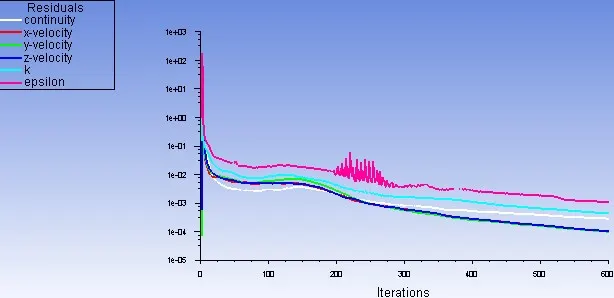
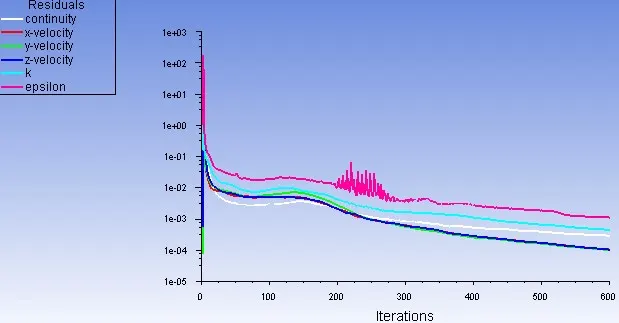
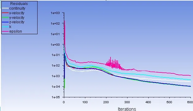
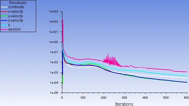
3.1.1 One micron to five micron residual plots for 600 iterations for particle velocity and inlet flow velocity as 3m/s
One micron
two micron
three micron
four micron
five micron
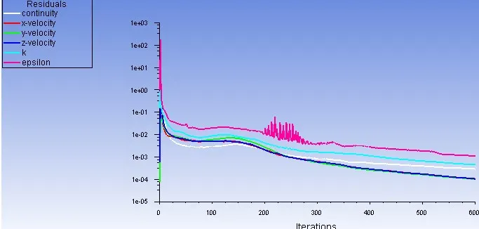
From the above plots, its observe that solution converged well
3.1.2 One micron to five-micron velocity contours for particle velocity and inlet flow velocity as 3m/s
One micron and two micron

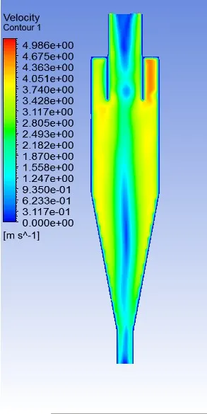
three microns and four micron
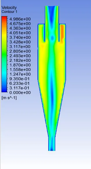
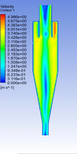
five micron
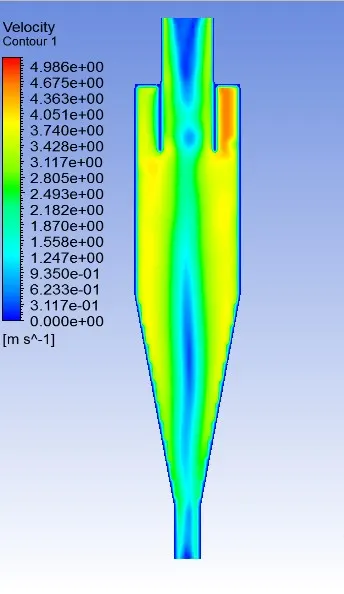
from all the above plots its observe that velocity contours are the same for varying particle size and also this velocity increases from mid axis to wall but at the wall, velocity is zero and thus this leads to centrifugal increased force so that heavier particles near to the wall of cyclone
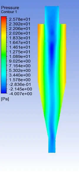
3.1.3 One micron to five-micron pressure contours for particle velocity and inlet flow velocity as 3m/s
One micron and two micron
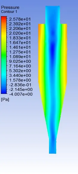
three microns and four micron
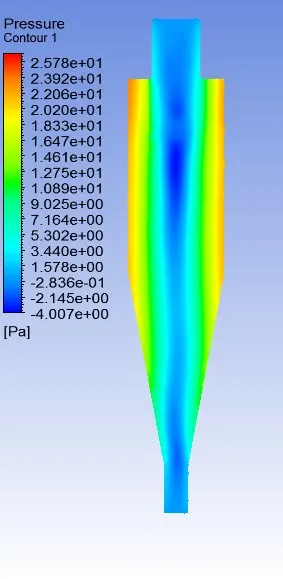
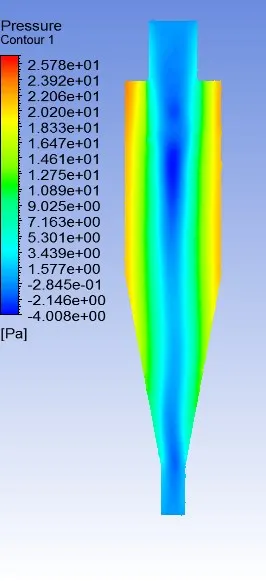
five micron
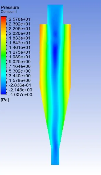
from all the above plots its observe that pressure contours are the same for varying particle size
3.2.1 Particle velocity and inlet flow velocity from one to five for particle diameter as five microns (residual plots 600 iterations)
Particle velocity and inlet flow velocity from one for particle diameter as five microns
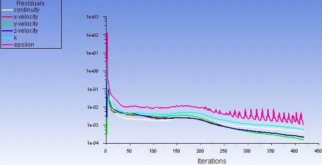
Particle velocity and inlet flow velocity from two for particle diameter as five microns
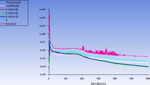
Particle velocity and inlet flow velocity from three for particle diameter as five microns
Particle velocity and inlet flow velocity from four for particle diameter as five microns
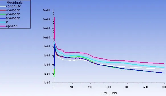
Particle velocity and inlet flow velocity from five for particle diameter as five microns
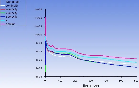
from above residuals, its observe that solution is converged well
3.2.2 Particle velocity and inlet flow velocity from one to five for particle diameter as five microns (velocity contours)
Particle velocity and inlet flow velocity from one for particle diameter as five microns and
Particle velocity and inlet flow velocity from two for particle diameter as five microns
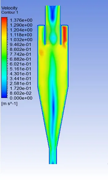
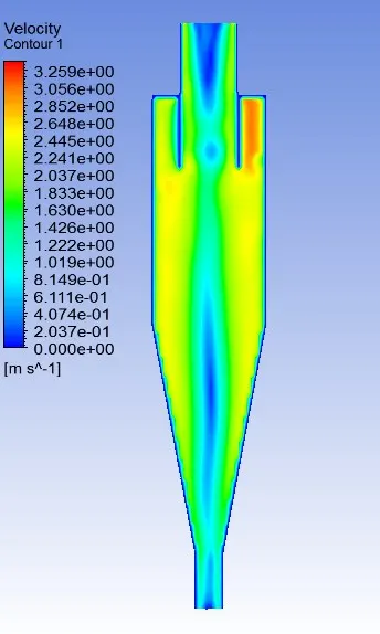
Particle velocity and inlet flow velocity from three for particle diameter as five microns and
Particle velocity and inlet flow velocity from four for particle diameter as five microns
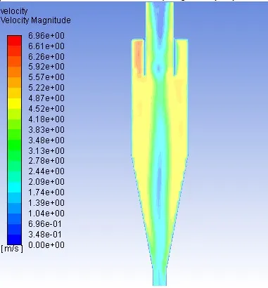
Particle velocity and inlet flow velocity from five for particle diameter as five microns
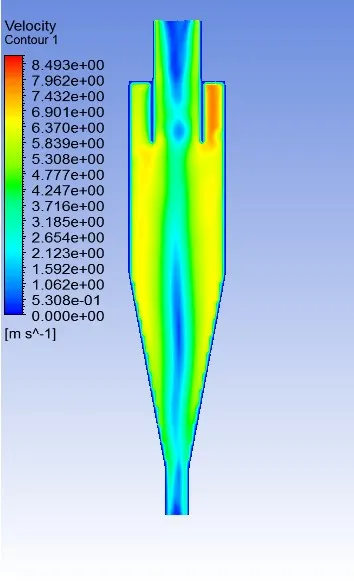
from above its observed that velocity increases from mid axis to wall but at the wall, velocity is zero and thus this leads to centrifugal increased force so that heavier particles near to the wall of the cyclone.
3.2.3 Particle velocity and inlet flow velocity from one to five for particle diameter as five microns (pressure contours)
Particle velocity and inlet flow velocity from one for particle diameter as five microns and
Particle velocity and inlet flow velocity from two for particle diameter as five microns
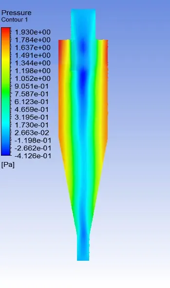
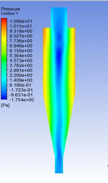
Particle velocity and inlet flow velocity from three for particle diameter as five microns and
Particle velocity and inlet flow velocity from four for particle diameter as five microns
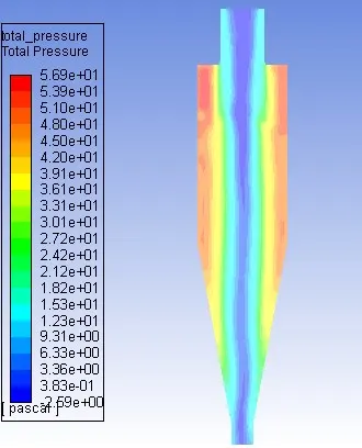
Particle velocity and inlet flow velocity from five for particle diameter as five microns
from above contours, it's observed that at mid of cyclone device low-pressure area is generated and thus lower density particle may attract to this area and that may try to escape if varying diameter particles are injected.
3.3 Particle velocity and inlet flow velocity three, particle diameter as five microns,
CONTOUR OF vortex region coloured by radial velocity and particle track coloured by total pressure and
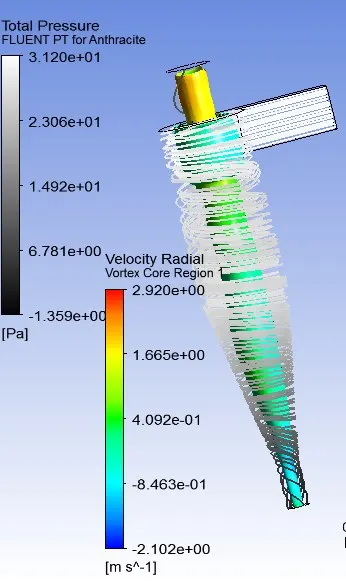
3.3 Particle velocity and inlet flow velocity three, particle diameter as five microns,
the plot of the central axis of the cyclone as y vs x-axis vs velocity magnitude
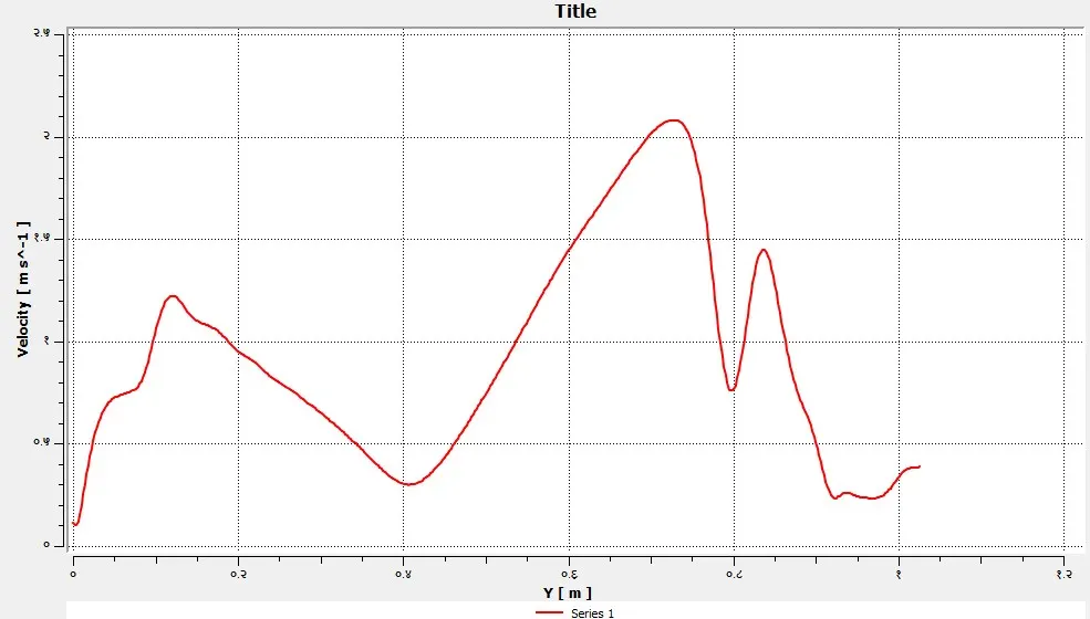
from the above plots, its observe that at 0.4m velocity gets lower.
Below table shows
Table 1 as Particle velocity and inlet flow velocity one to five, particle diameter as five microns separator efficiency and total pressure as pressure drop inside
Table 2 as Particle velocity and inlet flow velocity three, particle diameter as one to five microns separator efficiency and total pressure as pressure drop inside
| velocity (5 microns) TABLE 1 | number tracked | escaped | aborted | trapped | evaporated | incomplete | incomplete_parallel | separator efficiency (escape/track-incomplete)) | Pressure_drop_total pressure (pa) |
| 1 | 98 | 25 | 0 | 5 | 0 | 68 | 0 | 0.166666667 | 1.6703755 |
| 2 | 98 | 11 | 0 | 60 | 27 | 0 | 0.845070423 | 8.4077384 | |
| 3 | 98 | 2 | 0 | 96 | 0 | 0 | 0 | 0.979591837 | 19.947853 |
| 4 | 98 | 0 | 0 | 98 | 0 | 0 | 0 | 1 | 36.625645 |
| 5 | 98 | 1 | 0 | 97 | 0 | 0 | 0 | 0.989795918 | 58.453782 |
| particle in micron particle and flow velocity 3m/s | TABLE 2 | ||||||||
| particle size micron | number tracked | escaped | aborted | trapped | evaporated | incomplete | incomplete_parallel | separator efficiency (escape/track-incomplete)) | Pressure_drop_total pressure (pa) |
| 1 | 98 | 36 | 0 | 29 | 0 | 33 | 0 | 0.446153846 | 19.947862 |
| 2 | 98 | 33 | 0 | 64 | 0 | 1 | 0 | 0.659793814 | 19.947862 |
| 3 | 98 | 26 | 0 | 71 | 0 | 1 | 0 | 0.731958763 | 19.947862 |
| 4 | 98 | 10 | 0 | 88 | 0 | 0 | 0 | 0.897959184 | 19.947862 |
| 5 | 98 | 2 | 0 | 96 | 0 | 0 | 0 | 0.979591837 | 19.947862 |
tracked - particles entering from inlet surface
escaped - particles exist from outlet 1
traped- particles exist from outlet 2
incomplete- particles are in an infinite loop inside the cyclone device
Table 3 as Particle velocity and inlet flow velocity one to five, particle diameter as five microns total pressure as pressure drop inside volume and surface integral pressure at all boundaries
Table 4 as Particle velocity and inlet flow velocity three, particle diameter as one to five microns total pressure as pressure drop inside volume and surface integral pressure at all boundaries
| Mass-Weighted Average total pressure (pascal) | TABLE 3 | ||||
| 1 | 2 | 3 | 4 | 5 | particle and flow velocity |
| 1.6703755 | 8.4077384 | 19.947853 | 36.625645 | 58.453782 | volume_volume (from volume integral net) |
| 2.7984896 | 13.262835 | 31.036168 | 56.553342 | 89.779541 | inlet |
| n/a | 8.8112074 | 20.929676 | 38.456164 | 61.417318 | interior-volume_volume |
| 0.48117847 | 2.4611287 | 5.9128401 | 11.05855 | 17.598428 | outlet_1 |
| 0.263733 | 1.2377126 | 2.7905491 | 4.9896729 | 7.8270038 | outlet_2 |
| 1.6014935 | 8.8082998 | 20.922321 | 38.442375 | 61.394741 | net (from surface integrals) |
| particle in micron particle and flow velocity 3m/s | TABLE 4 | ||||
| 1 | 2 | 3 | 4 | 5 | particle in micron size (particle and flow velocity 3m/s) |
| 19.947862 | 19.947862 | 19.947862 | 19.947862 | 19.947862 | volume_volume (from volume integral net) |
| 31.036177 | 31.036177 | 31.036177 | 31.036177 | 31.036177 | inlet |
| 20.929685 | 20.929685 | 20.929685 | 20.929685 | 20.929685 | interior-volume_volume |
| 5.9128423 | 5.9128423 | 5.9128423 | 5.9128423 | 5.9128423 | outlet_1 |
| 2.7905509 | 2.7905509 | 2.7905509 | 2.7905509 | 2.7905509 | outlet_2 |
| 20.92233 | 20.92233 | 20.92233 | 20.92233 | 20.92233 | net (from surface integrals) |
some calculations
inlet volumetric flow as = 104mm*54mm*3m/s = 16848 cubic millimetre/sec
hydraulic diameter as 71.0 mm
outlet 2 areas as 16.848 square meter
below Matlab code is given to calculate number of turns and 50% cut side diameter for 3m/s as 7.17 micron
as cut side diameter increases the collection efficiency decreases and that is why collection efficiency of 4m/s is good
close all
clear all
clc


% for velocity 3m/s

H=0.104; %height inlet
lp=0.40219;  %lenght of cyclone body
lc=0.40011;   %lenght of cyclone cone body
nue=1.7886e-5;     %gas viscosity
W=0.054;       % width inlet
D=0.204;        % diameter of cyclone body
vi=3;         % inlet velocity
rhog=1.224;     % rho of gas
rhop=1550;       % rho of particle
De=0.104; %gas exit
ne=(1/H)*(lp+(lc/2)); % number of turns
dpc=((9*nue*W)/(2*pi*ne*vi*(rhop-rhog)))^(1/2); % 50 percentage cut point diametre
dt=(pi*D*ne)/vi;      % gas residence time

Vt=W/dt;     % Particle Drift Velocity
Conclusion
Hear only steady-state simulation is done on particle size change with same inlet flow and particle velocity and for five microns with varying inlet flow and particle velocity. Results of separation efficiency are calculated is best for a velocity of four meters per second with a five-micron diameter of the particle because as cut side diameter increases the collection efficiency decreases and that is why collection efficiency of 4m/s is good.
Scope
The transient simulation gives a better result, also inflation layer is not added by adding it in a cut cell method of meshing it will capture proximity in a good sense. Also, the grid dependency test is not preset above.
REFERENCES
2) https://www.sciencedirect.com/science/article/pii/S0307904X06000291
4) https://www.researchgate.net/publication/312160127_Design_and_fabrication_of_cyclone_separator
5) https://nptel.ac.in/content/storage2/courses/103103027/pdf/mod5.pdf