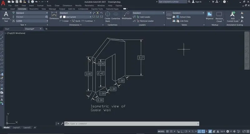
Creating a Floor plan, Footing detail and Isometric view using AutoCad
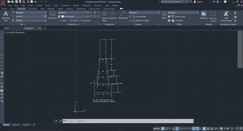
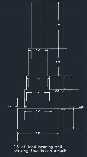
AIM: Creating the Cross Section of Load Bearing Wall showing Foundation details.
INTRODUCTION:
AutoCAD is a commercial computer-aided design (CAD) and drafting software application. Developed and marketed by Autodesk, AutoCAD was first released in December 1982 as a desktop app running on microcomputers with internal graphics controllers. Before AutoCAD was introduced, most commercial CAD programs ran on mainframe computers or minicomputers, with each CAD operator (user) working at a separate graphics terminal. AutoCAD is also available as mobile and web apps.
AutoCAD is used in industry, by architects, project managers, engineers, graphic designers, city planners and other professionals.
PROCEDURE:
Step 1: Open AutoCAD by clicking on the AutoCAD icon on the Desktop
Step 2: Start a new project by clicking Ctrl + N on the keyboard. A "Create new drawing" dialogue box will appear.
Step 3: Choose Imperial Template and Decimal units
Step 4: Commands used are as follows:
Command:
Command: PL
PLINE
Specify start point: 1,1
Current line-width is 0.0000
Specify next point or [Arc/Halfwidth/Length/Undo/Width]: Position the cursor and enter distance 0.90
Specify next point or [Arc/Close/Halfwidth/Length/Undo/Width]: Position the cursor and enter distance 0.45
Specify next point or [Arc/Close/Halfwidth/Length/Undo/Width]: Position the cursor and enter distance 0.15
Specify next point or [Arc/Close/Halfwidth/Length/Undo/Width]: Position the cursor and enter distance 0.40
Specify next point or [Arc/Close/Halfwidth/Length/Undo/Width]: Position the cursor and enter distance 0.05
Specify next point or [Arc/Close/Halfwidth/Length/Undo/Width]: Position the cursor and enter distance 0.30
Specify next point or [Arc/Close/Halfwidth/Length/Undo/Width]: Position the cursor and enter distance 0.05
Specify next point or [Arc/Close/Halfwidth/Length/Undo/Width]: Position the cursor and enter distance 0.60
Specify next point or [Arc/Close/Halfwidth/Length/Undo/Width]: Position the cursor and enter distance 0.05
Specify next point or [Arc/Close/Halfwidth/Length/Undo/Width]: Position the cursor and enter distance 1
Specify next point or [Arc/Close/Halfwidth/Length/Undo/Width]: Position the cursor and enter distance 0.30
Specify next point or [Arc/Close/Halfwidth/Length/Undo/Width]: Position the cursor and enter distance 1
Specify next point or [Arc/Close/Halfwidth/Length/Undo/Width]: Position the cursor and enter distance 0.05
Specify next point or [Arc/Close/Halfwidth/Length/Undo/Width]: Position the cursor and enter distance 0.60
Specify next point or [Arc/Close/Halfwidth/Length/Undo/Width]: Position the cursor and enter distance 0.05
Specify next point or [Arc/Close/Halfwidth/Length/Undo/Width]: Position the cursor and enter distance 0.30
Specify next point or [Arc/Close/Halfwidth/Length/Undo/Width]: Position the cursor and enter distance 0.05
Specify next point or [Arc/Close/Halfwidth/Length/Undo/Width]: Position the cursor and enter distance 0.40
Specify next point or [Arc/Close/Halfwidth/Length/Undo/Width]: Position the cursor and enter distance 0.15
Specify next point or [Arc/Close/Halfwidth/Length/Undo/Width]: c
Command: L
LINE
Specify first point: Position the cursor and left click
Specify next point or [Undo]: Position the cursor and left click
Specify next point or [Undo]: *cancel*
Command: L
LINE
Specify first point: Position the cursor and left click
Specify next point or [Undo]: Position the cursor and left click
Specify next point or [Undo]: *cancel*
Step 5: Type command "save". A "Save drawing as" dialogue box will appear. Choose the directory and file name and click the save button.
RESULT:
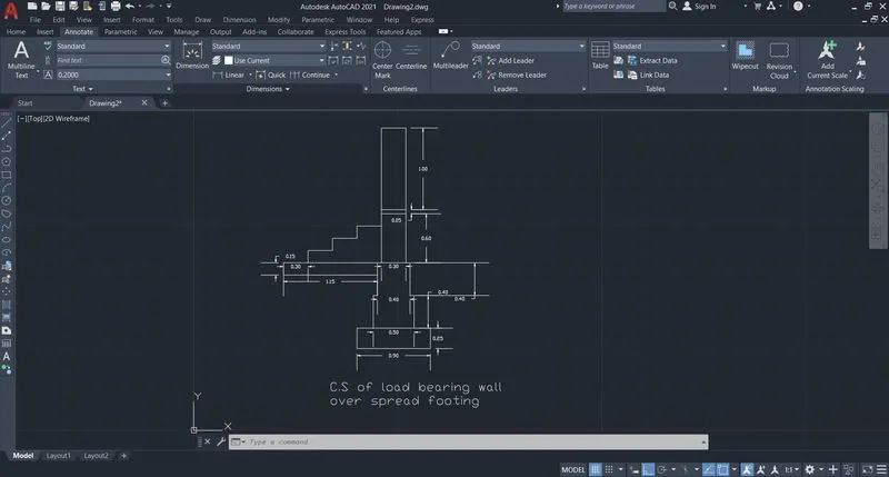
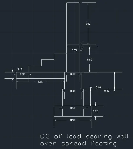
AIM: Creating the Cross Section of Load Bearing Wall over spread footing.
INTRODUCTION:
AutoCAD is a commercial computer-aided design (CAD) and drafting software application. Developed and marketed by Autodesk, AutoCAD was first released in December 1982 as a desktop app running on microcomputers with internal graphics controllers. Before AutoCAD was introduced, most commercial CAD programs ran on mainframe computers or minicomputers, with each CAD operator (user) working at a separate graphics terminal. AutoCAD is also available as mobile and web apps.
AutoCAD is used in industry, by architects, project managers, engineers, graphic designers, city planners and other professionals.
Isolated Spread Footing :
- This is the most widely recognized and most straightforward shallow foundation type, as this is the most economical type. They are typically utilized for shallow establishments to convey and spread concentrated burdens caused, for instance, by pillars or columns. They are generally used for ordinary buildings.
- Isolated footing comprises a foundation directly at the base of the segment. Generally, every section has its footing. They straightforwardly transfer the loads from the column to the soil. It might be rectangular, square, or roundabout.
- The size of the footing can be roughly calculated by dividing the total load at the column base by the allowable bearing capacity of the soil.
PROCEDURE:
Step 1: Open AutoCAD by clicking on the AutoCAD icon on the Desktop
Step 2: Start a new project by clicking Ctrl + N on the keyboard. A "Create new drawing" dialogue box will appear.
Step 3: Choose Imperial Template and Decimal units
Step 4: Commands used are as follows:
Command:
Command: L
LINE
Specify first point: 2,1
Specify next point or [Undo]: Position the cursor and enter distance 0.90
Specify next point or [Undo]: Position the cursor and enter distance 0.25
Specify next point or [Close/Undo]: Position the cursor and enter distance 0.2
Specify next point or [Close/Undo]: Position the cursor and enter distance 0.40
Specify next point or [Close/Undo]: Position the cursor and enter distance 0.05
Specify next point or [Close/Undo]: Position the cursor and enter distance 0.40
Specify next point or [Close/Undo]: Position the cursor and enter distance 0.05
Specify next point or [Close/Undo]: Position the cursor and enter distance 0.60
Specify next point or [Close/Undo]: Position the cursor and enter distance 0.05
Specify next point or [Close/Undo]: Position the cursor and enter distance 1
Specify next point or [Close/Undo]: Position the cursor and enter distance 0.30
Specify next point or [Close/Undo]: Position the cursor and enter distance 1
Specify next point or [Close/Undo]: Position the cursor and enter distance 0.05
Specify next point or [Close/Undo]: Position the cursor and enter distance 0.60
Specify next point or [Close/Undo]: Position the cursor and enter distance 0.05
Specify next point or [Close/Undo]: Position the cursor and enter distance 0.40
Specify next point or [Close/Undo]: Position the cursor and enter distance 0.05
Specify next point or [Close/Undo]: Position the cursor and enter distance 0.40
Specify next point or [Close/Undo]: Position the cursor and enter distance 0.2
Specify next point or [Close/Undo]: c
Command: L
LINE
Specify first point: Position the cursor and left click
Specify next point or [Undo]: 0.85
Specify next point or [Undo]: 0.3
Specify next point or [Close/Undo]: 0.15
Specify next point or [Close/Undo]: 1.15
Specify next point or [Close/Undo]: *Cancel*
Command: L
LINE
Specify first point: Position the cursor and left click
Specify next point or [Undo]: 0.15
Specify next point or [Undo]: 0.30
Specify next point or [Close/Undo]: 0.15
Specify next point or [Close/Undo]: 0.30
Specify next point or [Close/Undo]: 0.15
Specify next point or [Close/Undo]: 0.30
Specify next point or [Close/Undo]: *Cancel*
Command: L
LINE
Specify first point: Position the cursor and left click
Specify next point or [Undo]: Position the cursor and left click
Specify next point or [Undo]: *Cancel*
Command: L
LINE
Specify first point: Position the cursor and left click
Specify next point or [Undo]: Position the cursor and left click
Specify next point or [Undo]: *Cancel*
Command: L
LINE
Specify first point: Position the cursor and left click
Specify next point or [Undo]: Position the cursor and left click
Specify next point or [Undo]: *Cancel*
Command: L
LINE
Specify first point: Position the cursor and left click
Specify next point or [Undo]: Position the cursor and left click
Specify next point or [Undo]: *Cancel*
Step 5: Type command "save". A "Save drawing as" dialogue box will appear. Choose the directory and file name and click the save button.
RESULT:
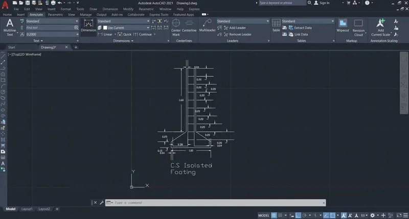
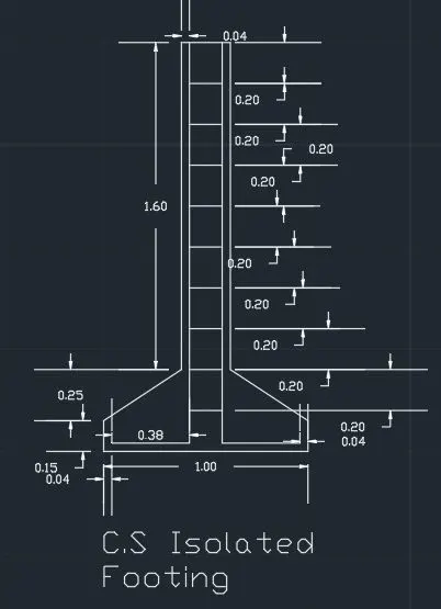
AIM: Creating the Cross Section of Isolated footing.
INTRODUCTION:
AutoCAD is a commercial computer-aided design (CAD) and drafting software application. Developed and marketed by Autodesk, AutoCAD was first released in December 1982 as a desktop app running on microcomputers with internal graphics controllers. Before AutoCAD was introduced, most commercial CAD programs ran on mainframe computers or minicomputers, with each CAD operator (user) working at a separate graphics terminal. AutoCAD is also available as mobile and web apps.
AutoCAD is used in industry, by architects, project managers, engineers, graphic designers, city planners and other professionals.
Isolated Spread Footing :
- This is the most widely recognized and most straightforward shallow foundation type, as this is the most economical type. They are typically utilized for shallow establishments to convey and spread concentrated burdens caused, for instance, by pillars or columns. They are generally used for ordinary buildings.
- Isolated footing comprises a foundation directly at the base of the segment. Generally, every section has its footing. They straightforwardly transfer the loads from the column to the soil. It might be rectangular, square, or roundabout.
- The size of the footing can be roughly calculated by dividing the total load at the column base by the allowable bearing capacity of the soil.
PROCEDURE:
Step 1: Open AutoCAD by clicking on the AutoCAD icon on the Desktop
Step 2: Start a new project by clicking Ctrl + N on the keyboard. A "Create new drawing" dialogue box will appear.
Step 3: Choose Imperial Template and Decimal units
Step 4: Commands used are as follows:
Command: L
LINE
Specify first point: 1,1
Specify next point or [Undo]: @0,0.15
Specify next point or [Undo]: @0.38,0.25
Specify next point or [Close/Undo]: @0,1.60
Specify next point or [Close/Undo]: 0.04
Specify next point or [Close/Undo]: Position the cursor and enter distance 0.16
Specify next point or [Close/Undo]: Position the cursor and enter distance 0.04
Specify next point or [Close/Undo]: @0,-1.60
Specify next point or [Close/Undo]: @0.38,-0.25
Specify next point or [Close/Undo]: @0,-0.15
Specify next point or [Close/Undo]: c
Command:
Command: L
LINE
Specify first point: Position the cursor and left click
Specify next point or [Undo]: Position the cursor and enter distance 1.96
Specify next point or [Undo]: Position the cursor and enter distance 0.38
Specify next point or [Close/Undo]: Position the cursor and enter distance 0.05
Specify next point or [Close/Undo]: *Cancel*
Command: L
LINE
Specify first point: Position the cursor and left click
Specify next point or [Undo]: Position the cursor and enter distance 1.96
Specify next point or [Undo]: Position the cursor and enter distance 0.38
Specify next point or [Close/Undo]: Position the cursor and enter distance 0.05
Specify next point or [Close/Undo]: *Cancel*
Command: O
OFFSET
Specify offset distance or [Through/Erase/Layer] <1.0000>: 0.2
Select object to offset or [Exit/Undo] : Select the object
Specify point on side to offset or [Exit/Multiple/Undo] : Choose the side
Select object to offset or [Exit/Undo] : Select the object
Specify point on side to offset or [Exit/Multiple/Undo] : Choose the side
Select object to offset or [Exit/Undo] : Select the object
Specify point on side to offset or [Exit/Multiple/Undo] : Choose the side
Select object to offset or [Exit/Undo] : Select the object
Specify point on side to offset or [Exit/Multiple/Undo] : Choose the side
Select object to offset or [Exit/Undo] : Select the object
Specify point on side to offset or [Exit/Multiple/Undo] : Choose the side
Select object to offset or [Exit/Undo] : Select the object
Specify point on side to offset or [Exit/Multiple/Undo] : Choose the side
Select object to offset or [Exit/Undo] : Select the object
Specify point on side to offset or [Exit/Multiple/Undo] : Choose the side
Select object to offset or [Exit/Undo] : Select the object
Specify point on side to offset or [Exit/Multiple/Undo] : Choose the side
Select object to offset or [Exit/Undo] : Select the object
Specify point on side to offset or [Exit/Multiple/Undo] : Choose the side
Select object to offset or [Exit/Undo] : *Cancel*
Step 5: Type command "save". A "Save drawing as" dialogue box will appear. Choose the directory and file name and click the save button.
RESULT:
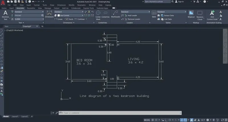
AIM: Creating the Line Diagram of a Two Bedroom Building.
INTRODUCTION:
AutoCAD is a commercial computer-aided design (CAD) and drafting software application. Developed and marketed by Autodesk, AutoCAD was first released in December 1982 as a desktop app running on microcomputers with internal graphics controllers. Before AutoCAD was introduced, most commercial CAD programs ran on mainframe computers or minicomputers, with each CAD operator (user) working at a separate graphics terminal. AutoCAD is also available as mobile and web apps.
AutoCAD is used in industry, by architects, project managers, engineers, graphic designers, city planners and other professionals.
PROCEDURE:
Step 1: Open AutoCAD by clicking on the AutoCAD icon on the Desktop
Step 2: Start a new project by clicking Ctrl + N on the keyboard. A "Create new drawing" dialogue box will appear.
Step 3: Choose Imperial Template and Decimal units
Step 4: Commands used are as follows:
Command: L
LINE
Specify first point: 1,2
Specify next point or [Undo]: @3.60<0
Specify next point or [Undo]: @0,-0.9
Specify next point or [Close/Undo]: @1<0
Specify next point or [Close/Undo]: @0,0.9
Specify next point or [Close/Undo]: @4.20<0
Specify next point or [Close/Undo]: @3.60<90
Specify next point or [Close/Undo]: @4.20<180
Specify next point or [Close/Undo]: @0.9<90
Specify next point or [Close/Undo]: @1<180
Specify next point or [Close/Undo]: @0.9<270
Specify next point or [Close/Undo]: @3.60<180
Specify next point or [Close/Undo]: c
Command: O
OFFSET
Current settings: Erase source=No Layer=Source OFFSETGAPTYPE=0
Specify offset distance or [Through/Erase/Layer] <1.0000>: 0.30
Select object to offset or [Exit/Undo] : Select the object
Specify point on side to offset or [Exit/Multiple/Undo] : Choose the side
Select object to offset or [Exit/Undo] : Select the object
Specify point on side to offset or [Exit/Multiple/Undo] : Choose the side
Select object to offset or [Exit/Undo] : Select the object
Specify point on side to offset or [Exit/Multiple/Undo] : Choose the side
Select object to offset or [Exit/Undo] : Select the object
Specify point on side to offset or [Exit/Multiple/Undo] : Choose the side
Select object to offset or [Exit/Undo] : *Cancel*
Command: L
LINE
Specify first point: Position the cursor and left click
Specify next point or [Undo]: @1.80<270
Specify next point or [Undo]: *Cancel*
Command: L
LINE
Specify first point: Position the cursor and left click
Specify next point or [Undo]: @0.90<90
Specify next point or [Undo]: *Cancel*
Step 5: Type command "save". A "Save drawing as" dialogue box will appear. Choose the directory and file name and click the save button.
RESULT:
AIM: Creating the Isometric view of Gable Wall.
INTRODUCTION:
AutoCAD is a commercial computer-aided design (CAD) and drafting software application. Developed and marketed by Autodesk, AutoCAD was first released in December 1982 as a desktop app running on microcomputers with internal graphics controllers. Before AutoCAD was introduced, most commercial CAD programs ran on mainframe computers or minicomputers, with each CAD operator (user) working at a separate graphics terminal. AutoCAD is also available as mobile and web apps.
AutoCAD is used in industry, by architects, project managers, engineers, graphic designers, city planners and other professionals.
Gable Wall: A gable is a section of wall located at the end of a pitched roof, between the edges of the intersecting pitches. It is usually triangular and extends from the eaves to the ridge, although the shape and detailing depends on the particular structural system used for the roof.
PROCEDURE:
Step 1: Open AutoCAD by clicking on the AutoCAD icon on the Desktop
Step 2: Start a new project by clicking Ctrl + N on the keyboard. A "Create new drawing" dialogue box will appear.
Step 3: Choose Imperial Template and Decimal units
Step 4: Commands used are as follows:
Command: ds
DSETTINGS
Command: <Ortho on>
Command: L
LINE
Specify first point:
Specify next point or [Undo]: Position the cursor and enter distance 0.30
Specify next point or [Undo]: Position the cursor and enter distance 3
Specify next point or [Close/Undo]: Position the cursor and enter distance 0.30
Specify next point or [Close/Undo]: c
Command: <Isoplane Right>
Command: L
LINE
Specify first point:
Specify next point or [Undo]: Position the cursor and enter distance 1
Specify next point or [Undo]: Position the cursor and enter distance 2.42
Specify next point or [Close/Undo]: Position the cursor and enter distance 1
Specify next point or [Close/Undo]: Position the cursor and enter distance 2.42
Specify next point or [Close/Undo]: Position the cursor and enter distance 1
Specify next point or [Close/Undo]: Position the cursor and enter distance 3
Specify next point or [Close/Undo]: <Isoplane Left> Position the cursor and enter distance 0.30
Specify next point or [Close/Undo]: *Cancel*
Command: L
LINE
Specify first point:
Specify next point or [Undo]: Position the cursor and enter distance 1.5
Specify next point or [Undo]: Position the cursor and enter distance 0.30
Specify next point or [Close/Undo]: *Cancel*
Command: L
LINE
Specify first point: Position the cursor and left click
Specify next point or [Undo]: Position the cursor and left click
Specify next point or [Undo]: Position the cursor and left click
Specify next point or [Close/Undo]: *Cancel*
Command: L
LINE
Specify first point: Position the cursor and left click
Specify next point or [Undo]: Position the cursor and left click
Specify next point or [Undo]: Position the cursor and left click
Specify next point or [Close/Undo]: *Cancel*
Command:
Command: e
ERASE 1 found
Command: L
LINE
Specify first point: Position the cursor and left click
Specify next point or [Undo]: Position the cursor and enter distance 0.30
Specify next point or [Undo]: Position the cursor and left click
Specify next point or [Close/Undo]: *Cancel*
Command:
Command:
** STRETCH **
Specify stretch point or [Base point/Copy/Undo/eXit]:
Command:
Command:
** STRETCH **
Specify stretch point or [Base point/Copy/Undo/eXit]:
Command: Specify opposite corner or [Fence/WPolygon/CPolygon]: *Cancel*
Command: *Cancel*
Step 5: Type command "save". A "Save drawing as" dialogue box will appear. Choose the directory and file name and click the save button.
RESULT: