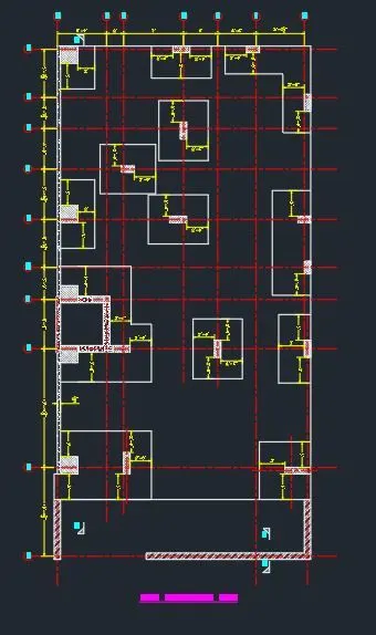
Creating a Wardrobe detailed drawing, Floor Plan, Kitchen Layout and Column Detail using AutoCad
AIM: Creating elevation and details of the wardrobe using AutoCAD.
INTRODUCTION:
AutoCAD is a commercial computer-aided design (CAD) and drafting software application. Developed and marketed by Autodesk, AutoCAD was first released in December 1982 as a desktop app running on microcomputers with internal graphics controllers. Before AutoCAD was introduced, most commercial CAD programs ran on mainframe computers or minicomputers, with each CAD operator (user) working at a separate graphics terminal. AutoCAD is also available as mobile and web apps.
AutoCAD is used in industry, by architects, project managers, engineers, graphic designers, city planners and other professionals.
The Wardrobe can be sketched using draw tools like Line tool, Offset tool, rectangle tool, arc tool etc., and it can be modified by trim tool, copy tool, rotate tool, erase tool etc.
PROCEDURE:
Step 1: Open AutoCAD by clicking on the AutoCAD icon on the Desktop
Step 2: Start a new project by clicking Ctrl + N on the keyboard. A "Create new drawing" dialogue box will appear.
Step 3: Choose Advance option and select decimal and precision to 0
Step 4: Commands used are as follows:
- Type 'UN' in the command prompt and set the units to decimal and set the precision as per the data given and insertion scale as millimeter
- Type 'Limit' and specify lower unit as 0,0 and upper unit as 10000,10000
- Type 'Zoom' and select All
Part1: Drawing Front Elevation:
- Type 'L' for line tool and draw a square with dimension 2800x2600
- Type 'O' for offset tool and specify the offset as 12mm
- Offset the top horizontal line and left vertical line inward
- Use Fillet tool to and fillet the intersected lines of the offset by taking radius as 0
- Type 'O' for offset tool and specify the offset as 488
- Select the top bottom horizontal line and offset it downwards
- Type 'O' for offset tool and specify the offset as 100
- Select the bottom horizontal line and offset it upwards
- Trim off the unwanted lines using Trim tool
- Type 'O' for offset tool and specify the offset as 1223
- Select the left vertical line and offset it on the right side of it
- Type 'O' for offset tool and specify the offset as 1200
- Select the left vertical offsetted line and offset it on the right side of it
- Trim off the unwanted lines using Trim tool
- Select the bottom horizontal line and click on the right grip and drag the grip to the right side to extend it a little
- Similarly do same in the left side
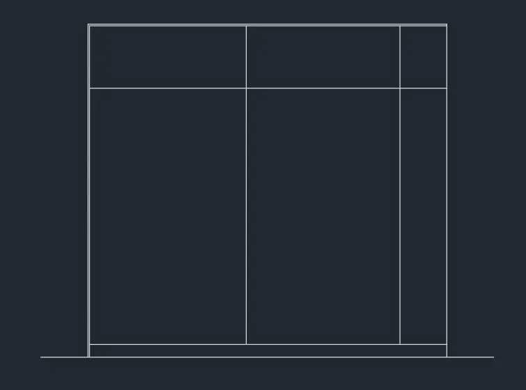
- Use Line tool to draw lines in the mid of the two boxes
- Use circle tool to draw the small circles
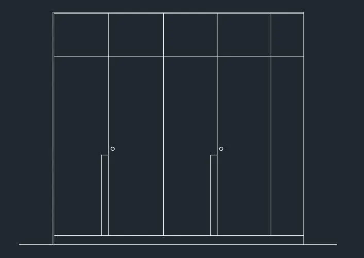
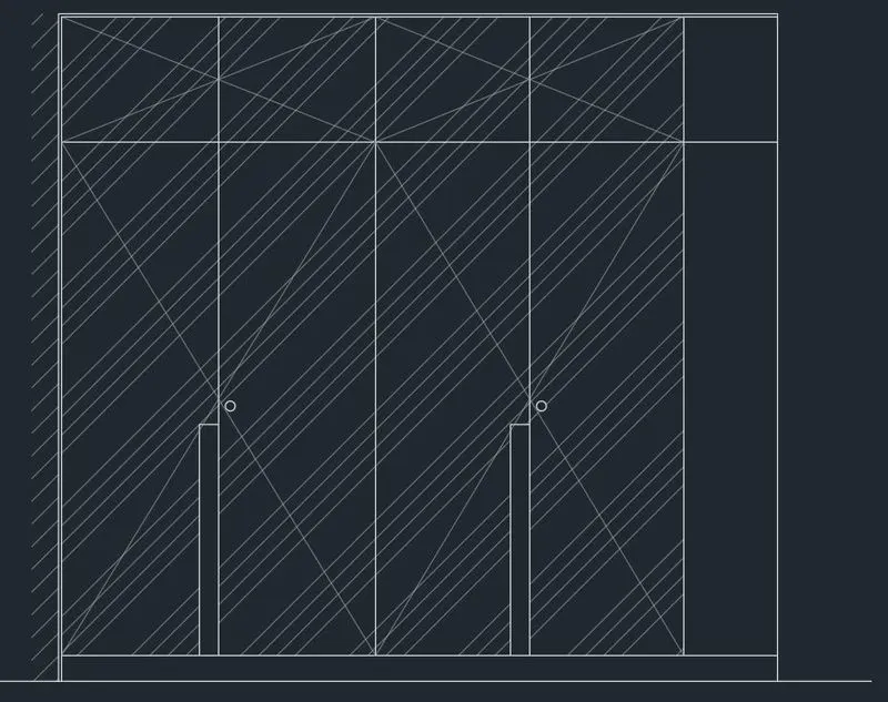
- Type 'Hatch' and select Ansi134 and select the hatch area
- Now select the hatched lines and right click and go to hatchedit and select the scale as 400 and transparency as 60
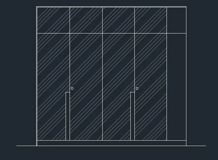
- Use Line tool to draw crossed line and define it in a new layer say 'Geometric lines'
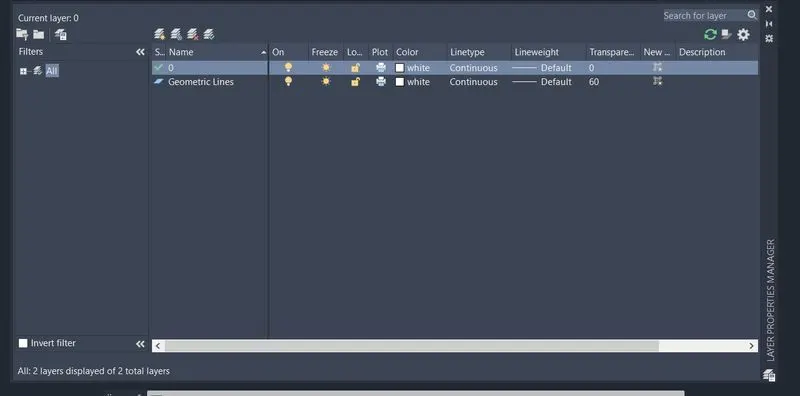
- Set the transparency of the layer to 60
- For hatching the wall surface, first make a closed boundary then with the hatch tool select Ansi131 and select the scale to 400 and transparency to 60
- With erase tool erase the previously drawn boundary for hatching
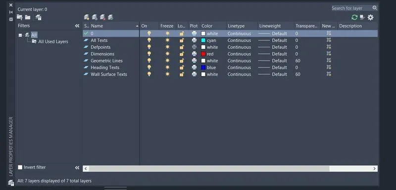
- Go to Layer properties and create new layer such as Dimensions and texts
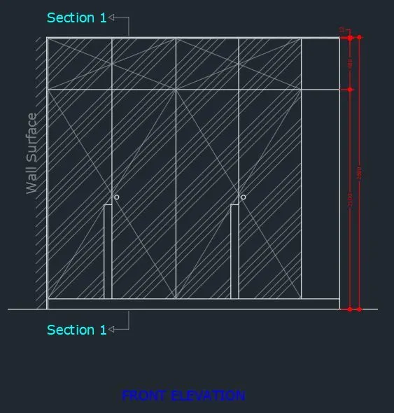
- Use Line tool to draw Section lines and mtext command to type the texts
- Using mtext command type all the texts in the front elevation drawing
- Using Dimlin command specify the dimensions
- Now assign the dimensions, texts to the corresponding layers
Part 2: Drawing Carcase Elevation
- Copy all the objects from the front elevation using 'CO' command and paste it in the right side of the front elevation drawing
- Trim off and erase the unwanted lines using Trim tool and Erase tool
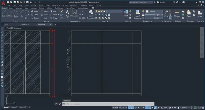
- Type 'O' for offset tool and specify the offset as 20
- Select the lines to offset inward
- Similarly offset the horizontal lines taking offset distance as 300 and 20 respectively
- Trim off the unwanted lines using Trim tool
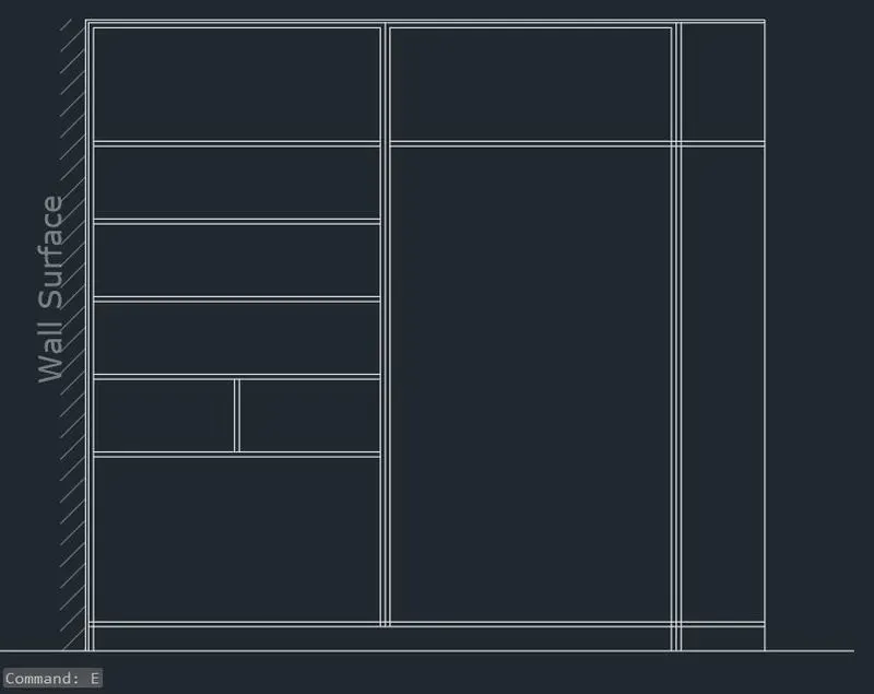
- Use the same Line tool and Offset tool to draw the right side of the drawing
- Using line tool draw the other components of the right side of the wardrobe
- Use Hatch Ansi137 and hatch Solid to hatch the baskets
- Go to hatchedit and adjust the scale
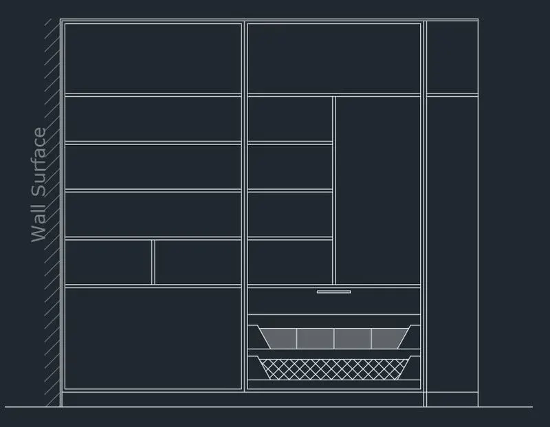
- Using Line tool, offset tool draw the right bottom part of the wardrobe
- Trim the unwanted lines using Trim tool
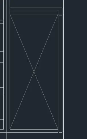
- Using Line tool, offset tool draw the right top part of the wardrobe
- Trim the unwanted lines using Trim tool
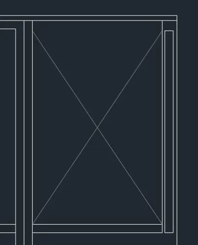
- Using rectangle tool draw the objects in the top left corner of the wardrobe
- Use offset tool and specify offset as 10 and offset the rectangle drawn
- Using Rectangle tool draw the other objects in the same area
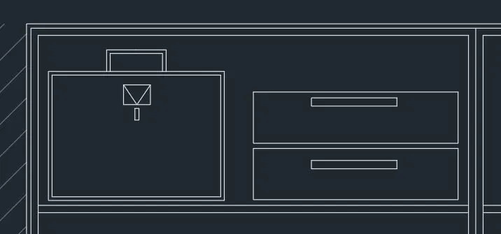
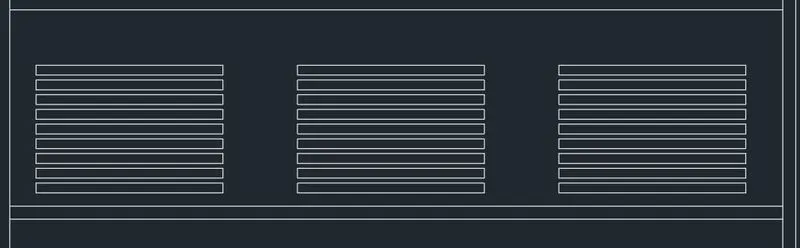
- Using rectangle tool draw a rectangle assuming the size
- Select the rectangle and choose rectangular array tool from the ribbon bar
- From the command area choose row as 3 and column as 9 and distance between column as 370
- Now by using Copy tool copy the rectangular array created and paste it in the respective boxes where similar objects has to be there
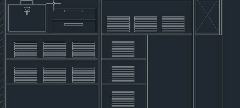
- Similarly using rectangle tool, arc tool and array tool draw the objects of the other wardrobe area
- Copy the object using Copy tool and paste in the respective area of the wardrobe
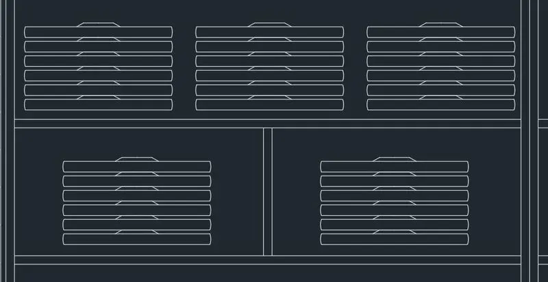
- Using Line tool, arc tool and offset tool draw the object in the bottom left box of the wardrobe
- Use 'TR' to trim off the unwanted lines
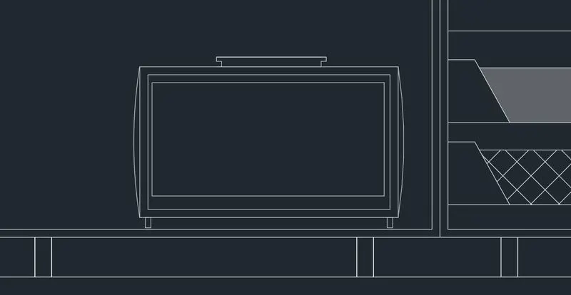
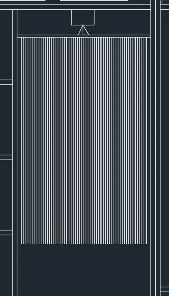
- For the hanger area draw a line with assumed length
- Now from the ribbon choose path array and select the line previously drawn
- Assume number of items as 70 and at a distance of 8
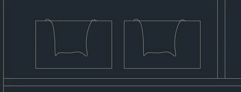
- With rectangle tool make a random size rectangle in the box just on the left bottom side of the hanger area
- Now with the Spline tool draw the cloth
- With the copy tool copy the entire object drawn and paste next to it
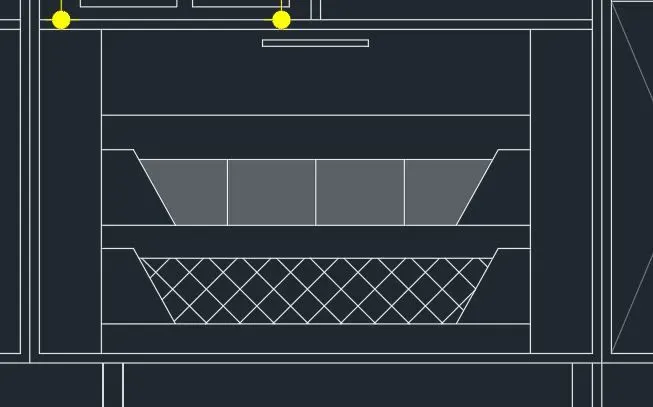
- Correction was needed in one part of the drawing. Following is the corrected sketch
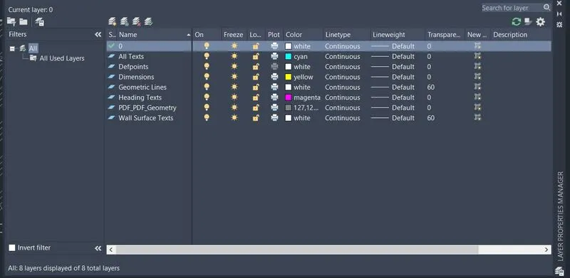
- Correct the layer colors for more visibility.
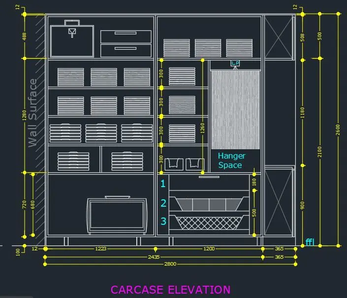
- Now that the sketching is completed, with the linear dimension tool and mtext or dtext command mark all the dimensions and texts
- Assign all texts and dimesions to the respective layers
Part 3: Side Elevation:
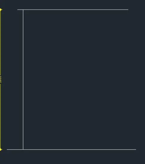
- Type 'L' for line tool and draw a vertical line just beside the carcase elevation
- Press esc to cancel the command
- Type 'L' again for line tool and draw a two line with reference to the extreme top and bottom horizontal line
- Press Esc to cancel the command
- With the Trim tool, trim off the unwanted lines
- Type 'O' for offset tool and offset the vertical line with offset distance 630 in the right side
- Similarly offset the four sides of the drawn figure with offset distance 20 inward
- Now with the trim tool trim off the unwanted lines
- Type 'O' for offset tool and offset the bottom horizontal line with offset distance 100 in the top side
- Type 'O' for offset tool and offset the bottom horizontal line with offset distance 900 in the top side
- Type 'O' for offset tool and offset the last offsetted horizontal line with offset distance 1180 in the top side
- Type 'O' for offset tool and offset the third bottom horizontal line with offset distance 20 in the bottom side
- Now with the trim tool trim off the unwanted lines
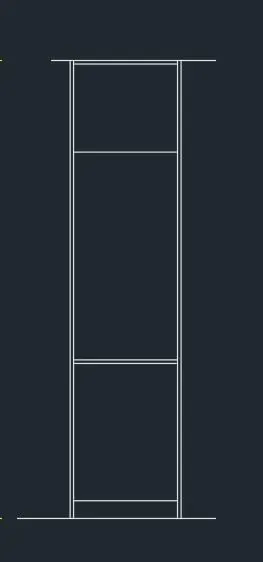
- Use the 'Hatch' command as previously used with similar scale and hatch the portion shown in the figure
- Or we can hatch the required area and match the properties of the hatched area with the previously hatched area with 'MA' command
- Now copy the text 'Wall Surface' and paste it in the recent drawing. Adjust the angle with rotate tool
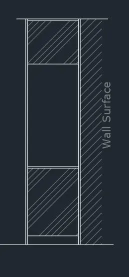
- Now draw the geometric lines with the line tool
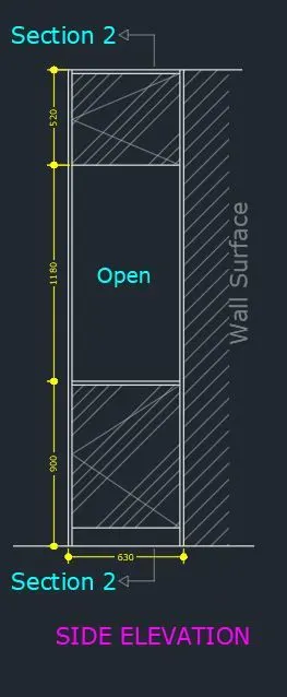
- Use mtext command to write texts in the requred area
- Scale the text of match the properties with the previous texts
- Use dimlin tool to specify the dimensions
- Copy the section line previously drawn and rename the text part as 'Section 2'
- Now assign all dimensions and texts to the corresponding layers
Part 4: Section 1:
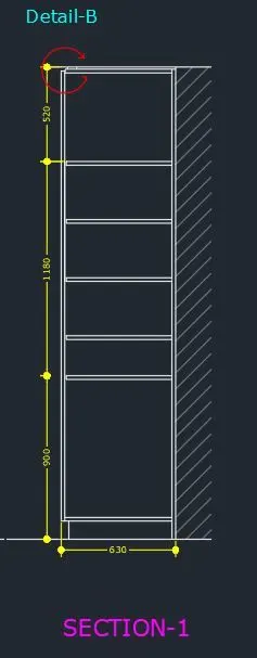
- Copy the entire drawing of the side elevation and paste it just right to it
- Erase all the objects which is unnecessary by using Erase tool
- Now using Line tool and Offset tool draw other aspects of the Section
- Use mtext command for writing texts
- Assign all the dimesnion and texts and other objects to corresponding layers
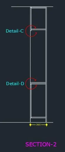
Part 5: Section 2:
- Using Line tool draw two horizontal lines taking reference of top and bottom horizontal lines of the previous drawing
- Now with Line tool Draw a vertical line intersecting these two horizontal lines
- Using Trim tool trim off the unwanted lines
- Type 'O' for offset tool and specify the offset as 365 and offset it in the right side of it
- Type 'O' for offset tool and specify the offset as 100
- Select the bottom horizontal line and offset it in the top side
- Similarly offset last offsetted line and both vertical line inward by taking offset distance as 20
- Offset the top horizontal line at an offset distance of 12 in downward direction
- Now Offset the last offsetted line downward by taking offset distance as 20
- Using Trim tool trim off the unwanted lines
- Similarly use the line tool and offset tool to draw other aspects of the drawing
- Use trim tool to trim off the unwanted lines
- Use dimlin and mtext to assign dimensions and texts
Part 6: Plan :
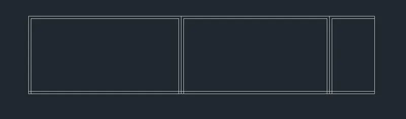
- Type 'L' for line tool and draw two vertical lines in the downward side by taking reference point of the two extreme opposite vertical lines of the Front elevation
- Similarly using line tool draw a horizontal line intersecting both previously drawn vertical lines
- Type 'O' for offset tool and offset the horizontal line drawn at a distance of 630 downward
- Using Trim tool trim off the unwanted lines

- Similarly using offset tool draw the other aspects of the drawing
- For doors use line tool and arc tool
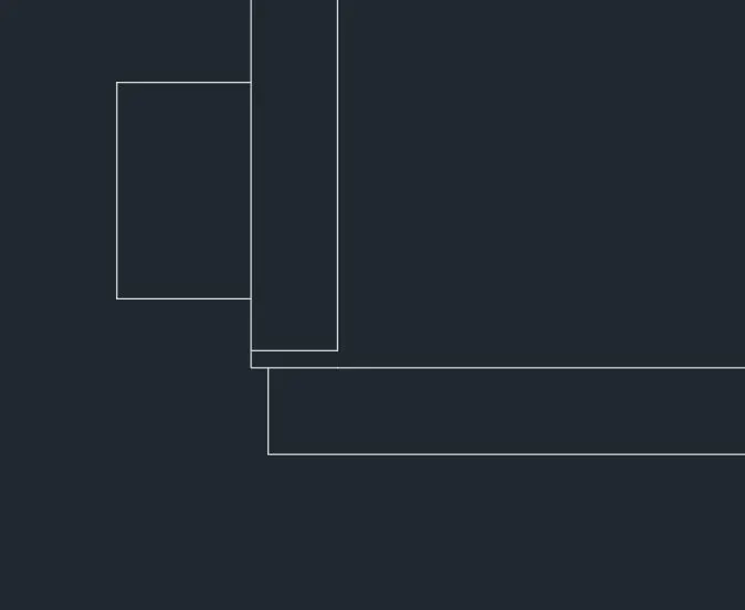
- By using line tool draw the doors of the wardrobe and rotate it at 45 degree using Rotate tool
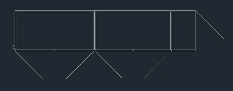
- To draw the arc click 'center, start and end' option in the arc option available in the ribbon bar
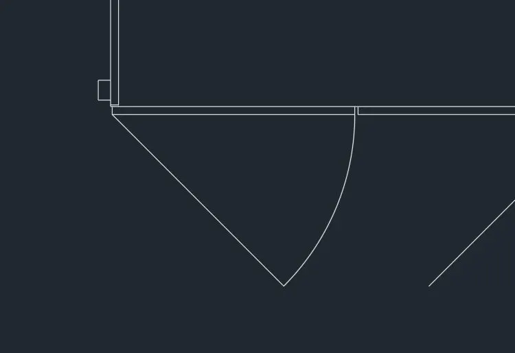
- Similarly follow the same procedure for other doors.
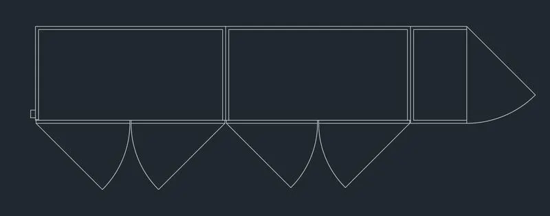
- Now using the hatch command hatch the wall area and match the properties with the similar hatched area
- Use copy tool to copy the 'wall surface' text from the above drawing and paste it in the required place
- Use dimlin and mtext command to specify the dimension and texts
- Now assign the dimension and texts to the corresponding layer
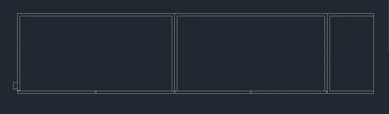
- And after overviewing the drawing and correcting it, following is the result drawing of the plan
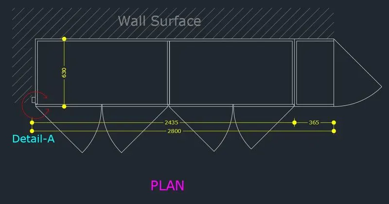
RESULT:
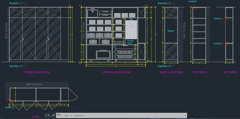
Following is the entire drawing properly sketched.
AIM: Creating a floor plan using AutoCAD.
INTRODUCTION:
AutoCAD is a commercial computer-aided design (CAD) and drafting software application. Developed and marketed by Autodesk, AutoCAD was first released in December 1982 as a desktop app running on microcomputers with internal graphics controllers. Before AutoCAD was introduced, most commercial CAD programs ran on mainframe computers or minicomputers, with each CAD operator (user) working at a separate graphics terminal. AutoCAD is also available as mobile and web apps.
AutoCAD is used in industry, by architects, project managers, engineers, graphic designers, city planners and other professionals.
The floor plan can be sketched using draw tools like Line tool, Offset tool, rectangle tool, arc tool etc., and it can be modified by trim tool, copy tool, rotate tool, erase tool etc.
PROCEDURE:
Step 1: Open AutoCAD by clicking on the AutoCAD icon on the Desktop
Step 2: Start a new project by clicking Ctrl + N on the keyboard. A "Create new drawing" dialogue box will appear.
Step 3: Choose Advance option and select decimal and precision to 0
Step 4: Commands used are as follows:
- Type 'UN' in the command prompt and set the units to decimal and set the precision as per the data given and insertion scale as millimeter
- Type 'Limit' and specify lower unit as 0,0 and upper unit as 10000,10000
- Type 'Zoom' and select All
- Type 'XL' for construction line tools and draw two construction lines vertical and horizontal
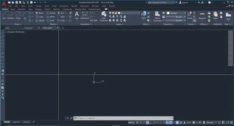
- We will begin the drafting starting from top to bottom
- Type 'O' for offset tool and specify the offset as 230 and offset the vertical and horizontal construction line inward
- Similarly with the offset tool offset the vertical line to 3880 in the positive x-direction
- Again Offset the last offsetted vertical line at a distance of 230
- Now offset the bottom horizontal line at a distance of 150 downward
- Similarly offset the last offsetted horizontal line at a distance of 4350 downward
- Again offset the last offsetted horizontal line at a distnance 230 downward
- Using Trim tool trim off the unwanted lines
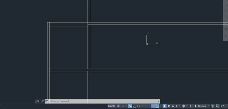
- Now offset all the vertical lines using offset tool by taking offset distance of respective rooms and walls in x-direction
- Using Trim Tool, trim off the unwanted lines
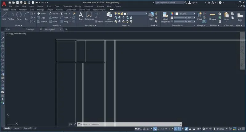
- Now offset all the horizontal lines using offset tool by taking offset distance of respective rooms and walls in y-direction
- Using Trim Tool, trim off the unwanted lines
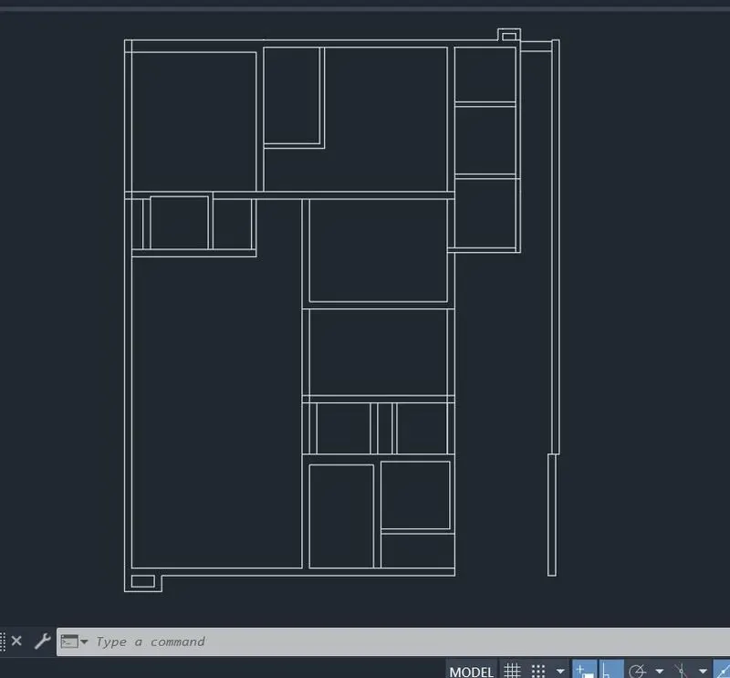
- Now using offset tool offset the door, windows and ventilators openings with assumed offset distance
- Using Trim tool, trim off the unwanted lines
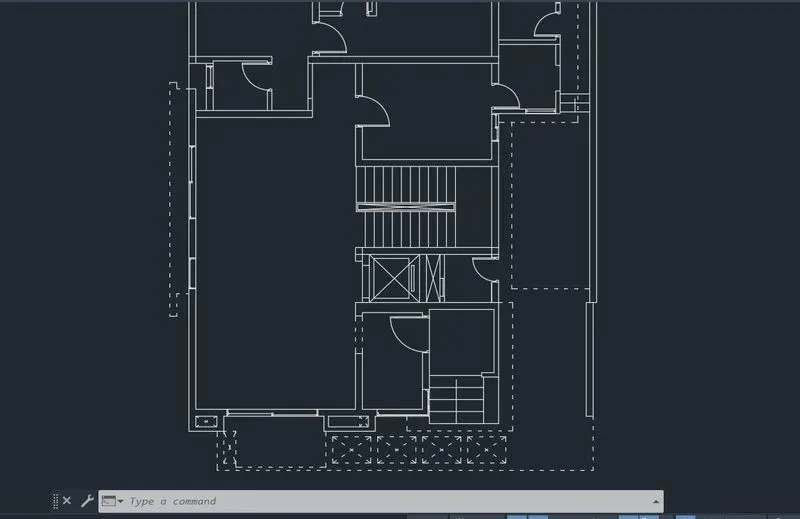
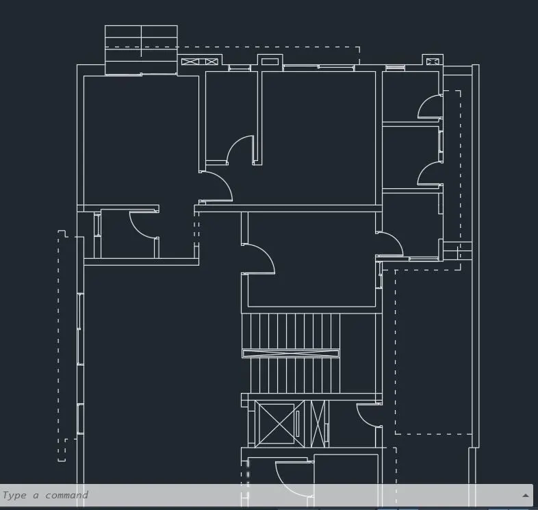
- Also by using line tool draw the doors and using arc tool draw the arc along with the doors
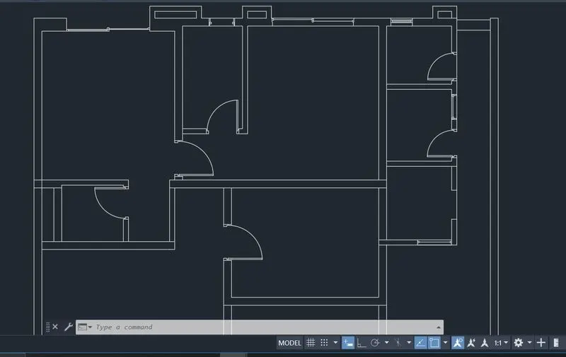
- There are different doors and one or two doors are of same dimensions, therefore we can copy and paste the similar doors.
- To fit the copied doors, we can modify it using mirror tool or rotate tool and then using move tool we can fit it in the respective place
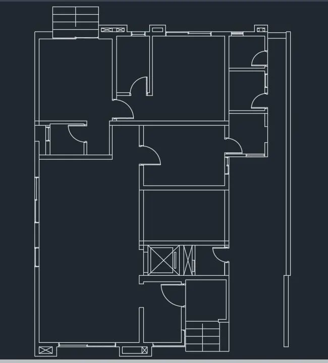
- To draw the staris we will use the offset tool and Line tool
- The offset distance taken is 300 as the tread is 300mm
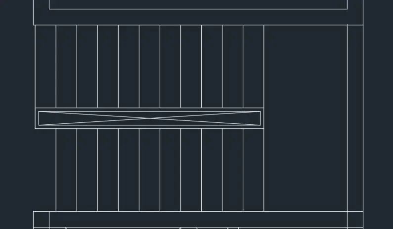
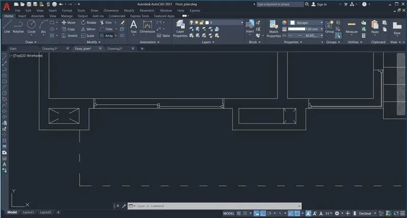
- Now to draw the exterior boundary use Line tool
- Load the line type 'ACAD_ISO03W100' from the ribbon bar and adjust the scale to 10
- Now Draft the exterior line
- Use 'MA' command to match the properties of the current drawn line with the previous drawn line wherever required
- Use Trim tool, to trim off the unwanted lines
- Using Circle tool and line tool draw the outdoor seating with canopy
- Use fillet tool, trim tool and mirror tool or polar array tool to modify and complete the outdoor seatings
- We can draw the seatings with canopy with random size and then we can scale it later

- Using Mtext command for texts in the drawing
- Scale the text using scaletext command
- Creating a new layer for texts
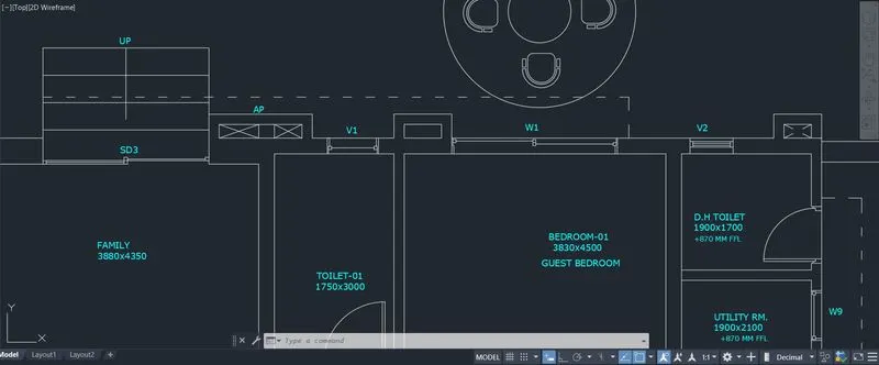
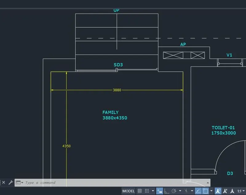
- Using Dimlin commnad specify the dimensions wherever required
- Scale the dimension through the Dimst command
- Creating a new layer for dimension and assigning all dimensions to the dimension layer
RESULT:
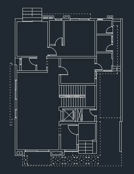
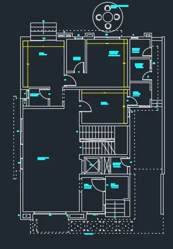
- Following is the floor plan without furniture details and hatching.
- To draw the plan major tools used are Line tool, offset tool, mtext tool, copy tool, mirror tool, rotate tool and array tool.
AIM: Creating a Kitchen Layout using AutoCAD.
INTRODUCTION:
AutoCAD is a commercial computer-aided design (CAD) and drafting software application. Developed and marketed by Autodesk, AutoCAD was first released in December 1982 as a desktop app running on microcomputers with internal graphics controllers. Before AutoCAD was introduced, most commercial CAD programs ran on mainframe computers or minicomputers, with each CAD operator (user) working at a separate graphics terminal. AutoCAD is also available as mobile and web apps.
AutoCAD is used in industry, by architects, project managers, engineers, graphic designers, city planners and other professionals.
The kitchen layout can be sketched using draw tools like Line tool, Offset tool, rectangle tool, arc tool etc., and it can be modified by trim tool, copy tool, rotate tool, erase tool etc.
PROCEDURE:
Step 1: Open AutoCAD by clicking on the AutoCAD icon on the Desktop
Step 2: Start a new project by clicking Ctrl + N on the keyboard. A "Create new drawing" dialogue box will appear.
Step 3: Choose Advance option and select decimal and precision to 0
Step 4: Commands used are as follows:
- Type 'UN' in the command prompt and set the units to decimal and set the precision as per the data given and insertion scale as millimeter
- Type 'Limit' and specify lower unit as 0,0 and upper unit as 10000,10000
- Type 'Zoom' and select All
- Type 'XL' for construction line tools and draw two construction lines vertical and horizontal
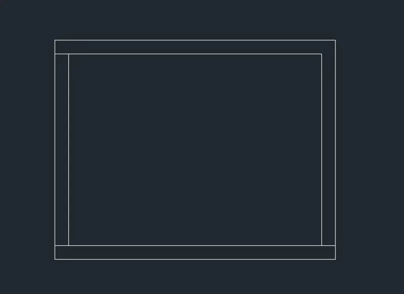
- Type 'O' for offset tool and offset both lines at a distance of 230
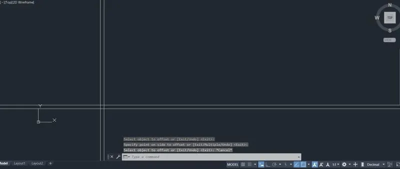
- Type 'O' for offset tool and offset the top horizontal line at a distance of 3200
- Type 'O' for offset tool and offset the previous offsetted horizontal line at a distance of 230
- Type 'O' for offset tool and offset the right vertical line at a distance of 4230
- Type 'O' for offset tool and offset the previous offsetted vertical line at a distance of 230
- Using Trim tool, trim off the unwanted lines
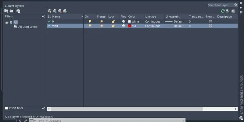
- Create a new layer from layer properties and name it "wall"
- Assign all the above drawn lines to layer wall
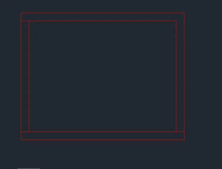
- Using Line tool and Offset tool draw the Door opening taking distance of the door opening as 1050 and other door opening as 850
- Draw the other components using arc tool
- Using Line tool and offset tool draw the window openings and other components also.
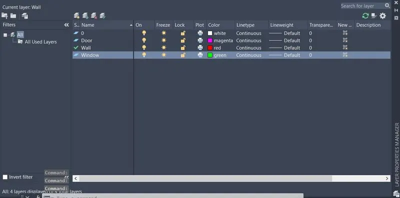
- Create a New Layers naming Door and Window from layer properties and assign the door objects to Door layer and window object to window layer
- Similarly do the same procedure for window openings
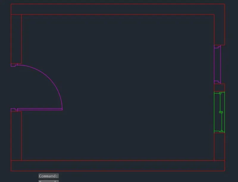
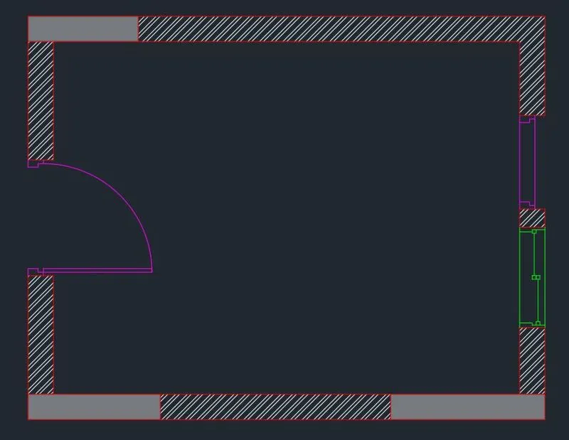
- Type 'Hatch' and seletc Ansi132 and click on the wall area.
- Type 'Hatchedit' and select the hatched area and set the scale to 200
- Type 'Hatch' and select Solid and click on the wall area
- Type 'Hatchedit' and select the hatched area and set the transparency to 60
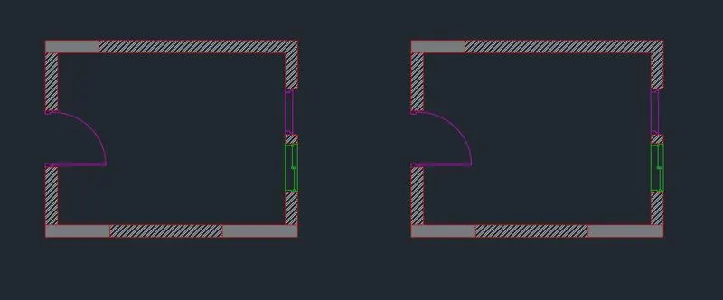
- Now copy whole object using copy tool and paste it right side of it. (this is done because the dimensions are same for the other plan)
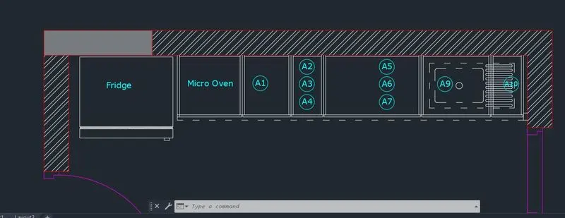
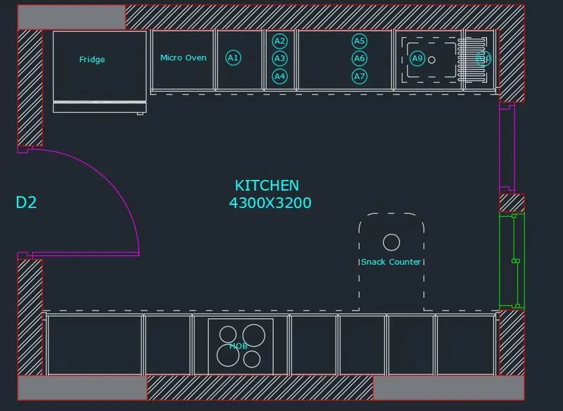
- Now using line tool and offset tool draw the kitchen equipments for the below counter plan.
- Trim off the unwanted lines using trim tool
- Distances are mentioned, therefore offset the lines in the following distances.
- Change the linetype wherever necessary from Linetype in the ribbon panel. Scale it to make it visible.

- Similarly using line tool and offset tool draw the other equipments of the below counter plan
- Use Circel tool and Line tool for the HOB area
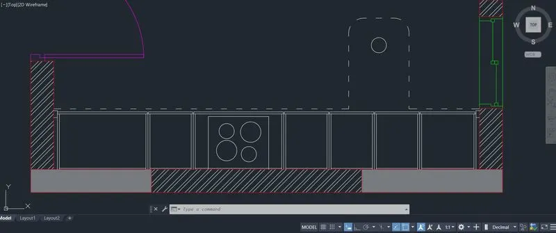
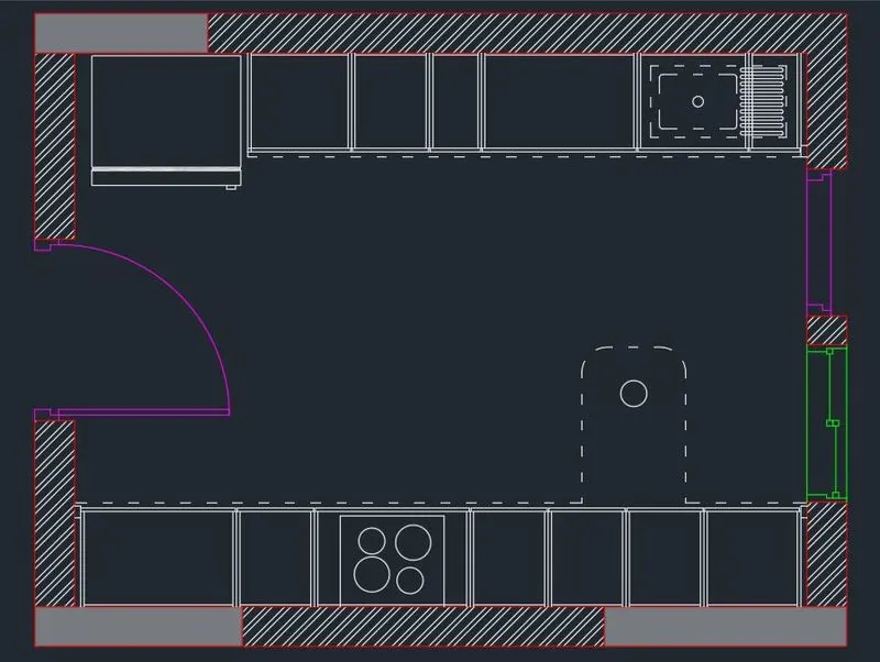
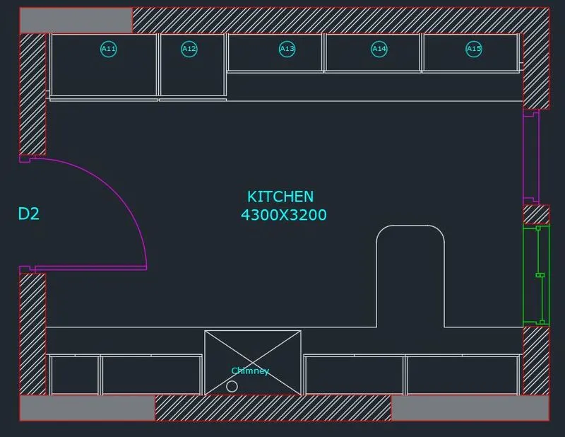
- Similarly using line tool and offset tool draw the other aspects of the 'Above counter plan'
- Use trim tool to trim off the unwanted lines
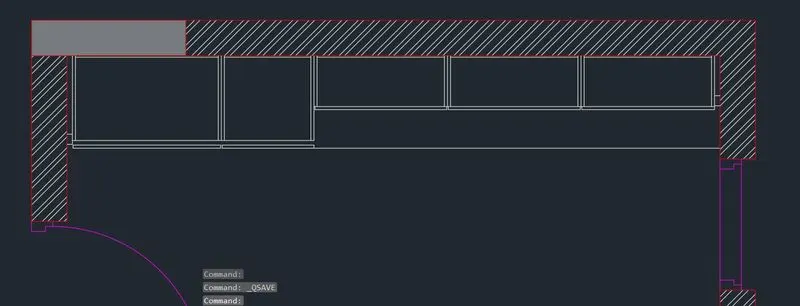
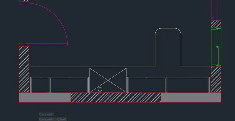
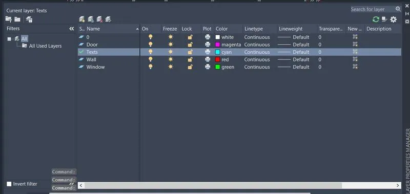
- Create a new layer and name it Texts. Choose this layer as current layer and with the mtext tool specify all the texts in the diagram
- Create a new layer and name it Dimesnions and set it to current.
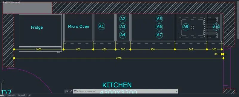
- Now using Dimlin command give proper dimension to the drawing
- Use Dimcontinue command for easy and quick dimensioning
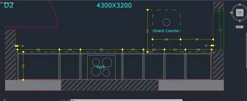
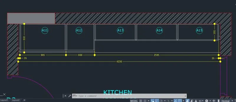
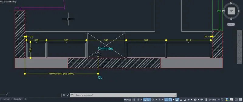
RESULT:
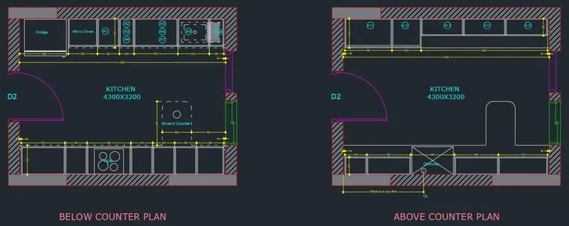
- Create a new layer naming Heading text and set it to current and with the mtext command write the drawing heading beneath the drawing.
- Following is the complete sketch.
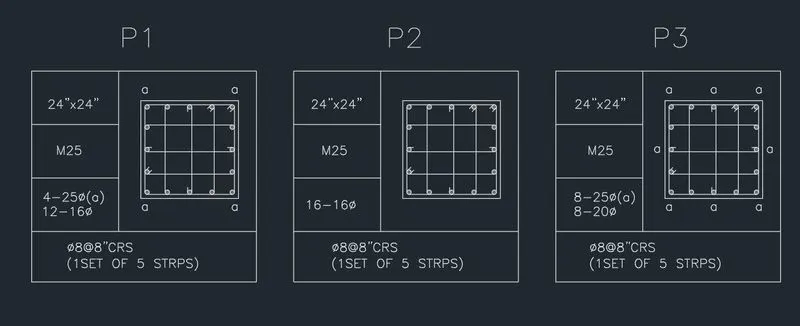
AIM: To sketch the column details using AutoCAD.
INTRODUCTION:
AutoCAD is a commercial computer-aided design (CAD) and drafting software application. Developed and marketed by Autodesk, AutoCAD was first released in December 1982 as a desktop app running on microcomputers with internal graphics controllers. Before AutoCAD was introduced, most commercial CAD programs ran on mainframe computers or minicomputers, with each CAD operator (user) working at a separate graphics terminal. AutoCAD is also available as mobile and web apps.
AutoCAD is used in industry, by architects, project managers, engineers, graphic designers, city planners and other professionals.
PROCEDURE:
Step 1: Open AutoCAD by clicking on the AutoCAD icon on the Desktop
Step 2: Start a new project by clicking Ctrl + N on the keyboard. A "Create new drawing" dialogue box will appear.
Step 3: Choose Advance option and select Engineering and precision to 0'0"
Step 4: Commands used are as follows:
- Type 'UN' in the command prompt and set the units to engineering and set the precision as per the data given and insertion scale as inches
- Type 'Limit' and specify lower unit as 0,0 and upper unit as 100',100'
- Type 'Zoom' and select All
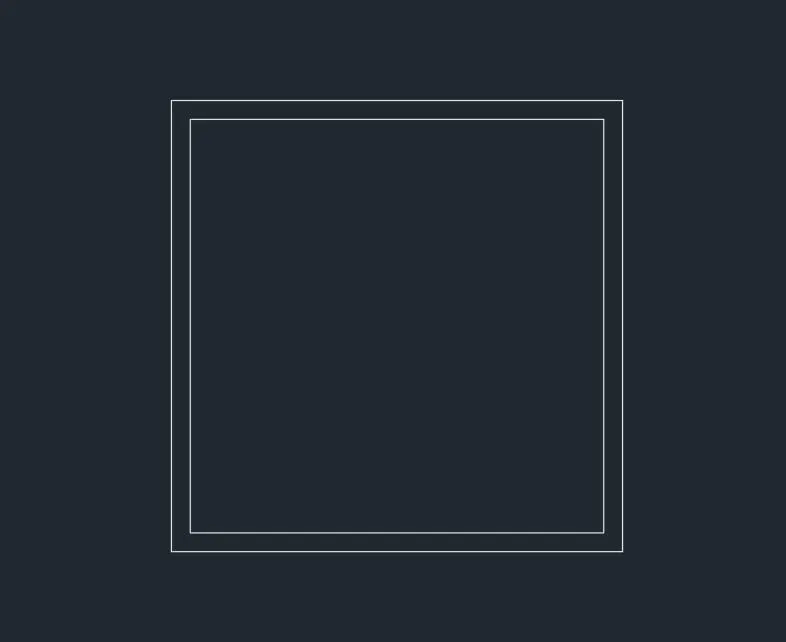
- Type 'L' for line tool and draw the 24" column
- Type 'C' to close the diagram
- Type 'O' for offset tool and offset the lines inward at a distance 1"
- Use Trim tool to trim off the unwanted lines
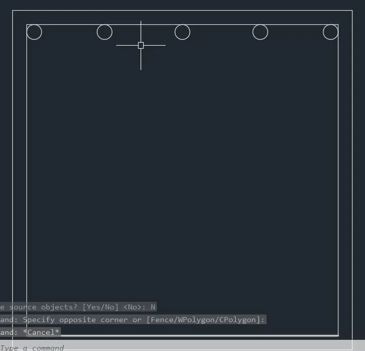
- Now using circle tool draw the section of the bars
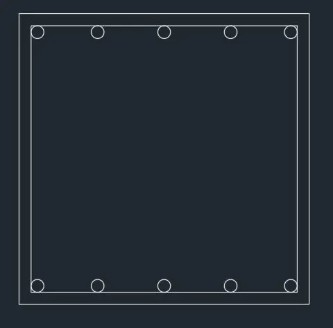
- Set the circle in equidistant from each other using copy tool
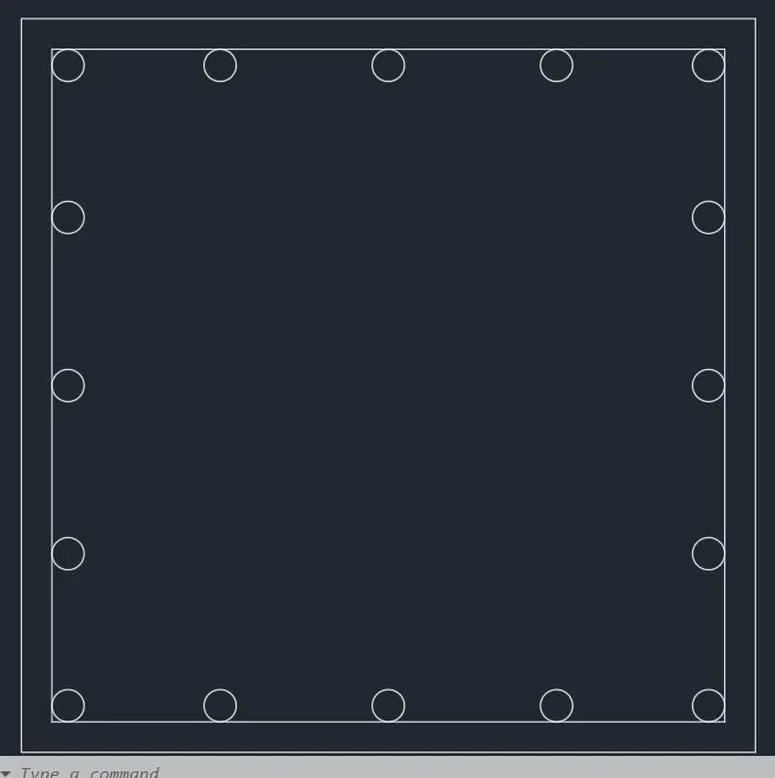
- Now using mirror tool mirror the circles drawn to the other sides
- Use trim tool to trim off the unwanted lines
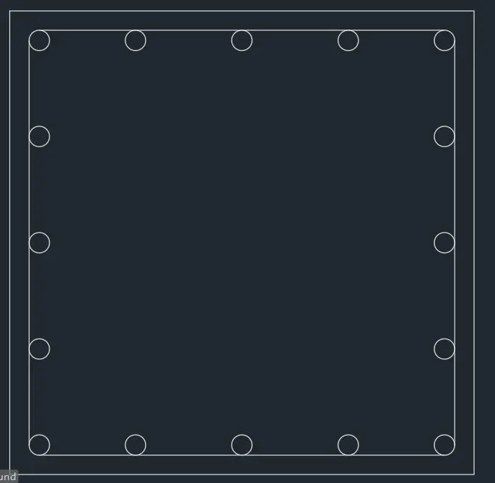
- Now Copy the lines using copy tool close to circle and take the base point as center of the circle and paste the lines in the x-direction
- Similarly do the same procedure in the y-direction
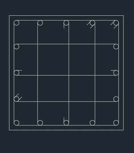
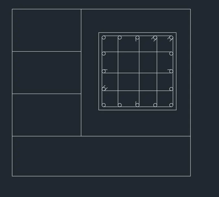
- Using Line tool and Rectangle tool draw the boxes to enclose the obove drawing and other details of the drawing
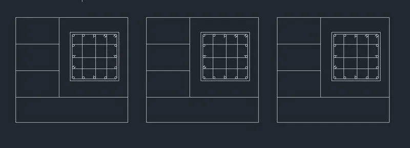
- Now using copy tool and selecting the multiple option make two more copies of the above drawn entire object
- Now Using mtext command write all the details in the boxes.
RESULT:
AIM: To draw the raft layout using AutoCAD.
INTRODUCTION:
AutoCAD is a commercial computer-aided design (CAD) and drafting software application. Developed and marketed by Autodesk, AutoCAD was first released in December 1982 as a desktop app running on microcomputers with internal graphics controllers. Before AutoCAD was introduced, most commercial CAD programs ran on mainframe computers or minicomputers, with each CAD operator (user) working at a separate graphics terminal. AutoCAD is also available as mobile and web apps.
AutoCAD is used in industry, by architects, project managers, engineers, graphic designers, city planners and other professionals.
PROCEDURE:
Step 1: Open AutoCAD by clicking on the AutoCAD icon on the Desktop
Step 2: Start a new project by clicking Ctrl + N on the keyboard. A "Create new drawing" dialogue box will appear.
Step 3: Choose Advance option and select Architectural and precision to 0'0 1/2"
Step 4: Commands used are as follows:
- Type 'UN' in the command prompt and set the units to architectural and set the precision as per the data given and insertion scale as inches
- Type 'Limit' and specify lower unit as 0,0 and upper unit as 100',100'
- Type 'Zoom' and select All
- Type 'L' and click anywhere in the screen
- Make sure the ortho mode is turned on
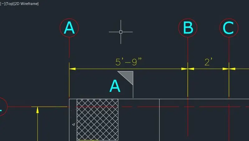
- draw vertical lines taking continuous distance 10'-`4 1/2`", 13'-`10 1/2`", 5'-9", 3',9", 5'-`7 1/2`", 5'-`10 1/2`", 4'-9", 3'-`7 1/2`", 5'-`7 1/2`"
- Draw horizontal lines taking continuous distance 5'-9", 2', 7', 4', 4'-6", 5'-`7 1/2`"
- Make sure the intersection mode is on in the object snap
- Now choose the next point as the intersection point of the first point and last point
- Close the diagram by clicking on the start point.
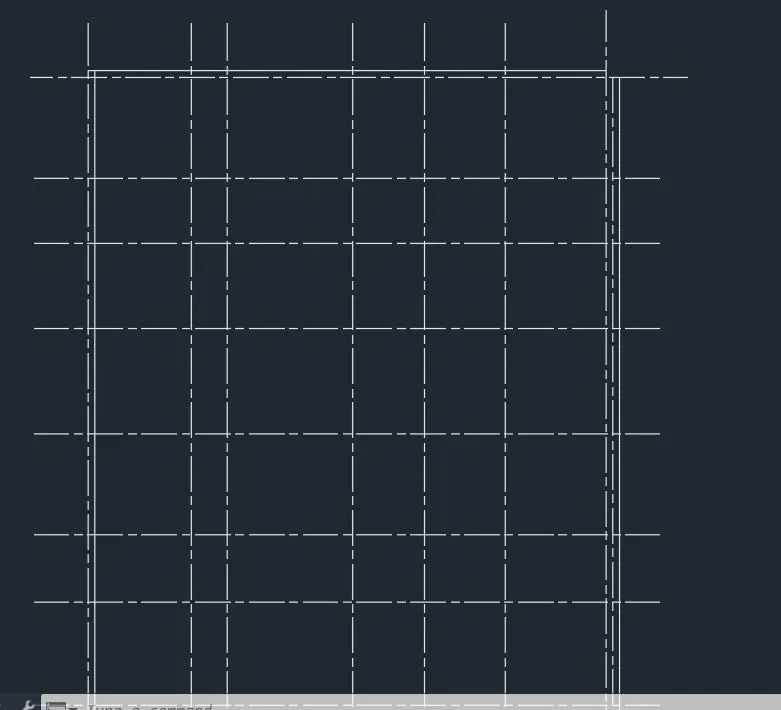
- Now type 'XL' for construction lines and draw contruction line intersecting the breaking points of the previously drawn lines
- Type 'O' for offset tool and offset the lines (which are the part of rectangular object ) outwards by taking offset distance as 3'
- Use Trim tool to trim off the unwanted lines
- Now load the line type from the ribbon bar as 'ACAD-ISO08W100'
- Select all the center lines and select the above line type
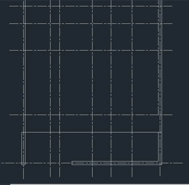
- The foundation dimension is 10'-`7 1/2`" x 8'. Draw this using line tool and offset tool
- With offset tool and offset distance at 3' and 2'-6" and line tool draw the column with size 24"x24" and 9"x30".
- The other foundation dimension is 6' x 6'-9". Draw this using line tool and offset tool
- Offset the foundation lines at 3' and trim off the unwanted lines
- Type 'Hatch' in the command prompt and Select Ansi137 from the ribbon bar
- Click on the areas of the column to hatch it.
- Select the hatched portions and right click and go to hatchedit and set the scale to 20
- Similarly hatch the bottom wall area with suitable hatch
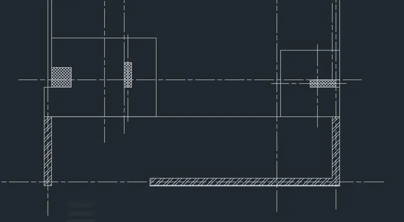
- Similarly using line tool and offset tool draw the other column details.
- Use hatch tool to hatch the portion
- Change the line type wherever necessary from the ribbon bar
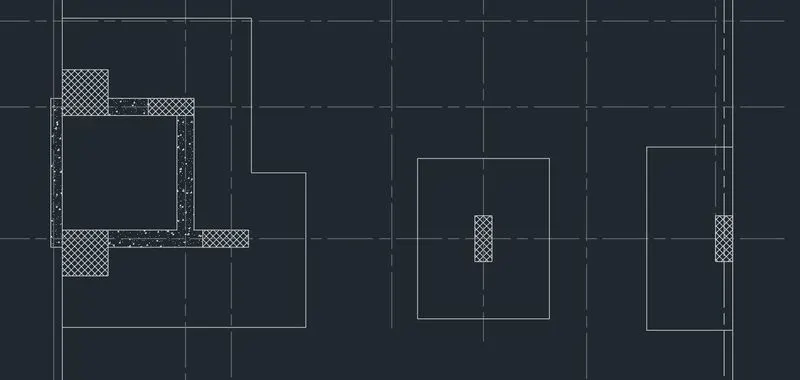
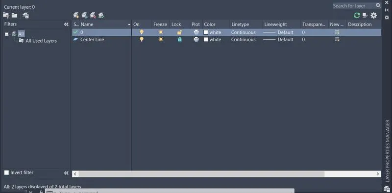
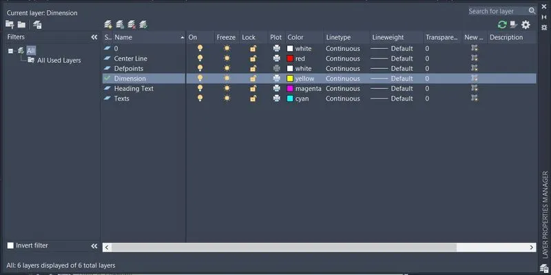
- For easy sketching create a layer and name it Center line.
- Now Select all the center lines which has a different linetype and assign it to the center line layer
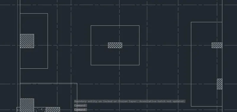
- Now go to layer properties and lock the center line layer
- With this it will be easy to sketch without getting disturbed by other lines
- Now using line tool and offset tool draw the other column details. We can also use rectangle tool for column and then offset it outward to create the foundation plan.
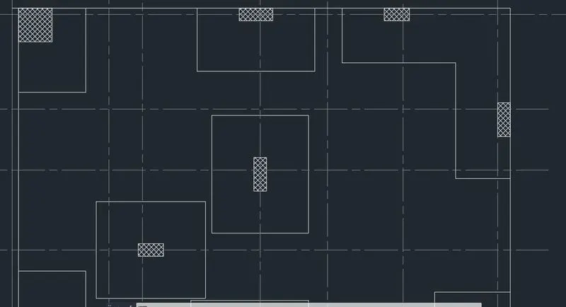
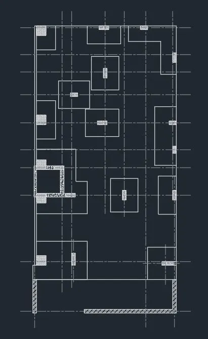
- Type ‘C’ for circle tool and draw a circle with random radius taken as 6.5”
- Select the circle and Type ‘M’ for move tool
- Select the base point as the intersection of the tangent and centerline in the x-direction
- Move the circle to the end point of the first horizontal center line at the top
- Now Copy the same moved circle and Type ‘M’ and select multiple option and paste the circle in the end points of the center line beneath
- Similarly do the same procedure for the vertical center lines
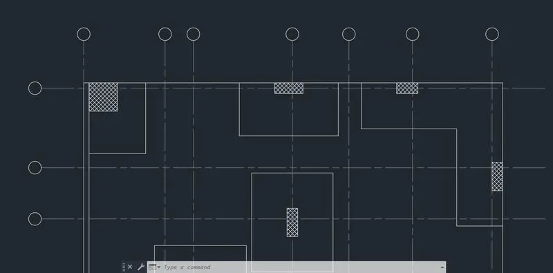
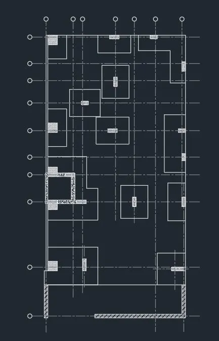
- Create a new layer naming Texts and set it to current
- Use mtext command to write the texts wherever necessary
- Scale the text using scaletext command
- Also Create a new layer naming dimensions and set it to current
- Use Dimlin command to dimension the drawing
- Type dimsty for modifying the dimensions line, arrows, texts and scale
- Also create a new layer naming Heading texts and assign the heading to this layer
- Assign different colours to the different layers for distinct visibility

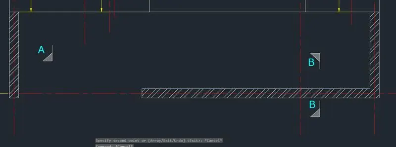
- Use Line tool to draw flag and its stick.
- Hatch the portion with Solid hatch and set the transparency to 60
- Using Copy tool make copies of it and paste it in the proper area of the drawing
- Copy the text A and B to the respective flags
- Use mirror tool to mirror the flags wherever necessary
RESULT:
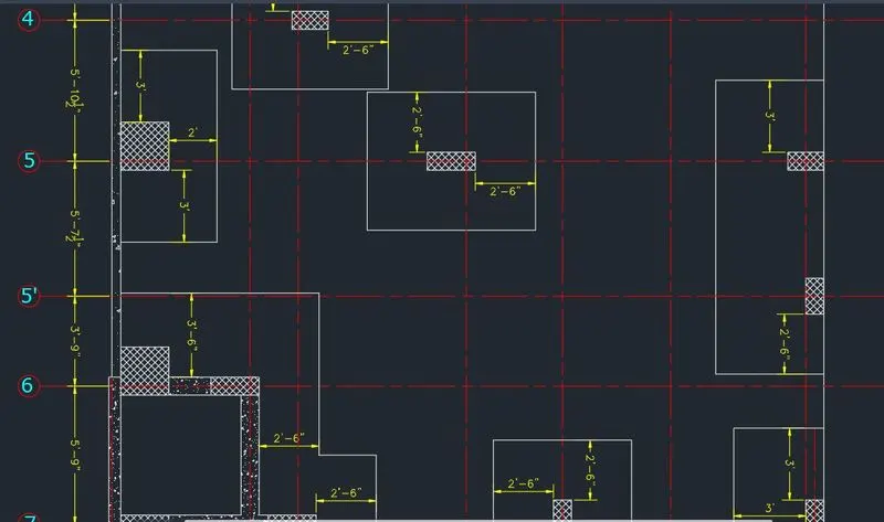
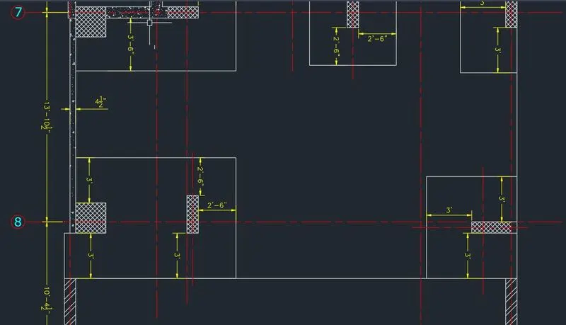
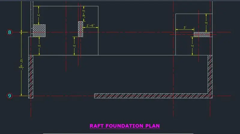
- The detailed procedure to draw the raft plan is shown above and the result is given below.