Creation of Column Schedule and Drawing Template using AutoCad
AIM: Creating a column schedule using AutoCAD.
INTRODUCTION:
AutoCAD is a commercial computer-aided design (CAD) and drafting software application. Developed and marketed by Autodesk, AutoCAD was first released in December 1982 as a desktop app running on microcomputers with internal graphics controllers. Before AutoCAD was introduced, most commercial CAD programs ran on mainframe computers or minicomputers, with each CAD operator (user) working at a separate graphics terminal. AutoCAD is also available as mobile and web apps.
AutoCAD is used in industry, by architects, project managers, engineers, graphic designers, city planners and other professionals.
PROCEDURE:
Step 1: Open AutoCAD by clicking on the AutoCAD icon on the Desktop
Step 2: Start a new project by clicking Ctrl + N on the keyboard. A "Create new drawing" dialogue box will appear.
Step 3: Choose Imperial Template
Step 4: Commands used are as follows:
- Type 'UN' in the command prompt and set the units to egineering and set the precision as per the data given.
- Type 'L' to invoke line tool and specify the first point anywhere in the screen
- Specify the second point as @ 30',0 (This value is assumed)
- Specify the next point as @ 0,10'
- Speficy the next point as @ -30',0
- Type 'c' to close the line
- Type 'O' to invoke offset tool and specify the offset as 2' and press enter
- Select the Top horizontal line and click on the bottom side of it
- Press ESC to Cancel the command
- Type 'O' to invoke offset tool and specify the offset as 1'-5" and press enter
- Select the Bottom horizontal line and click on the Top side of it
- Press ESC to Cancel the command
- Type 'O' to invoke offset tool and specify the offset as 2' and press enter
- Select the second Bottom horizontal line and click on the Top side of it
- Select the last offsetted line and click on the Top side of it
- Press ESC to Cancel the command
- Type 'O' to invoke offset tool and specify the offset as 2.5' and press enter
- Select the left vertical line and click on the right side of it
- Select the last offsetted line and click on the right side of it
- Select the last offsetted line and click on the right side of it
- Select the last offsetted line and click on the right side of it
- Select the last offsetted line and click on the right side of it
- Select the last offsetted line and click on the right side of it
- Select the last offsetted line and click on the right side of it
- Select the last offsetted line and click on the right side of it
- Select the last offsetted line and click on the right side of it
- Select the last offsetted line and click on the right side of it
- Select the last offsetted line and click on the right side of it
- Select the last offsetted line and click on the right side of it
- Press ESC to Cancel the command
- Type 'TR' to invoke Trim tool and trim off the unwanted lines
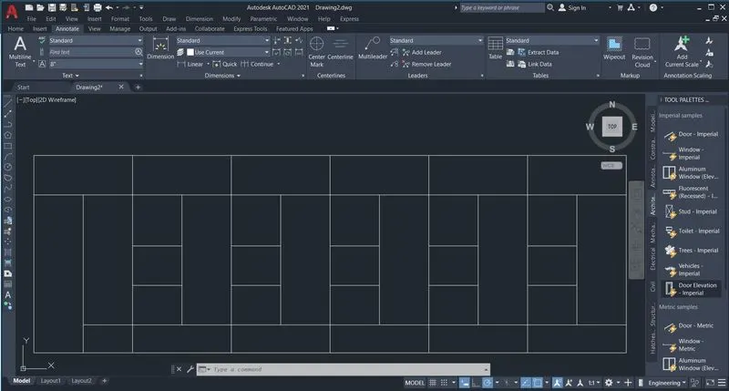
- Type 'mtext' to invoke multiline text tool
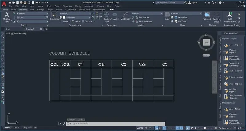
- Select the first point on top left side of the table and second point anywhere in the right side and type "Column Schedule"
- From the Ribbon bar and annotation panel choose underline option for the above texts
- Type 'dtext' to invoke single line text tool and specify first point first box of the table and specify text height as 8" and angle as 0
- Type the text 'COL. NOS.'
- Select Next box of the table and type the text 'C1'
- Similarly do the same prcedure for the other boxes in the first row of the table
- Now with Line tool and circle tool draw the column reinforcement details as per the dimensions given in the drawing
- Modify the line and circles with fillet tool, scale tool and mirror tool
- Use the 'Dtext' tool for the single line texts
- Also use the solid hatch for circles
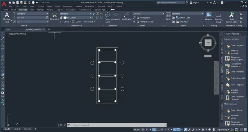
- Similarly do the same procedure for the other reinforcement details
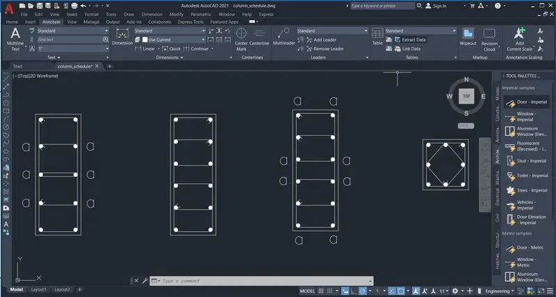
- Now select one entire reinforcement drawing and type 'M' for moving the object
- Select the base point anywhere in the drawing and move it to the corresponding box of the table
- Scale the drawing to fit in the box by using scale command
- Similarly do the same procedure for the reinforcement drawings
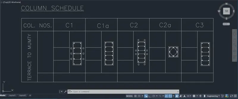
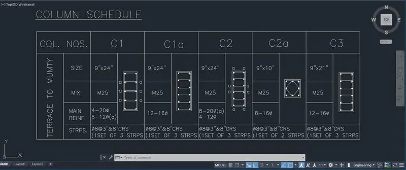
- Now Use 'Dtext' Command and fill all the boxed with the corresponding texts.
- Scale the texts to fit the boxes
- For main reinforcement detail and Stirrups boxes use 'mtext' commands (it is easier to install symbols using mtext command)
Step 5: Type command "save". A "Save drawing as" dialogue box will appear. Choose the directory and file name and click the save button.
RESULT:
AIM: Creating a window schedule using AutoCAD.
INTRODUCTION:
AutoCAD is a commercial computer-aided design (CAD) and drafting software application. Developed and marketed by Autodesk, AutoCAD was first released in December 1982 as a desktop app running on microcomputers with internal graphics controllers. Before AutoCAD was introduced, most commercial CAD programs ran on mainframe computers or minicomputers, with each CAD operator (user) working at a separate graphics terminal. AutoCAD is also available as mobile and web apps.
AutoCAD is used in industry, by architects, project managers, engineers, graphic designers, city planners and other professionals.
PROCEDURE:
Step 1: Open AutoCAD by clicking on the AutoCAD icon on the Desktop
Step 2: Start a new project by clicking Ctrl + N on the keyboard. A "Create new drawing" dialogue box will appear.
Step 3: Choose Imperial Template
Step 4: Commands used are as follows:
- Type 'UN' in the command prompt and set the units to architectural and set the precision as per the data given.
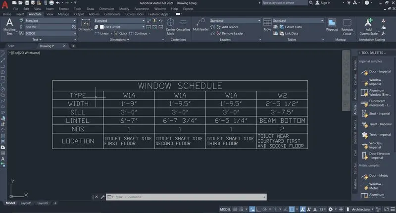
- Type 'Table' in the command prompt
- A INSERT TABLE dialogue box will appear
- Set the column as 5 and rows as 6 and click OK
- Click on the top box and type the title "WINDOW SCHEDULE" in the title box
- Similarly click on the header boxes and type the corresponding text data
- Similarly click on the data boxes and type the corresponding text data
- Allign the text data by left clicking on the box and choose the allignment option
- We can also change the text height by selecting the box and left clicking on it and selecting properties
- In the properties text height column is available from where we can change the text height
Step 5: Type command "save". A "Save drawing as" dialogue box will appear. Choose the directory and file name and click the save button.
RESULT:
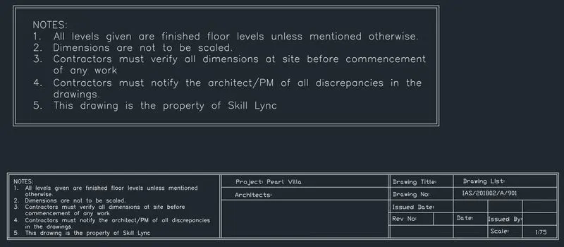
AIM: Creating a drawing template using AutoCAD.
INTRODUCTION:
AutoCAD is a commercial computer-aided design (CAD) and drafting software application. Developed and marketed by Autodesk, AutoCAD was first released in December 1982 as a desktop app running on microcomputers with internal graphics controllers. Before AutoCAD was introduced, most commercial CAD programs ran on mainframe computers or minicomputers, with each CAD operator (user) working at a separate graphics terminal. AutoCAD is also available as mobile and web apps.
AutoCAD is used in industry, by architects, project managers, engineers, graphic designers, city planners and other professionals.
PROCEDURE:
Step 1: Open AutoCAD by clicking on the AutoCAD icon on the Desktop
Step 2: Start a new project by clicking Ctrl + N on the keyboard. A "Create new drawing" dialogue box will appear.
Step 3: Choose Imperial Template
Step 4: Commands used are as follows:
- Type 'Rec' in the command prompt to invoke rectangle tool
- Select the first point anywhere in the screen
- Select the second point @20,5.5 and press enter
- Type 'O' in the command prompt to invoke offset tool
- Enter the offset as 0.1 and press enter
- Now select the Rectangle previoulsy drawn and offset it
- Type 'Rec' in the command prompt to invoke rectangle tool
- Select the first point anywhere in the screen but below the above drawn rectangle
- Select the second point @26,3 and press enter
- Type 'O' in the command prompt to invoke offset tool
- Enter the offset as 0.08 and press enter
- Now select the Rectangle previoulsy drawn and offset it
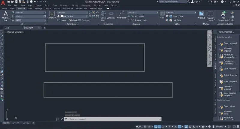
- Now Type 'L' for line tool and draw a line in left segment of the previously drawn circle (this is drawn just for reference)
- Type 'O' in the command prompt to invoke offset tool
- Enter the offset as 10 and press enter
- Now select the line previoulsy drawn and offset it in the right side of it
- Press ESC to cancel the command

- Type 'O' in the command prompt to invoke offset tool
- Enter the offset as 0.08 and press enter
- Now select the previoulsy offsetted line drawn and offset it in the right side of it
- Press ESC to cancel the command
- Type 'TR' for trim tool and trim off the unwanted lines
- Press ESC to cancel the command
- Type 'O' in the command prompt to invoke offset tool
- Enter the offset as 8 and press enter
- Now select the previoulsy offsetted line and offset it in the right side of it
- Press ESC to cancel the command
- Type 'O' in the command prompt to invoke offset tool
- Enter the offset as 0.08 and press enter
- Now select the previoulsy offsetted line and offset it in the right side of it
- Press ESC to cancel the command

- Type 'O' in the command prompt to invoke offset tool
- Enter the offset as 3 and press enter
- Now select the last line offsetted previously and offset it in the right side of it
- Press ESC to cancel the command
- Type 'DIV' to invoke divide tool
- Select the Second first line
- Give the value of number of segments as 5 and press enter
- Type 'L' for line tool and and draw line to the right side by taking first point as the first divided point (make sure the ortho mode is on)
- Similarly, continue the procedure and draw lines with Line tool for each division
- Press ESC to cancel the command
- Type 'TR' for trim tool and trim off the unwanted lines
- Press ESC to cancel the command
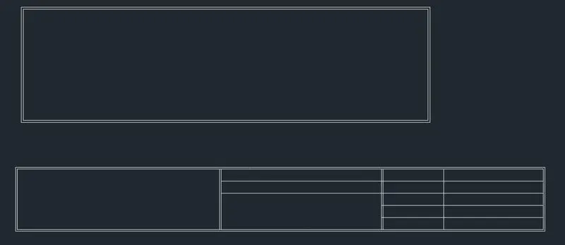
- Type 'DIV' to invoke divide tool
- Select the Second line from top of the bottom rectangle
- Give the value of number of segments as 3 and press enter
- Type 'L' for line tool and and draw line to the down side by taking first point as the first divided point (make sure the ortho mode is on)
- Similarly, continue the procedure and draw lines with Line tool for each division
- Press ESC to cancel the command
- Type 'TR' for trim tool and trim off the unwanted lines
- Press ESC to cancel the command
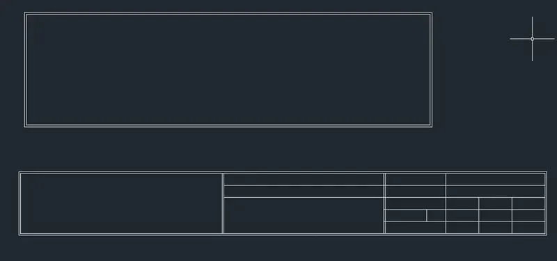
- Type 'mtext' for multiline text command and press enter
- Now define the text area in the upper drawn rectangle and type the given NOTES provided in the challenge
- To scale the text type 'Scaletext' in the command prompt to invoke scaletext tool
- We can use the grips to adjust the text area in the rectangular area
- Select all the texts and go to the ribbon bar and choose the font style as ROMAN
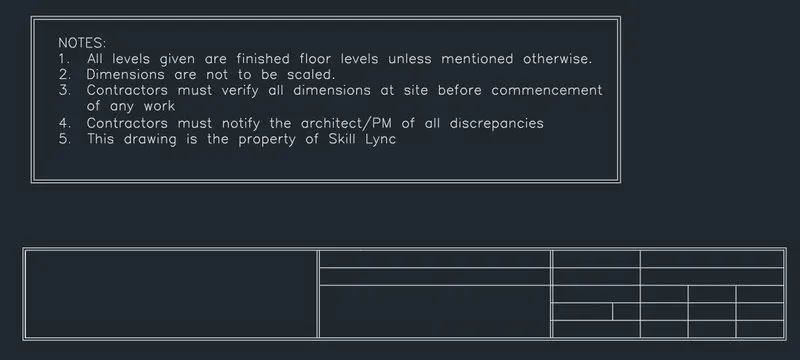
- Type 'mtext' for multiline text command and press enter
- Now define the text area in the lower drawn rectangle and type the given NOTES provided in the challenge
- To scale the text, type 'Scaletext' in the command prompt to invoke scaletext tool or go to the ribbon bar and change the scale
- We can use the grips to adjust the text area in the rectangular area
- Select all the texts and go to the ribbon bar and choose the font style as ROMAN or we can choose it beforehand
- Similarly fill all other boxes with the corresponding texts and adjust it by scaling it from the ribbon bar.
Step 5: Type command "save". A "Save drawing as" dialogue box will appear. Choose the directory and file name and click the save button.
RESULT:
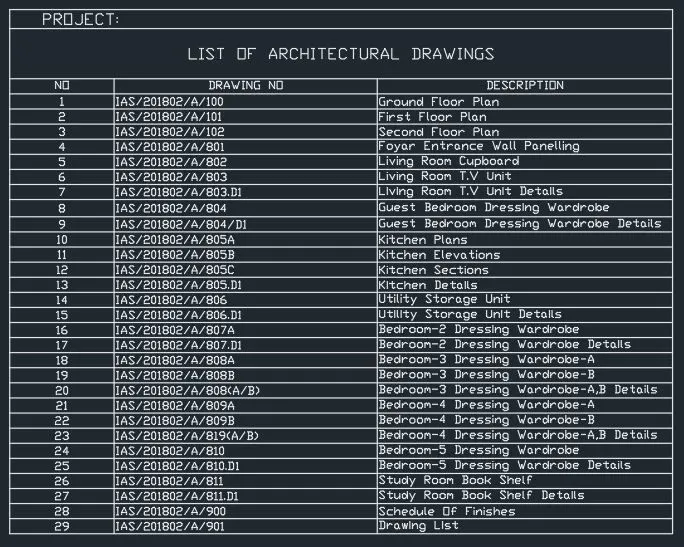
AIM: Creating list of drawing schedule using AutoCAD.
INTRODUCTION:
AutoCAD is a commercial computer-aided design (CAD) and drafting software application. Developed and marketed by Autodesk, AutoCAD was first released in December 1982 as a desktop app running on microcomputers with internal graphics controllers. Before AutoCAD was introduced, most commercial CAD programs ran on mainframe computers or minicomputers, with each CAD operator (user) working at a separate graphics terminal. AutoCAD is also available as mobile and web apps.
AutoCAD is used in industry, by architects, project managers, engineers, graphic designers, city planners and other professionals.
PROCEDURE:
Step 1: Open AutoCAD by clicking on the AutoCAD icon on the Desktop
Step 2: Start a new project by clicking Ctrl + N on the keyboard. A "Create new drawing" dialogue box will appear.
Step 3: Choose Imperial Template
Step 4: Commands used are as follows:
- Type 'Table' in the command prompt
- A INSERT TABLE dialogue box will appear
- Set the column as 3 and rows as 30 and click OK
- Click on the top box and type the title "PROJECT" in the title box
- Click on the next bottom box and type the "LIST OF ARCHITECTURAL DRAWINGS" in the title box
- Now type all the texts given in the challenge in the corresponding boxes
- Justify the 1st column of the Data as middle center from the ribbon bar
- Justify the 2nd and 3rd column data as middle left from the ribbon bar
Step 5: Type command "save". A "Save drawing as" dialogue box will appear. Choose the directory and file name and click the save button.
RESULT:
AIM: To create beam detail and provide text wherever given using AutoCAD.
INTRODUCTION:
AutoCAD is a commercial computer-aided design (CAD) and drafting software application. Developed and marketed by Autodesk, AutoCAD was first released in December 1982 as a desktop app running on microcomputers with internal graphics controllers. Before AutoCAD was introduced, most commercial CAD programs ran on mainframe computers or minicomputers, with each CAD operator (user) working at a separate graphics terminal. AutoCAD is also available as mobile and web apps.
AutoCAD is used in industry, by architects, project managers, engineers, graphic designers, city planners and other professionals.
PROCEDURE:
Step 1: Open AutoCAD by clicking on the AutoCAD icon on the Desktop
Step 2: Start a new project by clicking Ctrl + N on the keyboard. A "Create new drawing" dialogue box will appear.
Step 3: Choose Imperial Template
Step 4: Commands used are as follows:
- Type 'UN' and set the units to engineering and set the precision as 0'0"
- Type 'Limits' and set the limit o the space as 0',0' to 100',100'
- Type 'Zoom' and click 'A'
- Type 'L' for line tool and specify first point anywhere in the screen
- Specify second point as @0',4' (this value is assumed)
- Press ESC to cancel the command
- Type 'O' for offset tool and specify the offset value as 9"
- Select the Line created previously and click on the right side of it.
- Press ESC to cancel the command
- Type 'L' for line tool and join both the lines on both ends
- Press ESC to cancel the command
- Type 'L' for line tool and make jagged lines in the mid of both top and bottom horizontal line as shown in figure
- Press ESC to cancel the command
- Type 'TR' for trim tool and trim off the unwanted lines
- Type 'O' for offset tool and specify the offset value as 2'
- Select the bottom horizontal line and click on the top side of it
- Press ESC to cancel the command
- Type 'O' for offset tool and specify the offset value as 1'
- Select the previous offsetted line and click on the top side of it
- Press ESC to cancel the command
- Select the previous offsetted line and click on the right grip and stretch the line to the right side (make sure the ortho mode is on)
- Type 'O' for offset tool and specify the offset value as 9"
- Select the previous stretched line and click on the bottom side of it
- Press ESC to cancel the command
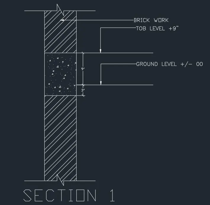
- Type 'hatch' and pick the internal point of the brick work area which is below the beam
- Select the hatch as Ansi132 from hatch creation in the ribbon bar
- Now go to hatch settings dialogue box by clicking on 'settings' from the command prompt area
- Now specify the scale as 6
- Click on the 'Close hatch creation' in the ribbon bar
- Similarly do the same procedure for the upper brickwork area
- Type 'hatch' and pick the internal point of the beam area
- Select the hatch as AR-Conc from hatch creation in the ribbon bar
- Now go to hatch settings dialogue box by clicking on 'settings' from the command prompt area
- Now specify the scale as 0.5
- Click on the 'Close hatch creation' in the ribbon bar
- Type 'mtext' and choose the bottom area of the drawing and type 'SECTION 1"
- Type 'dimsty' and adjust the unit and precision and scale of the dimesions
- Type 'dimlin' and provide the dimesions as given in the figure
- Click on multileader option in the annotaion panel which is in the ribbon bar and Specify the description as shown in the figure
Step 5: Type command "save". A "Save drawing as" dialogue box will appear. Choose the directory and file name and click the save button.
RESULT: