Creating a Residence Layout, Seating plan, Toilet and Utility room plan using AutoCad
AIM: Creating the residence plan using AutoCAD.
INTRODUCTION:
AutoCAD is a commercial computer-aided design (CAD) and drafting software application. Developed and marketed by Autodesk, AutoCAD was first released in December 1982 as a desktop app running on microcomputers with internal graphics controllers. Before AutoCAD was introduced, most commercial CAD programs ran on mainframe computers or minicomputers, with each CAD operator (user) working at a separate graphics terminal. AutoCAD is also available as mobile and web apps.
AutoCAD is used in industry, by architects, project managers, engineers, graphic designers, city planners and other professionals.
PROCEDURE:
Step 1: Open AutoCAD by clicking on the AutoCAD icon on the Desktop
Step 2: Start a new project by clicking Ctrl + N on the keyboard. A "Create new drawing" dialogue box will appear.
Step 3: Choose Imperial Template
Step 4: Commands used are as follows:
- Type 'un' in the command prompt for units dialogue box and set the units to engineering and set the precision as per the drawing
- Type 'Limmax' and specify the max limit of the space as 100',100'
- Type 'Zoom' and select all
- Type 'XL' for construction lines and choose vertical and click anywhere in the screen
- Press Esc to cancel the command
- Type 'XL' for construction lines and choose horizontal and click anywhere in the screen
- Press Esc to cancel the command
- Type 'O' for offset tool and specify the offset as 9"
- Select the Vertical construction line and click on the right side of it
- Press Esc to cancel the command
- Similarly do the offsetting for the horzontal line by taking 9" as the offset value.
- Press Esc to cancel the command
- Type 'O' for offset tool and specify the offset as 6'
- Select the horizontal construction line and click on the top side of it
- Press Esc to cancel the command
- Type 'O' for offset tool and specify the offset as 9"
- Select the last horizontal construction line and click on the top side of it
- Press Esc to cancel the command
- Type 'O' for offset tool and specify the offset as 12' 6"
- Select the first vertical construction line and click on the right side of it
- Press Esc to cancel the command
- Type 'O' for offset tool and specify the offset as 9"
- Select the vertical line offsetted previously and click on the left side of it
- Press Esc to cancel the command
- Type 'O' for offset tool and specify the offset as 6' 8"
- Select the last horzontal construction line and click on the top side of it
- Press Esc to cancel the command
- Type 'O' for offset tool and specify the offset as 4.5"
- Select the last horzontal construction line and click on the top side of it
- Press Esc to cancel the command
- Type 'O' for offset tool and specify the offset as 6' 4"
- Select the last vertical construction line drawn and click on the left side of it
- Press Esc to cancel the command
- Type 'TR' for Trim tool and with fence mode trim off the unwanted lines (we can also use Fillet tool and take radius as 0 to meet up the lines)
- Press Esc to cancel the command
- Type 'O' for offset tool and specify the offset as 25'
- Select the first vertical construction line drawn and click on the right side of it
- Press Esc to cancel the command
- Type 'O' for offset tool and specify the offset as 9"
- Select the vertical construction line offsetted and click on the left side of it
- Press Esc to cancel the command
- Type 'EX' for extend tool and select the bottom horizontal line to meet the last vertical line
- Type 'O' for offset tool and specify the offset as 43' 6.5"
- Select the bottom horizontal line and click on the top side of it
- Press Esc to cancel the command
- Type 'O' for offset tool and specify the offset as 9"
- Select the horizontal line previously drawn and click on the bottom side of it
- Press Esc to cancel the command
- Type 'TR' for Trim tool and with fence mode trim off the unwanted lines (we can also use Fillet tool and take radius as 0 to meet up the lines)
- Press Esc to cancel the command
- Type 'O' for offset tool and specify the offset as 13' 9.5"
- Select the bottom horizontal line and click on the top side of it
- Press Esc to cancel the command
- Type 'O' for offset tool and specify the offset as 9"
- Select the horizontal line previously drawn and click on the top side of it
- Press Esc to cancel the command
- Type 'O' for offset tool and specify the offset as 3' 3"
- Offset the Door D3 by selecting the middle vertical line
- Press Esc to cancel the command
- Type 'O' for offset tool and specify the offset as 1' 3"
- Select the vertical line offsetted previously and click on the right side of it
- Press Esc to cancel the command
- Type 'O' for offset tool and specify the offset as 6'
- Select the vertical line offsetted previously and click on the right side of it
- Press Esc to cancel the command
- Make sure the midpoint is marked in the object snap status bar
- Type 'L' for line tool and select first point as the mid point of the previously drawn vertical line and select the second point as the mid point of the second vertical line previously drawn
- Press Esc to cancel the command
- Type 'TR' for Trim tool and with fence mode trim off the unwanted lines (we can also use Fillet tool and take radius as 0 to meet up the lines)
- Press Esc to cancel the command
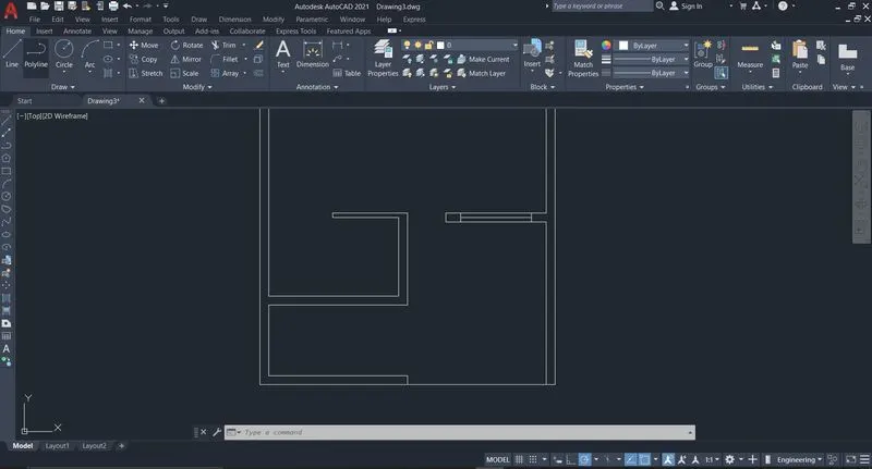
- Type 'O' for offset tool and specify the offset as 18' 0.5"
- Select the bottom second wall line and click on the top side of it
- Press Esc to cancel the command
- Type 'EX' for extend tool and select the line previously drawn to meet the vertical line
- Type 'O' for offset tool and specify the offset as 4.5"
- Select the extended line and click on the top side of it
- Press Esc to cancel the command
- Type 'O' for offset tool and specify the offset as 4' 6"
- Select the last offsetted line and click on the top side of it
- Press Esc to cancel the command
- Type 'O' for offset tool and specify the offset as 4.5"
- Select the last offsetted line and click on the top side of it
- Press Esc to cancel the command
- Type 'O' for offset tool and specify the offset as 8' 3"
- Select the nearest left vertical line and click on the right side of it
- Press Esc to cancel the command
- Type 'O' for offset tool and specify the offset as 4.5"
- Select the last offsetted line and click on the right side of it
- Press Esc to cancel the command
- Type 'O' for offset tool and specify the offset as 8' 1.5"
- Select the nearest right vertical line and click on the left side of it
- Press Esc to cancel the command
- Type 'O' for offset tool and specify the offset as 4.5"
- Select the last offsetted line and click on the left side of it
- Press Esc to cancel the command
- Type 'O' for offset tool and specify the offset as 2' 6"
- And offset the Door D2 for both the Toilet plans
- Press Esc to cancel the command
- Type 'TR' for Trim tool and with fence mode trim off the unwanted lines (we can also use Fillet tool and take radius as 0 to meet up the lines)
- Press Esc to cancel the command
- Type 'O' for offset tool and specify the offset as 11' 7.5"
- Select the nearest left vertical line and click on the right side of it
- Press Esc to cancel the command
- Type 'O' for offset tool and specify the offset as 4.5"
- Select the last offsetted line and click on the right side of it
- Press Esc to cancel the command
- Type 'TR' for Trim tool and with fence mode trim off the unwanted lines (we can also use Fillet tool and take radius as 0 to meet up the lines)
- Press Esc to cancel the command
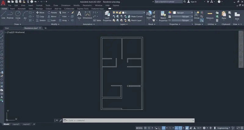
- For Doors we can draw it by line and circle or arc tool
- Type 'L' for Line tool specify the hinged end point of the door as first point draw a horizontal line with distance 0.5"
- Now through polor tracking on, specify the next point as 3' 3" for D3 in 90 degree direction
- Press esc to cancel the command
- Type 'Arc' for arc tool and select center option from the command prompt (we can opt it from draw panel aslo)
- Specify the center by selecting the hinged portion of the door
- Specify first point as the intersection of the apparent hinged line and the end point of the door opening
- Specify second point as the end point of the door line which was previously drawn at 90 degree
- If the line and the arc does not meet then use the Fillet tool at radius 0 to make them meet.
- Similarly follow the above procedure for D1 and D2 doors
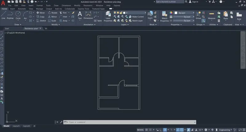
- Type 'EX' for extend tool
- Select the middle bottom vertical line which is on the left side and extend it to the bottom vertical line
- Type 'TR' for Trim tool and with fence mode trim off the unwanted lines (we can also use Fillet tool and take radius as 0 to meet up the lines)
- Press Esc to cancel the command
- Type 'O' for offset tool and specify the offset as 1'
- Select the extended line and click on the left side of it (make sure to choose multiple optionn)
- Repeat the above procedure 8 times for stairs
- Press Esc to cancel the command
- Type 'O' for offset tool and specify the offset as 3'
- Select the second bottom horizontal line and click on the top side of it
- Press Esc to cancel the command
- Type 'TR' for Trim tool and with fence mode trim off the unwanted lines (we can also use Fillet tool and take radius as 0 to meet up the lines)
- Now with the Line tool join the corner points with the trimmed line
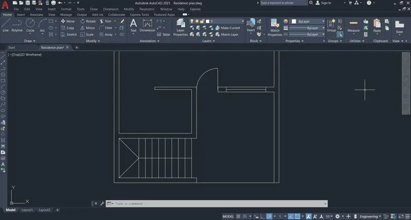
- Type 'O' for offset tool and specify the offset as 2'
- Select the bottom horizontal line of the kitchen area and click on the top side of it
- Similarly select right side vertical line of the kitchen area and click left side of it
- Press Esc to cancel the command
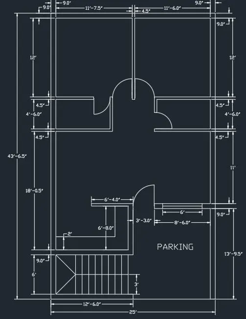
- Type 'dimlin' for linear dimension tool and give dimesions to every lines (adjust the scale from 'scaletext' command)
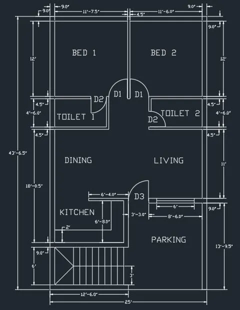
- Type 'mtext' command for text tool and mention the drawing areas. ( we can also find this tool in the ribbon annotation)
- Now go to the ribbon and select layer properties
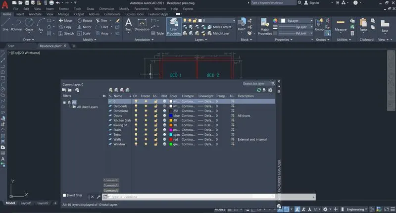
- Now select new layer and create layers such as wall, door, window, stairs, railing of stair, dimesions, kitchen slab and texts
- Specify colour of each layers as shown below
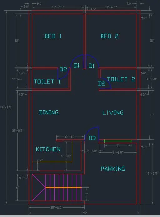
- Now assign objects of the drawing to the corresponding layers by selecting the object and selecting the layer
- We can also change the lineweight of the staris railing by clicking the layer properties and selecting the line weight of the railing staris and then selecting the desired line weight
- To make lineweight visible type 'LW' command and mark the 'display lineweight'
Step 5: Type command "save". A "Save drawing as" dialogue box will appear. Choose the directory and file name and click the save button.
RESULT:
AIM: Creating the outdoor seating with canopy using AutoCAD.
INTRODUCTION:
AutoCAD is a commercial computer-aided design (CAD) and drafting software application. Developed and marketed by Autodesk, AutoCAD was first released in December 1982 as a desktop app running on microcomputers with internal graphics controllers. Before AutoCAD was introduced, most commercial CAD programs ran on mainframe computers or minicomputers, with each CAD operator (user) working at a separate graphics terminal. AutoCAD is also available as mobile and web apps.
AutoCAD is used in industry, by architects, project managers, engineers, graphic designers, city planners and other professionals.
PROCEDURE:
Step 1: Open AutoCAD by clicking on the AutoCAD icon on the Desktop
Step 2: Start a new project by clicking Ctrl + N on the keyboard. A "Create new drawing" dialogue box will appear.
Step 3: Choose Metric
Step 4: Commands used are as follows:
- Type 'un' in the command prompt for units dialogue box and set the units to decimal and set the precision as per the drawing and set insertion scale as millimeter
- Type 'Limmax' and specify the max limit of the space as 10000,10000
- Type 'Zoom' and select all
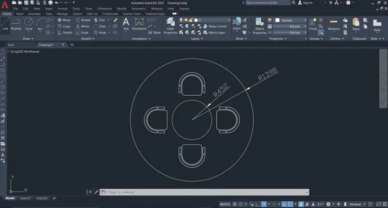
- Type 'C' for circle tool and draw a circle of R226 (assumed for seating)
- Type 'XL' for construction lines and choose vertical and click the center point of the circle (make sure the center is marked in the object snap)
- Press Esc to cancel the command
- Type 'TR' for trim tool and trim the right semi circle
- Press Esc to cancel the command
- Type 'O' for offset tool and specify the offset value as 20
- Now select the semi circle and click on the left side
- Press Esc to cancel the command
- Type 'O' for offset tool and specify the offset value as 50
- Now select the offsetted semi circle and click on the left side
- Press Esc to cancel the command
- Type 'L' for line tool and click on the end point of the first drawn semi circle as first point
- Make sure the polar tracking is on and marked at 90 degree
- Through polar tracking specify the next point at 226 at an angle 0 degree
- Similarly draw a line of distance 226 from the other end of the semi circle by Line tool
- Now with the line tool join the both lines
- Type 'F' for fillet tool and select radius and specify radius as 60
- Select the joined line previously drawn to fillet
- Type 'O' for offset tool and specify the offset value as 20
- Now select the upper horizontal line and click on the top side
- Now select the lower horizontal line and click on the down side
- Press Esc to cancel the command
- Type 'O' for offset tool and specify the offset value as 50
- Now select the offsetted upper horizontal line and click on the top side
- Now select the offsetted lower horizontal line and click on the down side
- Press Esc to cancel the command
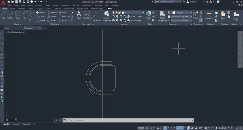
- Type 'O' for offset tool and specify the offset value as 20
- Now select the vertical construction line and click on the right side
- Type 'L' for line tool and join the extreme right horizontal lines which are open
- Press Esc to cancel the command
- Type 'TR' for Trim tool and with fence mode trim off the unwanted lines
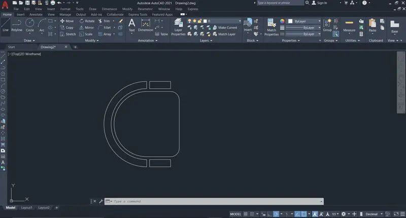
- Type 'C' for circle tool and click anywhere in the screen to specify the center (it is convinient to click nearby the above drawn object)
- Now specify the radius as R1398 and then press enter
- Make sure the center is market in the object snap
- Type 'C' for circle tool and select the center point of the above drawn circle to specify the center
- Now specify the radius as R452 and then press enter
- Type 'M' for Move tool and select the previously drawn seating and press enter
- Now select the base point of the seating and place the object in the mid of concetric curves of the circle taking the reference line as the center of the circles drawn having radius R1398 and R452
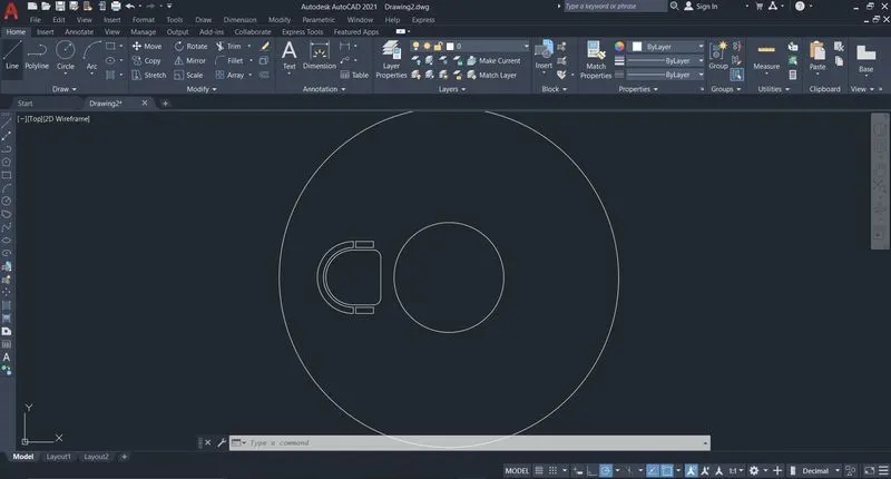
- Type 'MI' for mirror tool and select the seating object and press enter
- Now specify the first point as the center of the concentric circles and click on it (make sure the ortho is on in the status bar, it helps to define the mirror line)
- Select 'No' if asked to erase the source
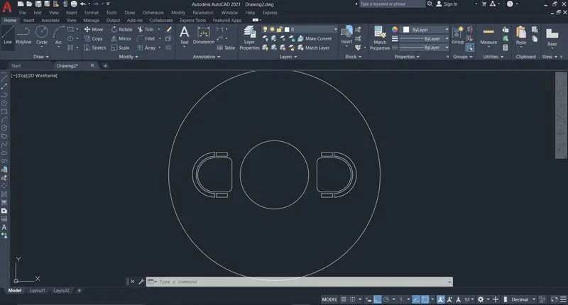
- Type 'MI' for mirror tool and select the both seating object and press enter
- Now specify the first point as the center of the concentric circles and click on it (make sure the polar tracking in set to 45 degree)
- Now mirror the object at 45 degree
- Select 'No' if asked to erase the source
Step 5: Type command "save". A "Save drawing as" dialogue box will appear. Choose the directory and file name and click the save button.
RESULT:
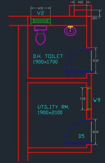
AIM: Creating the part plan for toilet and utilities room using AutoCAD.
INTRODUCTION:
AutoCAD is a commercial computer-aided design (CAD) and drafting software application. Developed and marketed by Autodesk, AutoCAD was first released in December 1982 as a desktop app running on microcomputers with internal graphics controllers. Before AutoCAD was introduced, most commercial CAD programs ran on mainframe computers or minicomputers, with each CAD operator (user) working at a separate graphics terminal. AutoCAD is also available as mobile and web apps.
AutoCAD is used in industry, by architects, project managers, engineers, graphic designers, city planners and other professionals.
PROCEDURE:
Step 1: Open AutoCAD by clicking on the AutoCAD icon on the Desktop
Step 2: Start a new project by clicking Ctrl + N on the keyboard. A "Create new drawing" dialogue box will appear.
Step 3: Choose Metric
Step 4: Commands used are as follows:
- Type 'un' in the command prompt for units dialogue box and set the units to decimal and set the precision as per the drawing and set insertion scale as millimeter
- Type 'Limmax' and specify the max limit of the space as 10000,10000
- Type 'Zoom' and select all
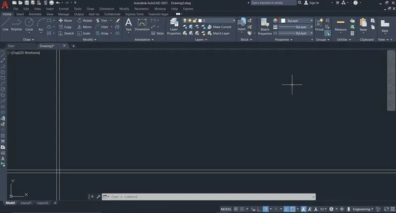
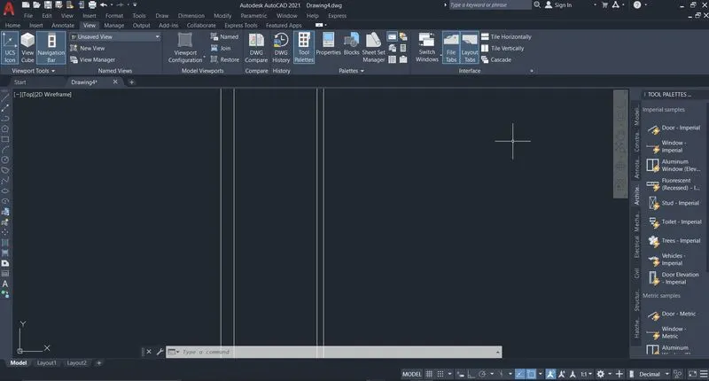
- Type 'XL' for construction line tool in the command prompt and select vertical option
- Click anywhere in the screen
- Press ESC to cancel the command
- Type 'O' for offset tool and specify the offset as 300
- Select the vertical construction line and click on the right side of it
- Press ESC to cancel the command
- Type 'O' for offset tool and specify the offset as 1900
- Select the last vertical construction line offsetted and click on the right side of it
- Press ESC to cancel the command
- Type 'O' for offset tool and specify the offset as 150
- Select the last vertical construction line offsetted and click on the right side of it
- Press ESC to cancel the command
- Type 'XL' for construction line tool in the command prompt and select horizontal option
- Click anywhere in the screen
- Press ESC to cancel the command
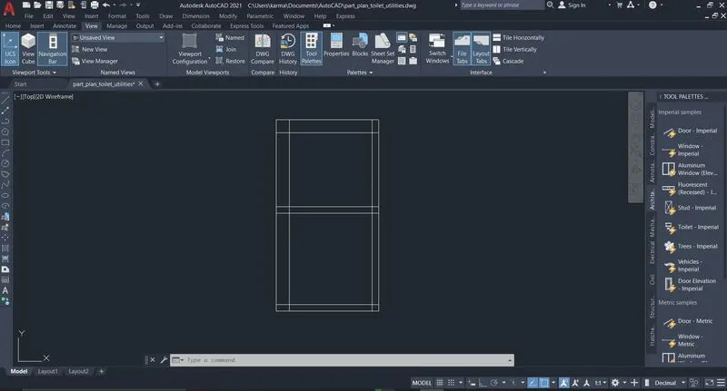
- Type 'O' for offset tool and specify the offset as 150
- Select the horizontal construction line and click on the top side of it
- Press ESC to cancel the command
- Type 'O' for offset tool and specify the offset as 2100
- Select the last horizontal construction line offsetted and click on the top side of it
- Press ESC to cancel the command
- Type 'O' for offset tool and specify the offset as 150
- Select the last horizontal construction line offsetted and click on the top side of it
- Press ESC to cancel the command
- Type 'O' for offset tool and specify the offset as 1700
- Select the last horizontal construction line offsetted and click on the top side of it
- Press ESC to cancel the command
- Type 'O' for offset tool and specify the offset as 300
- Select the last horizontal construction line offsetted and click on the top side of it
- Press ESC to cancel the command
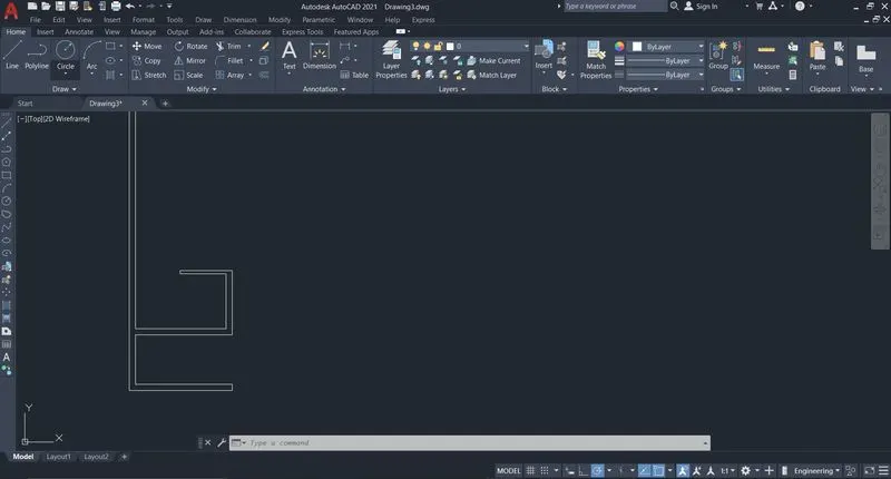
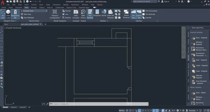
- Type 'TR' for Trim tool and with fence mode trim off the unwanted lines
- Press ESC to cancel the command
- Type 'O' for offset tool and specify the offset as 100
- Select the bottom second horizontal line and click on the top side of it
- Press ESC to cancel the command
- Type 'O' for offset tool and specify the offset as 828
- Select the last horizontal line offsetted and click on the top side of it
- Press ESC to cancel the command
- Type 'O' for offset tool and specify the offset as 150
- Select the mid lower horizontal line and click on the down side of it
- Press ESC to cancel the command
- Type 'O' for offset tool and specify the offset as 728
- Select the last horizontal line offsetted and click on the down side of it
- Press ESC to cancel the command
- Type 'O' for offset tool and specify the offset as 150
- Select the mid upper horizontal line and click on the top side of it
- Press ESC to cancel the command
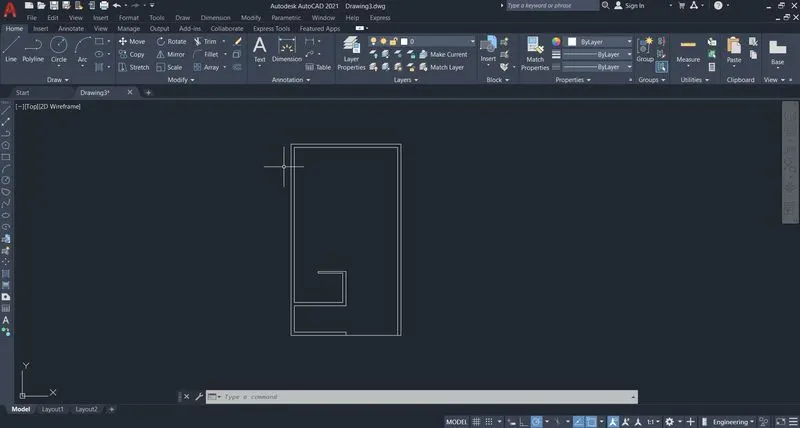
- Type 'TR' for Trim tool and with fence mode trim off the unwanted lines
- Press ESC to cancel the command
- Type 'L' for line tool and draw the door and window hinges with random dimensions
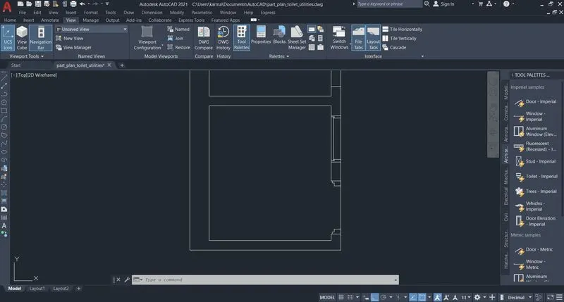
- Type 'O' for offset tool and specify the offset as 832
- Select the mid T-section upper horizontal line and click on the top side of it
- Press ESC to cancel the command
- Type 'O' for offset tool and specify the offset as 201
- Select the top-most horizontal line and click on the top side of it
- Press ESC to cancel the command
- Type 'O' for offset tool and specify the offset as 150
- Select the last horizontal line offsetted and click on the top side of it
- Press ESC to cancel the command
- Type 'EX' for extend tool and select the right wall line to extend it to the top previously offsetted lines
- Press ESC to cancel the command
- Type 'O' for offset tool and specify the offset as 402
- Select the previously extended line and click on the left side of it
- Press ESC to cancel the command
- Type 'O' for offset tool and specify the offset as 150
- Select the last vertical line offsetted and click on the left side of it
- Press ESC to cancel the command
- Type 'TR' for Trim tool and with fence mode trim off the unwanted lines
- Press ESC to cancel the command
- Type 'O' for offset tool and specify the offset as 100
- Select the left second vertical line and click on the right side of it
- Press ESC to cancel the command
- Type 'O' for offset tool and specify the offset as 631
- Select the last vertical line offsetted and click on the right side of it
- Press ESC to cancel the command
- Type 'TR' for Trim tool and with fence mode trim off the unwanted lines
- Press ESC to cancel the command
- Now Type 'L' for line tool and draw the door hinges and ventilator of toilet by taking random dimensions (or we can copy the previously drawn hinges and set it on the Toilet door by command 'CO')
- Press ESC to cancel the command
- Type 'TR' for Trim tool and with fence mode trim off the unwanted lines
- Press ESC to cancel the command
- For Doors we can draw it by line and circle or arc tool
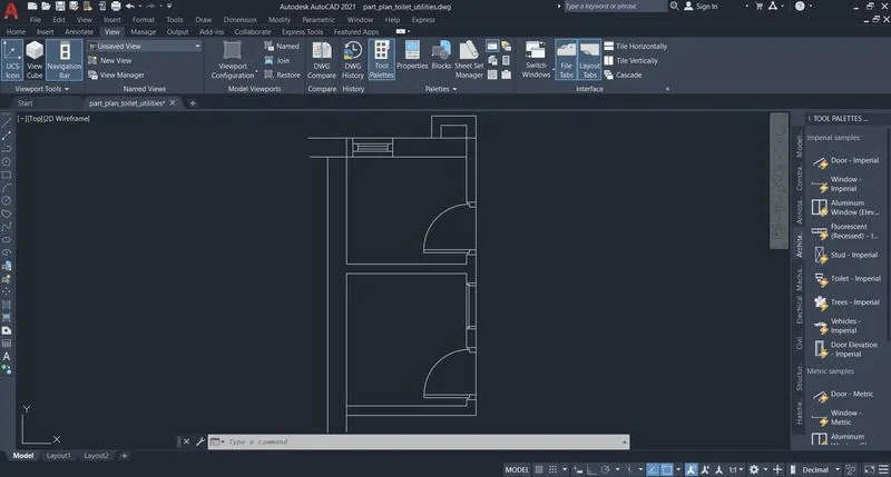
- Type 'L' for line tool and draw the door by taking first point as the hinge of the door
- Press esc to cancel the command
- Type 'Arc' for arc tool and select center option from the command prompt (we can opt it from draw panel aslo)
- Specify the center by selecting the first hinged portion of the door
- Specify first point as the other hinged portion of the door
- Specify second point randomly and make the door and the arc meet at a point
- Type 'TR' for Trim tool and with fence mode trim off the unwanted lines and curves
- Press ESC to cancel the command
- Similarly follow the above procedure for the Toilet door
- Now to insert the toilet seating and wash basin either type 'ADC" in the command prompt or insert it from View menu in the ribbon bar and then select tool pallets.
- Type 'mtext' command for text tool and mention the drawing areas. ( we can also find this tool in the ribbon annotation)
- Type 'dimlin' for linear dimension tool and give dimesions to every lines (adjust the scale from 'scaletext' command)
- Now go to the layer properties and create new layers as given below. Also choose the line weight of the wall as 0.30mm
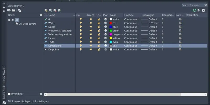
- Now assign the objects to the respected layers by selecting the objects and than selecting the corresponding layer from the ribbon bar
- To display the line weight type 'LW' command and mark the display lineweight from the dialogue box
Step 5: Type command "save". A "Save drawing as" dialogue box will appear. Choose the directory and file name and click the save button.
RESULT: