Creating Bar Bending schedule, Different Door types, and Creation of standard drawing templates using AutoCad
AIM: To create the door types for warehouse and creating blocks for the respective doors using AutoCad.
INTRODUCTION:
- AutoCAD is a commercial computer-aided design (CAD) and drafting software application. Developed and marketed by Autodesk, AutoCAD was first released in December 1982 as a desktop app running on microcomputers with internal graphics controllers. Before AutoCAD was introduced, most commercial CAD programs ran on mainframe computers or minicomputers, with each CAD operator (user) working at a separate graphics terminal. AutoCAD is also available as mobile and web apps.
- AutoCAD is used in industry, by architects, project managers, engineers, graphic designers, city planners and other professionals.
PROCEDURE:
Step 1: Open AutoCAD by clicking on the AutoCAD icon on the Desktop.
Step 2: Start a new project by clicking Ctrl + N on the keyboard. A "Create new drawing" dialogue box will appear.
Step 3: Choose metric option and click OK.
Step 4: Commands used are as follows.
- Type 'UN' in the command prompt and set the units to decimal and set the precision as per the data given and insertion scale as millimeter.
- Type 'Limit' and specify lower unit as 0,0 and upper unit as 10000,10000.
- Type 'Zoom' and select All.
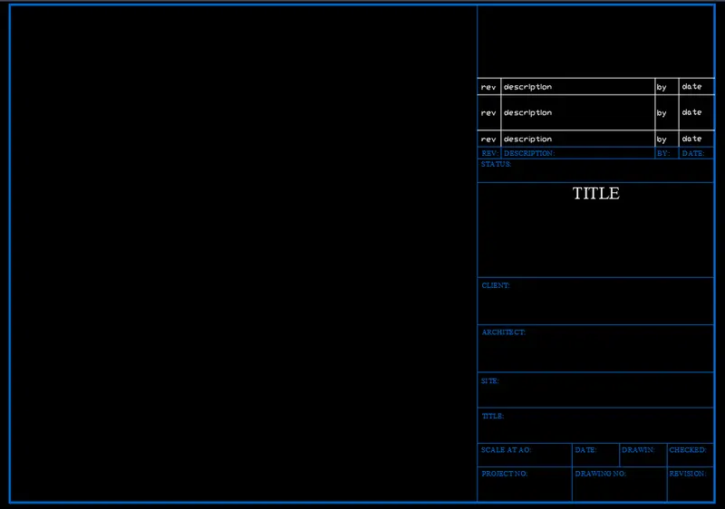
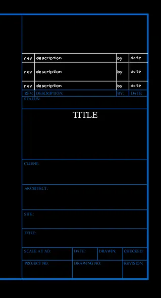
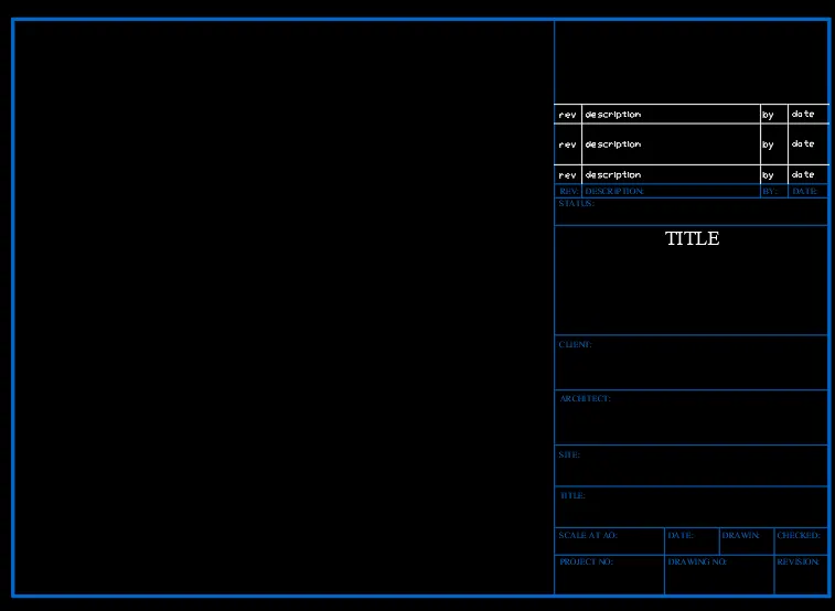
PART A: Creating Custom1_titleblock:
- Type 'Rec' and click in the screen to specify first point.
- Type @297,210.
- Select the rectangle and type 'x' to explode.
- Type 'O' and specify the offset distance as 100.
- Select the right vertical line and offset it inward.

- Similarly using offset tool offset the lower horizontal line upward at distances 15,10,15,15,20,20,40,10,5,7,15,7.
- Using trim tool trim off the unwanted lines.
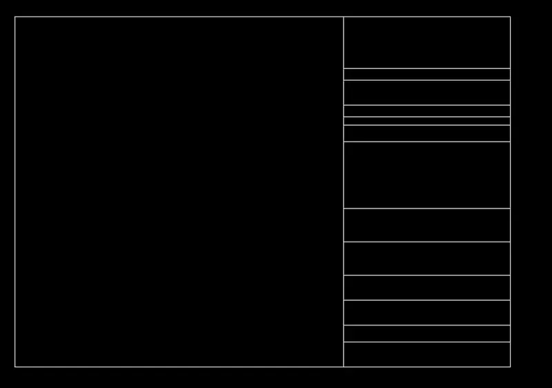
- Usng offset tool and line tool draw the vertical lines.
- Choose 'through' in offset command to give random offset.
- Select the exterior line and assign lineweight of 0.3mm to it.
- Create a new layer in the layer properties naming 'Title block'
- Assign all the objects to this layer.
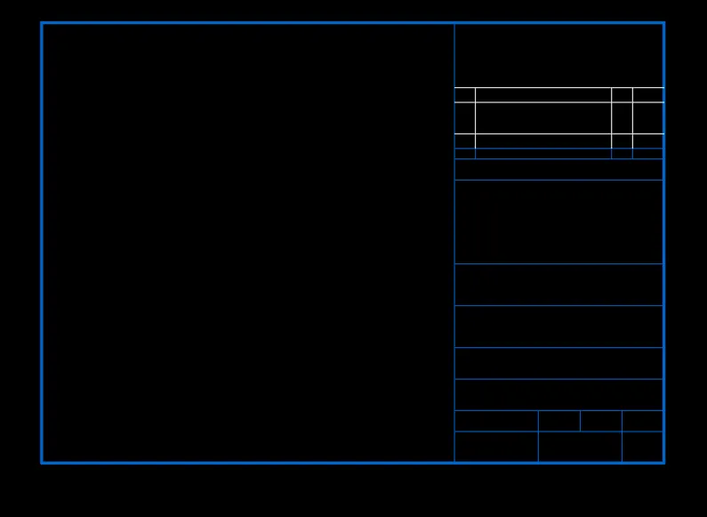
- Go to layer properties and make the title block as current layer.
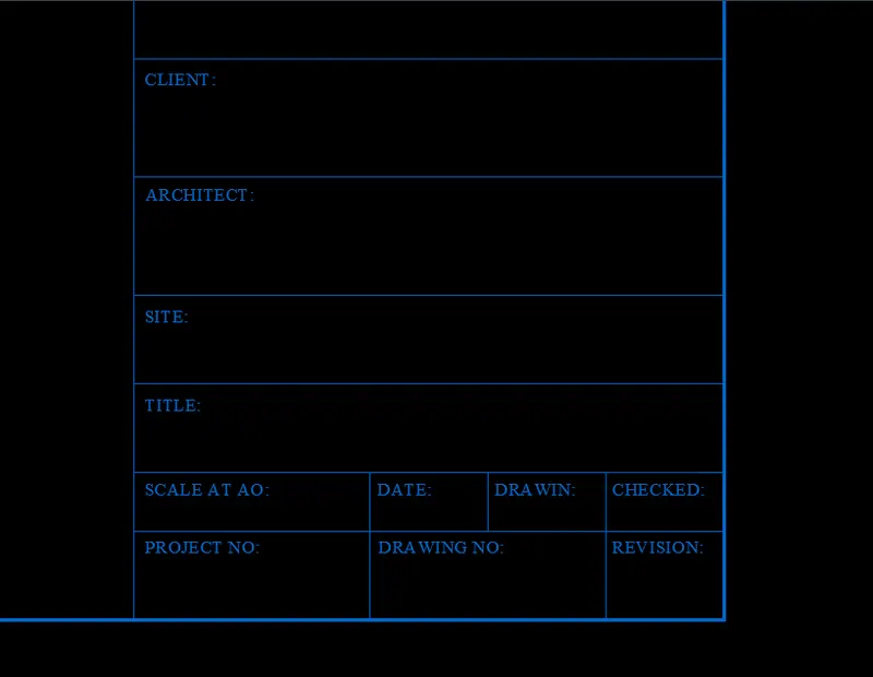
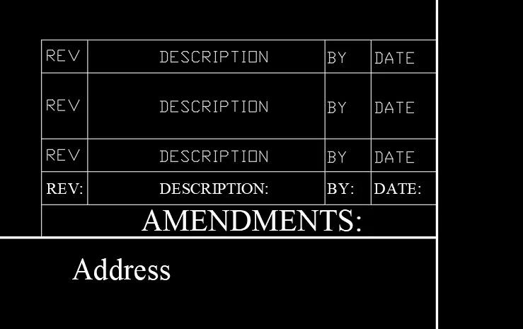
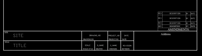
- Using mtext command assign the texts to the table.
- Also scale the texts to fit the table using 'sc' command or 'scaletext' command.
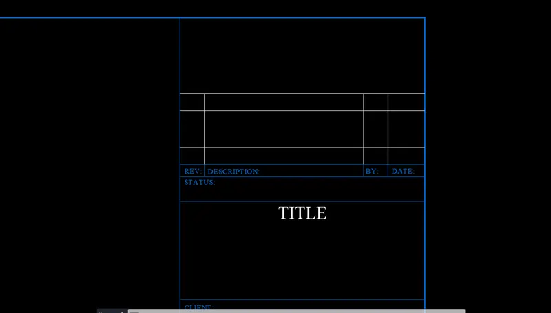
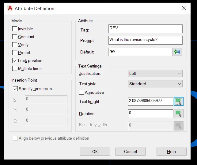
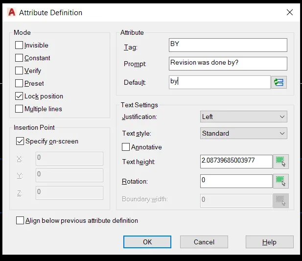
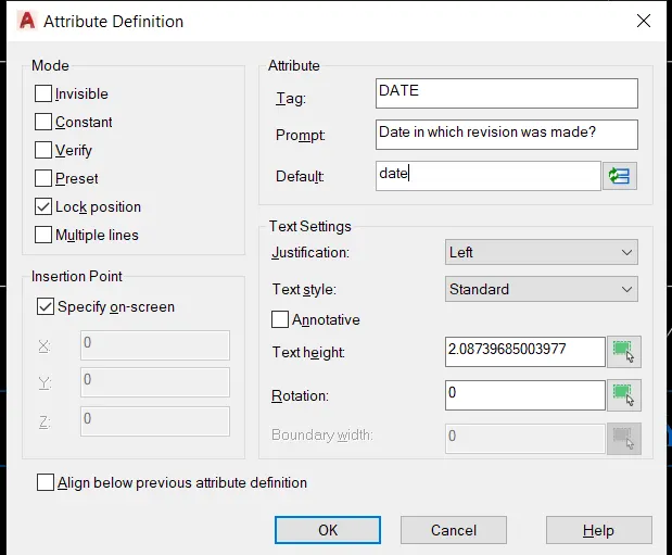
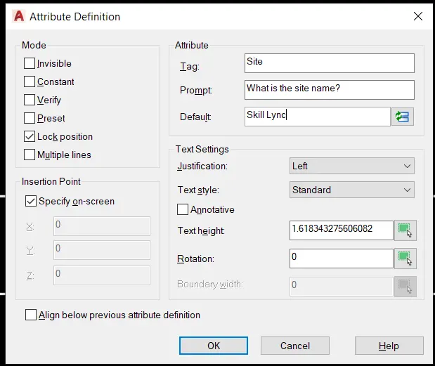
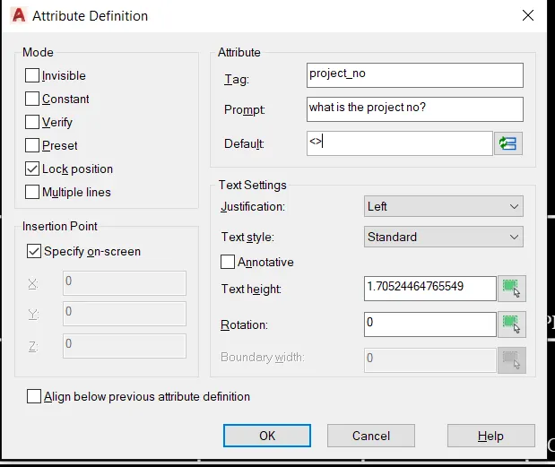
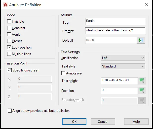
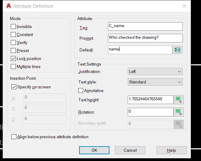
- Type 'attdef' in the command prompt to create attributes.
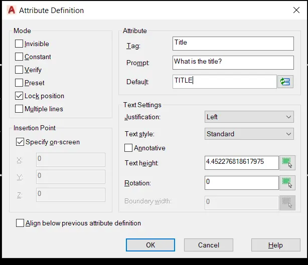
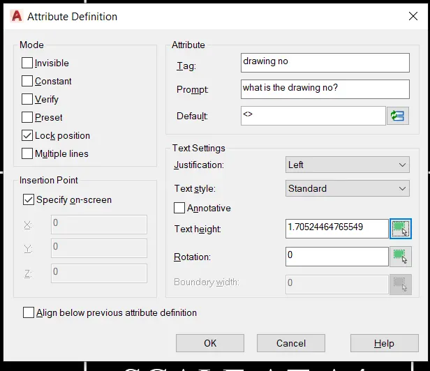
- Provide texts to Tag, Prompt and default, and also select the text height as shown then click ok to insert the attribute in the drawing.
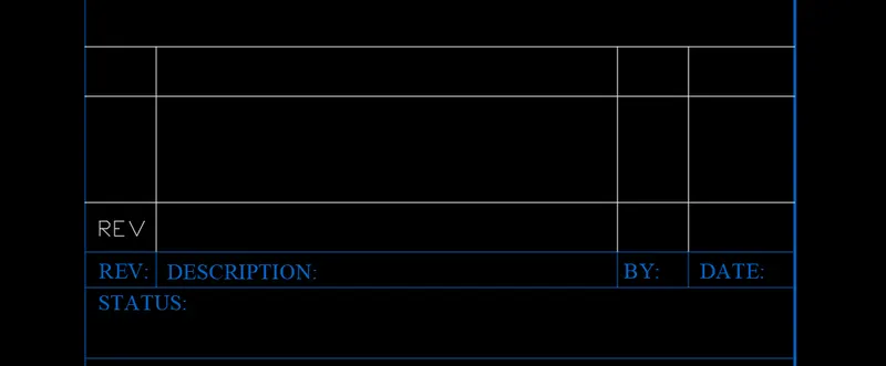
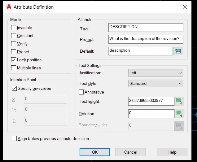
- Again type 'attdef' and follow the above procedure.
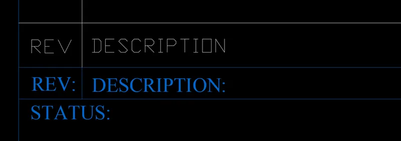
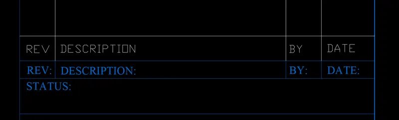
- Using copy tool copy the attributes to the other columns.
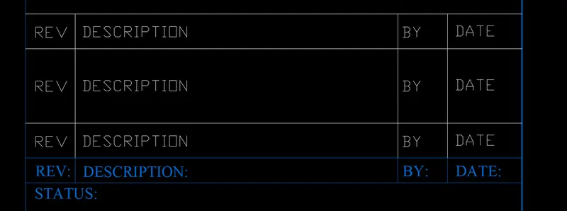
- Now type 'B' to create block.
- Pick a point, select the object and the give a name as 'Custom1_titleblock'. Also specify the other parameters as per preferences and click ok.

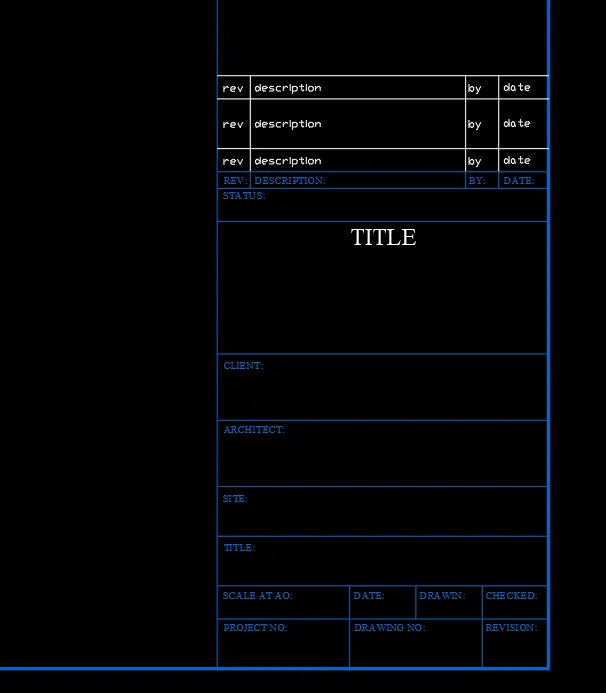
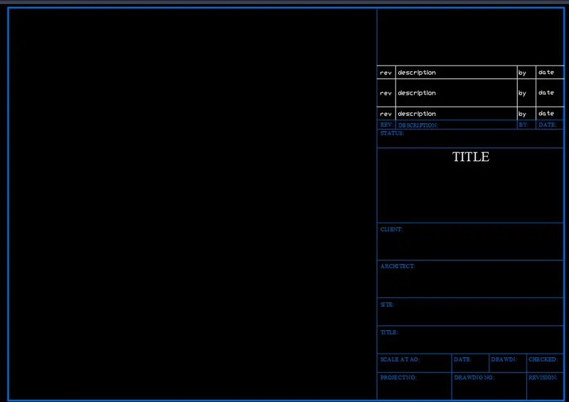
- Type 'bedit' and select the block name 'Custom1_titleblock'.
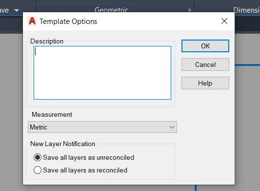
- Choose the file extension to '.dwt'.
- Click on the Save button and type the file name as 'Custom1_titleblock' and click on save.
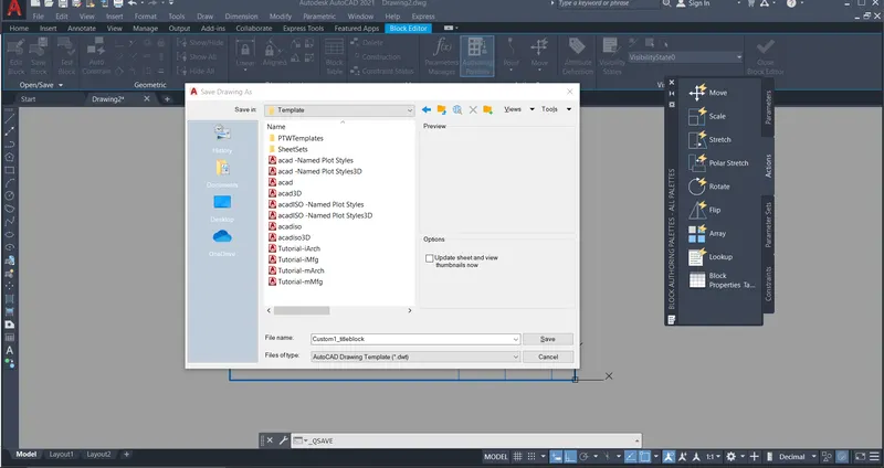
- Now keep the default option and click ok to save it as Template.
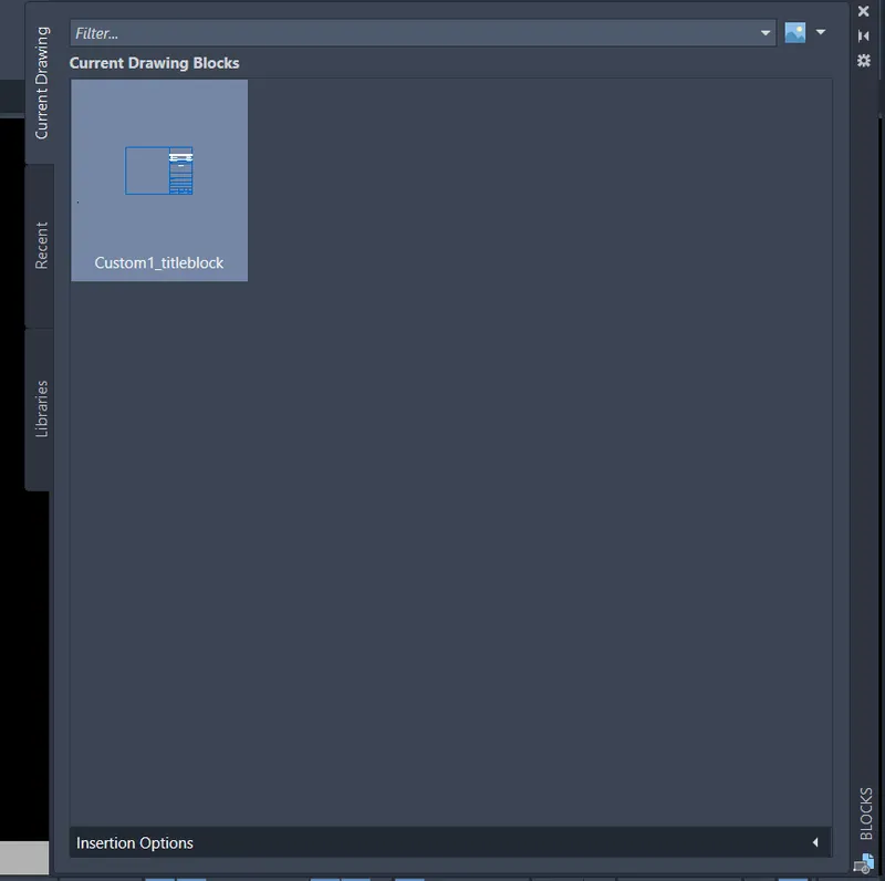
- To insert the block created type 'I' to insert.
- Click on the block created and insert it in the screen.
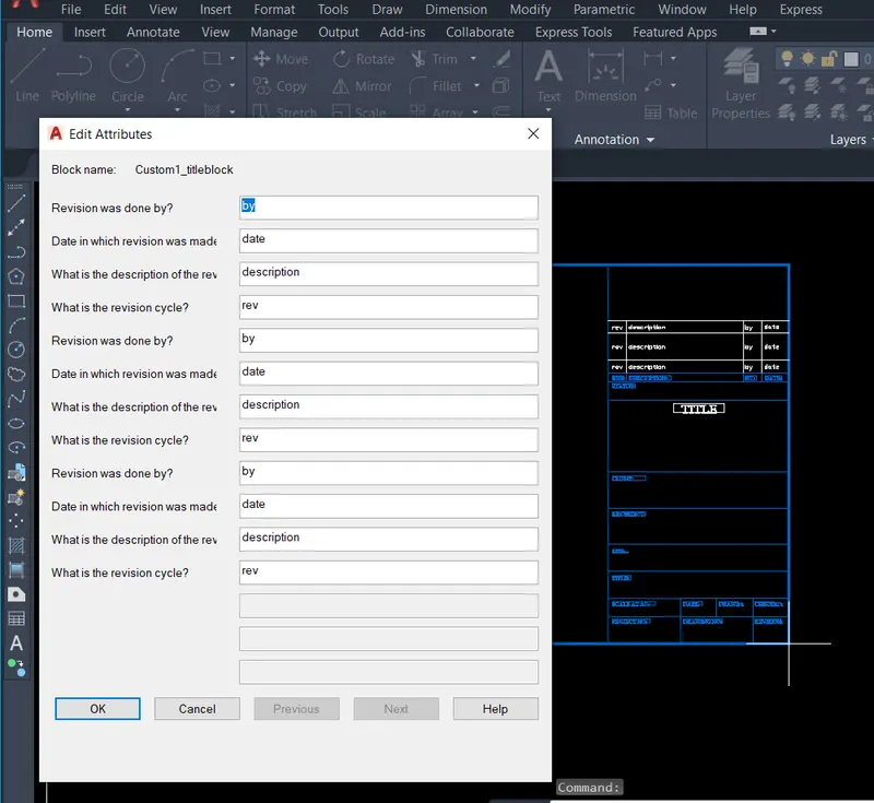
- It will asks to edit the attributes. If needed edit it or keep it default.
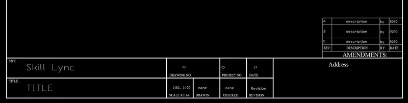
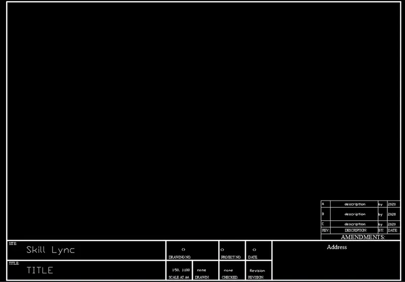
PART B: Creating Custom2_titleblock:
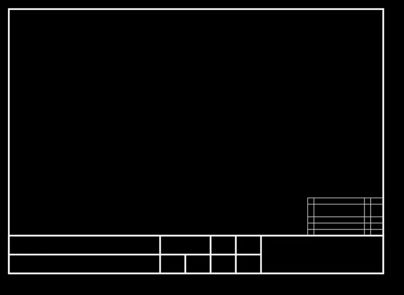
- Type 'Rec' and draw a rectangle of dimension 297,210.
- Select it and type 'x' to explode.
- Offset the bottom horizontal lines at distance 15,15,5,5,5,10,5.
- Using trim tool trim off the unwanted lines.
- Also offset vertical lines choosing 'through' option in the offset command.
- Select the exterior lines and bottom table lines and choose the lineweight as 0.3mm.
- Create a new layer as 'title_block' and assign all the lines and objects to the layer.
- Go to layer properties and select the Title_block as current layer.
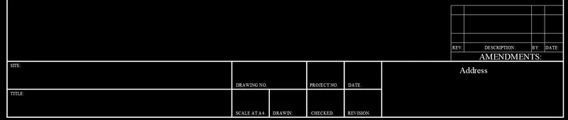
- Using mtext command assign the texts in the drawing.
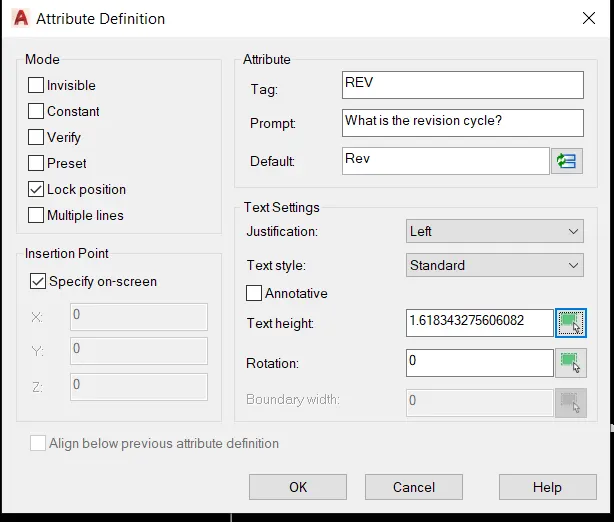
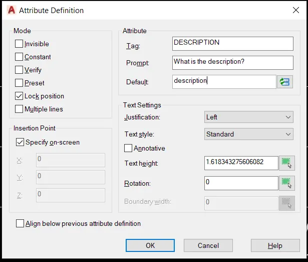
- Using 'Attdef' command create attributes in the drawing.
- Type 'B' to create block.
- Pick a point, select the object and the give a name as 'Custom2_titleblock'. Also specify the other parameters as per preferences and click ok.
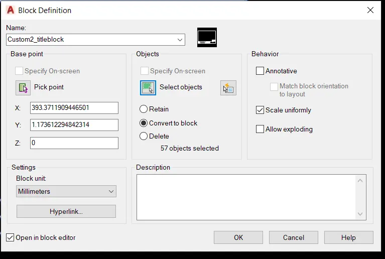
- Type 'Bedit' and select Custom2_titleblock.
- Choose the file extension to '.dwt'.
- Click on the Save button and type the file name as 'Custom2_titleblock' and click on save.
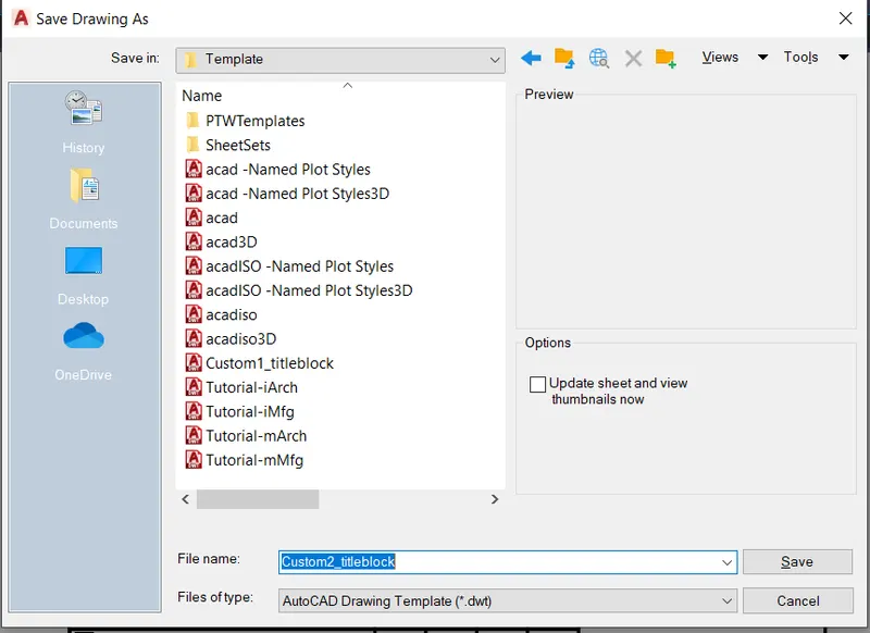
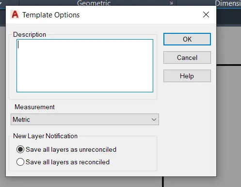
- Now keep the default setting and press OK.
- To insert the block type 'I' and select the block and insert it in the screen.
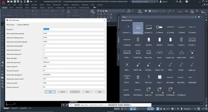
RESULT:
AIM: To create the door types for warehouse and creating blocks for the respective doors using AutoCad.
INTRODUCTION:
- AutoCAD is a commercial computer-aided design (CAD) and drafting software application. Developed and marketed by Autodesk, AutoCAD was first released in December 1982 as a desktop app running on microcomputers with internal graphics controllers. Before AutoCAD was introduced, most commercial CAD programs ran on mainframe computers or minicomputers, with each CAD operator (user) working at a separate graphics terminal. AutoCAD is also available as mobile and web apps.
- AutoCAD is used in industry, by architects, project managers, engineers, graphic designers, city planners and other professionals.
PROCEDURE:
Step 1: Open AutoCAD by clicking on the AutoCAD icon on the Desktop.
Step 2: Start a new project by clicking Ctrl + N on the keyboard. A "Create new drawing" dialogue box will appear.
Step 3: Choose metric option and click OK.
Step 4: Commands used are as follows.
- Type 'UN' in the command prompt and set the units to decimal and set the precision as per the data given and insertion scale as millimeter.
- Type 'Limit' and specify lower unit as 0,0 and upper unit as 10000,10000.
- Type 'Zoom' and select All.
PART A: Creating Door 1:
- Type 'Rec' to invoke rectangle tool.
- Click in the screen to specify first point then type @2330,2750.
- Select the object drawn and type 'X' to explode.
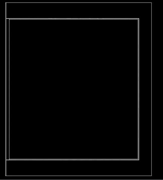
- Type 'O' for offset tool and specify distance 250.
- Offset the top and bottom horizontal lines inward.
- Again type 'O' and specify distance as 200.
- Select the right vertical line and offset it inward.
- Using trim tool trim off the unwanted lines.

- Type 'O' and offset the interior rectangle at a distnace 5 inward.
- Type 'O' and offset the interior rectangle at a distnace 17 inward.
- Type 'O' and offset the right vertical line at a distance 50 inward.
- Type 'F' and fillet the intersected lines.
- Use trim tool to trim off the unwanted lines.
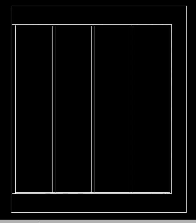
- Type 'Div' then select anyone interior horizontal line and specify the segment as 4.
- Make sure the Node is marked in the object snap.
- Now using Line tool draw vertical lines by choosing first points as the nodes.
- Type 'O' and offset these vertical line at a distance 10 on both sides.
- Using Erase tool erase the unwanted lines.
- Type 'O' and offset the interior horizontal line at a distance 20 inward.
- Using trim tool trim off the unwanted lines.
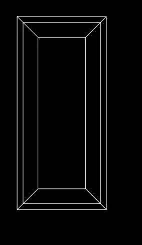
- Type 'rec' and draw a rectangle having size 300,650.
- Type 'O' and offset this rectangle at a distance 20 inward.
- Type 'O' and offset this rectangle at a distance 50 inward.
- Using line tool draw lines connecting each corners of the rectangle.
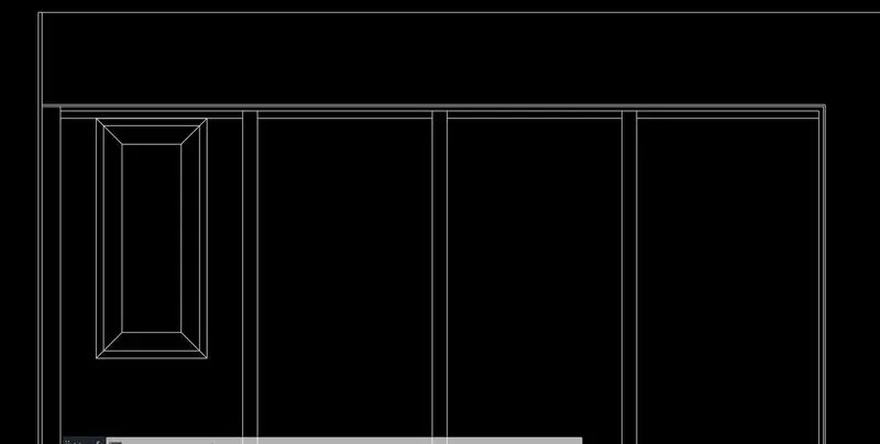
- Copy this Rectangle objects to the mid point of the refrence line previously drawn.
- Type 'Div' and select the right interior vertical line and type 3 for segment number.
- Using line tool draw horizontal refrence lines choosing first point as nodes.
- Type 'Tr' and trim off the vertical line in between horizontal lines.
- Type 'L' and draw a vertical line in the same place where the trimming was done.
- Now Type 'Co' select the entire rectangle and paste it in the mid of the prev vertical line drawn.
- Paste it again in the mid of the bottom refrence line.
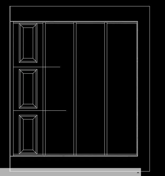
- Using erase tool erase the unwanted lines.
- Now using copy tool copy the three objects and paste it in the mid of the other three boxes.
- Using erase tool erase all the unwated lines.
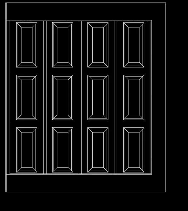
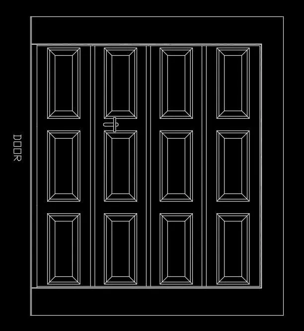
- Using Line tool draw other components of the door.
- Also using mtext command assign texts and using dimlin assign dimensions.
- Create A layer Door and assign the objects to the created layer.
- Using trim tool trim off the unwanted lines.
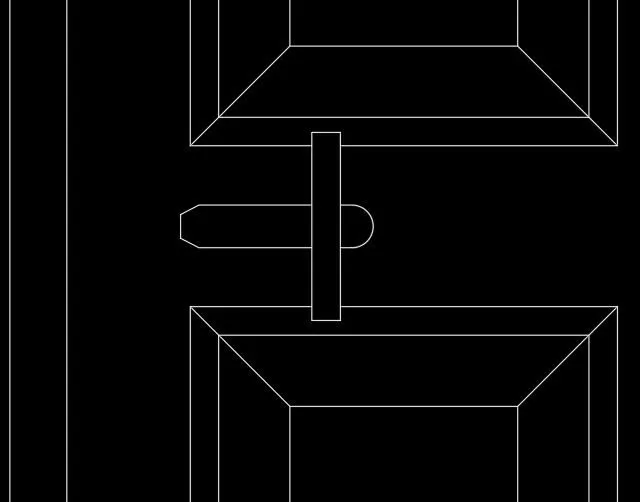
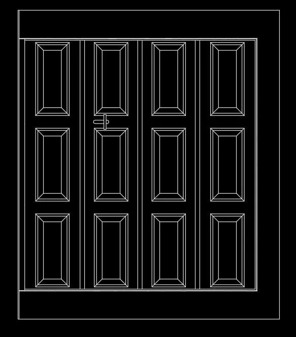
- Type 'Attdef' to define attribute to the drawing.
- Specify the Tag, prompt and default name of the door.
- Also specify the text height and rotation as 270.
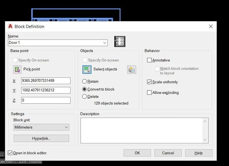
- Now Type 'B' to create block.
- Pick a point by clicking on the left bottom corner of the door.
- Now select the whole object and press enter.
- Specify the block name as 'Door1'.
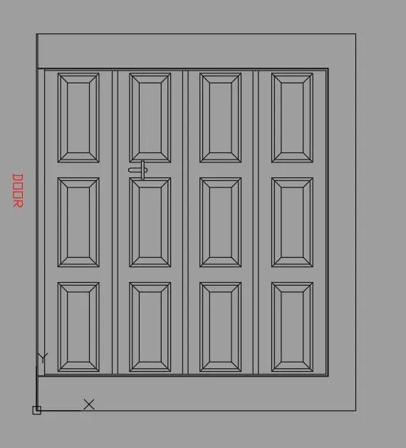
- Now go to block editor and to home and change the colour of the text to red from properties.
- Close the block editor and save the changes.
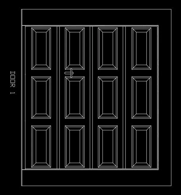
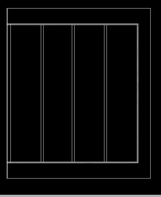
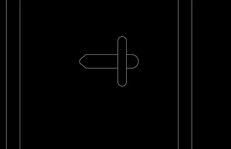
- Type 'Co' and copy the previous drawn object excluding the interior rectangular objects and paste it downward.
- Type 'Attdef' to define attribute to the drawing.
- Specify the Tag, prompt and default name of the door.
- Also specify the text height and rotation as 270.
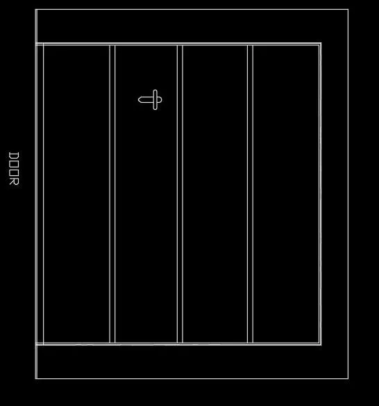
- Now Type 'B' to create block.
- Pick a point by clicking on the left bottom corner of the door.
- Now select the whole object and press enter.
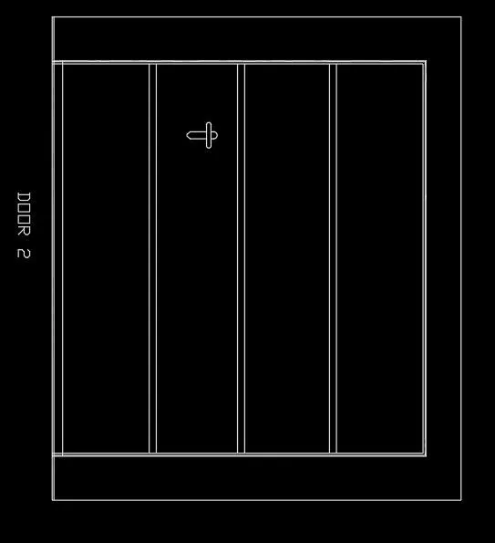
- Specify the block name as 'Door2'.
- Type 'Bedit' and change the colour of the text to red.
RESULT:
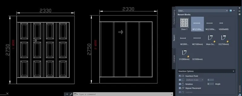
- Type 'I' to insert block and select the Door 1 and insert it in the screen.
- Similarly do the same to insert Door2.
- Using dimlin assign the dimensions.
AIM: To create each electrical symbols as a block with the name given in the legend and also arranging the symbols in the legend using AutoCad.
INTRODUCTION:
- AutoCAD is a commercial computer-aided design (CAD) and drafting software application. Developed and marketed by Autodesk, AutoCAD was first released in December 1982 as a desktop app running on microcomputers with internal graphics controllers. Before AutoCAD was introduced, most commercial CAD programs ran on mainframe computers or minicomputers, with each CAD operator (user) working at a separate graphics terminal. AutoCAD is also available as mobile and web apps.
- AutoCAD is used in industry, by architects, project managers, engineers, graphic designers, city planners and other professionals.
PROCEDURE:
Step 1: Open AutoCAD by clicking on the AutoCAD icon on the Desktop.
Step 2: Start a new project by clicking Ctrl + N on the keyboard. A "Create new drawing" dialogue box will appear.
Step 3: Choose metric option and click OK.
Step 4: Commands used are as follows.
- Type 'UN' in the command prompt and set the units to decimal and set the precision as per the data given and insertion scale as millimeter.
- Type 'Limit' and specify lower unit as 0,0 and upper unit as 10000,10000.
- Type 'Zoom' and select All.
PART A: Creating the Legend table.
- Type 'Rec' for rectangle tool and draw a rectangle with dimension 200,100.
- Now draw horizontal lines using Line tool.
- Using trim tool trim off the unwanted lines.
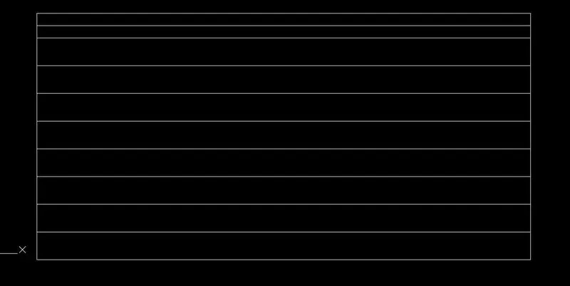
- Type 'O' and specify the offset distance as 20.
- Select the left vertical line and offset it in the right side .
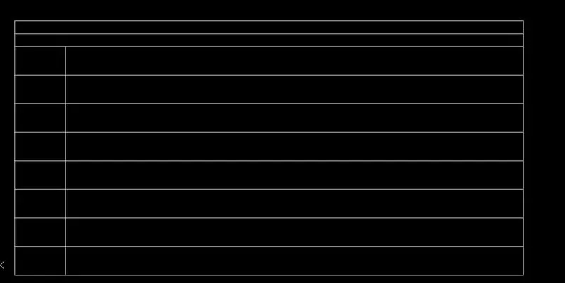
- Using copy tool copy the both vertical lines in the left side and paste it at random distnace in right side.
- Type 'Ex' and select the lines to extend.
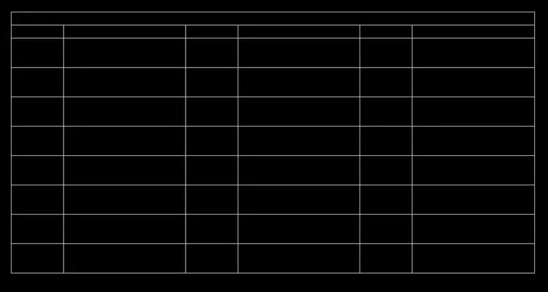
- Using trim tool and line tool do the necessary correction on the bottom right corner.
- Using Mtext command assign the texts in the required positions.
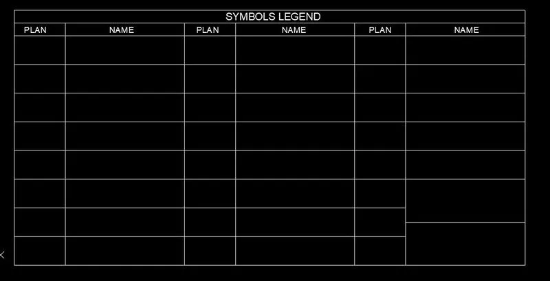
PART B: Drawing different symbols and converting them to blocks.
- Type 'c' and click anywhere in the screen and then enter 1 for radius.
- Type 'L' and then type 'Nea'. Click on the neares point on the circle and draw a slant line.
- Using line tool draw a perpendicular line which connects the previous line.
- Type 'B' to create block.
- Pick a point lets say the center of the circle.
- Now select the whole object and press enter.
- Mark the 'Delete' box.
- Type the name of the object as 'SINGLE GANG SWITCH' and then press OK.

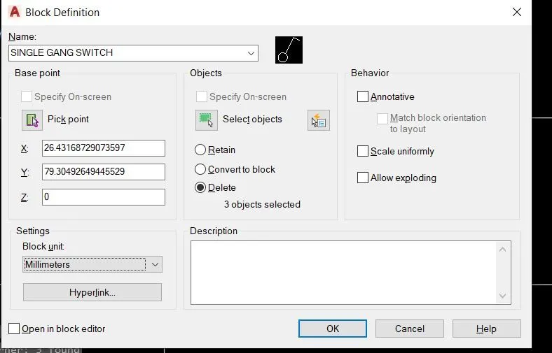
- Similarly draw other symbols using line tool and circle tool and assign them to blocks.

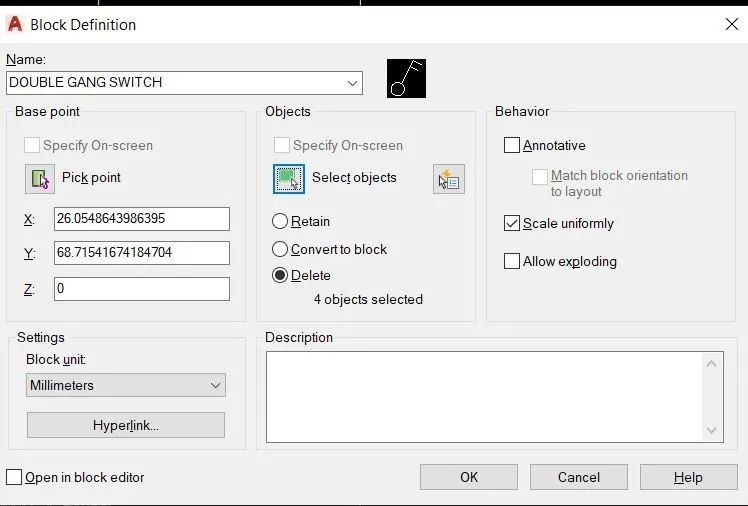
- Following are the blocks created.
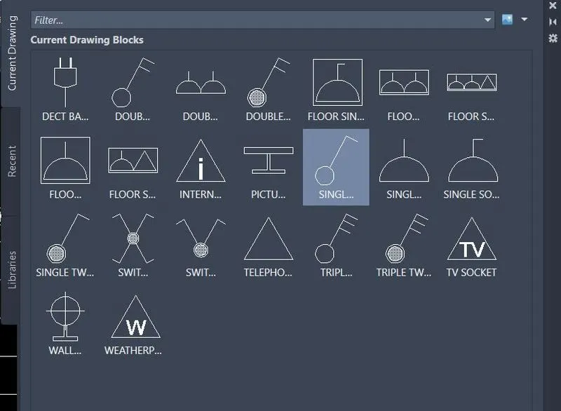
- Now type 'I' to insert the blocks in the respective row and column of the table.
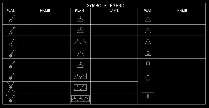
- Now go to the insert panel in the ribbon bar.
- In the data section click on the Field option.
- A Field dialogue box will open.
- Select 'Objects ---> Namedobject'.
- Now select the block names created and click ok to insert them in the respective rows and column.
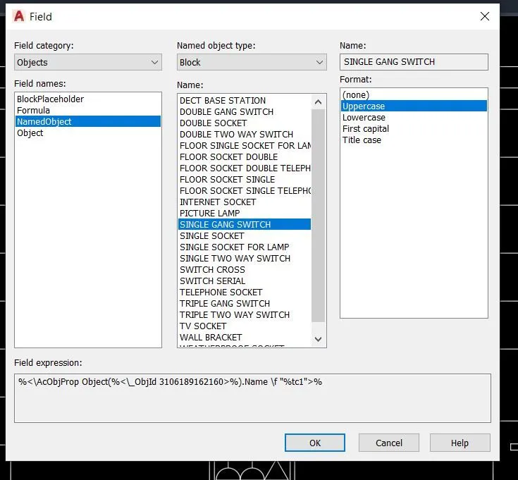
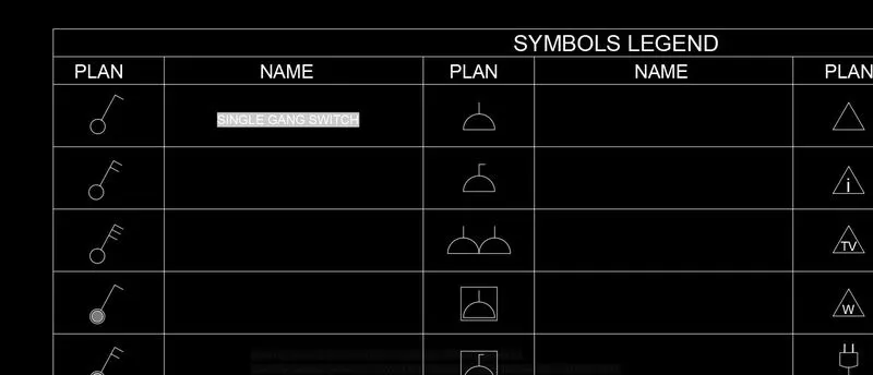
- To remove the boundry layer type 'x' to explode.
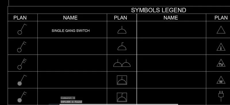
- Using similar procedure insert the block name of the other objects in the respective boxes of the table.
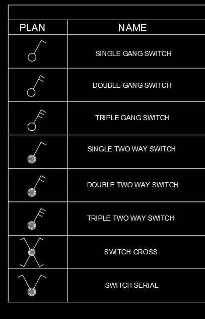
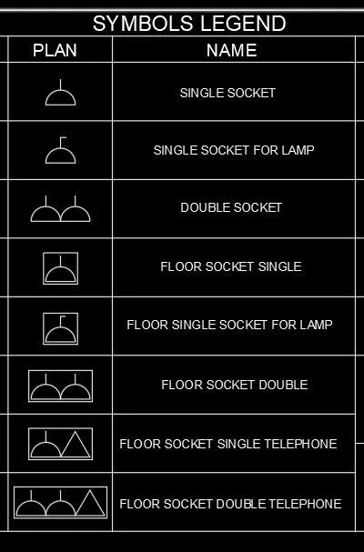
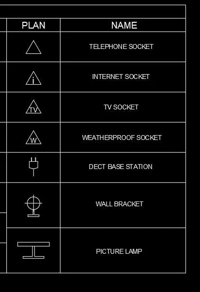
RESULT:
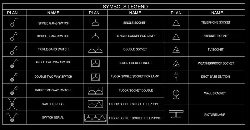
AIM: To create door type of residential building as a block using AutoCad.
INTRODUCTION:
- AutoCAD is a commercial computer-aided design (CAD) and drafting software application. Developed and marketed by Autodesk, AutoCAD was first released in December 1982 as a desktop app running on microcomputers with internal graphics controllers. Before AutoCAD was introduced, most commercial CAD programs ran on mainframe computers or minicomputers, with each CAD operator (user) working at a separate graphics terminal. AutoCAD is also available as mobile and web apps.
- AutoCAD is used in industry, by architects, project managers, engineers, graphic designers, city planners and other professionals.
PROCEDURE:
Step 1: Open AutoCAD by clicking on the AutoCAD icon on the Desktop.
Step 2: Start a new project by clicking Ctrl + N on the keyboard. A "Create new drawing" dialogue box will appear.
Step 3: Choose Imperial option and click OK.
Step 4: Commands used are as follows.
- Type 'UN' in the command prompt and set the units to Engineering and set the precision as per the data given and insertion scale as inches.
- Type 'Limit' and specify lower unit as 0,0 and upper unit as 100,100.
- Type 'Zoom' and select All.
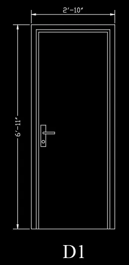
PART A: Creating Door D1:
- Type 'Rec' and click any where in the screen.
- Type @2'-10",6'-11" and press enter.
- Select the rectangle drawn and type 'x' to explode.
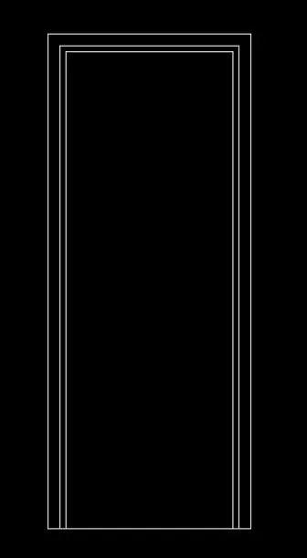
- Type 'O' and specify offset distance as 2" and offset the top horizontal, left and right vertical lines inward.
- Type 'O' and specify offset distance as 1" and offset the offsetted top horizontal, left and right vertical lines inward.
- Using trim tool trim off the unwanted lines.
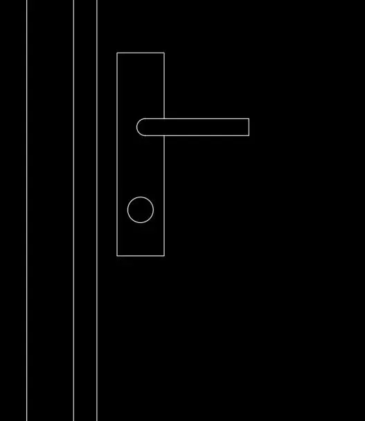
- Now draw the lock part with line and circle tool and also use fillet to modify.
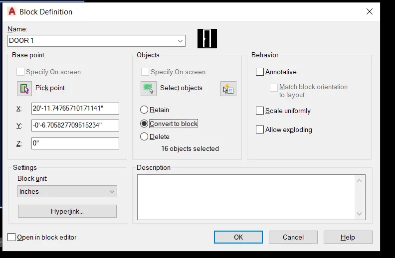
- Type 'b' to create block.
- Pick a point of the object, then select the object, set other options as per preferences then click OK.
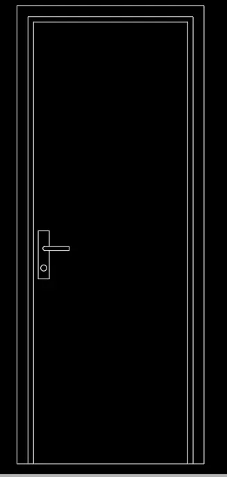
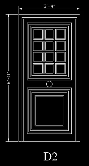
PART B: Creating Door 2:
- The procedure is similar as the Door 1.
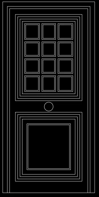
- Draw a rectangle using rectangle tool with dimension 3'-4",6'-11".
- Select the rectangle and type 'X'.
- Using offset tool offset the top left and right line inward with distance 2", 1" and 4"
- Offset the bottom line at 5".
- Using trim tool trim off the unwanted lines.
- Using line tool and offset tool draw the other components of the door with assumed dimensions.
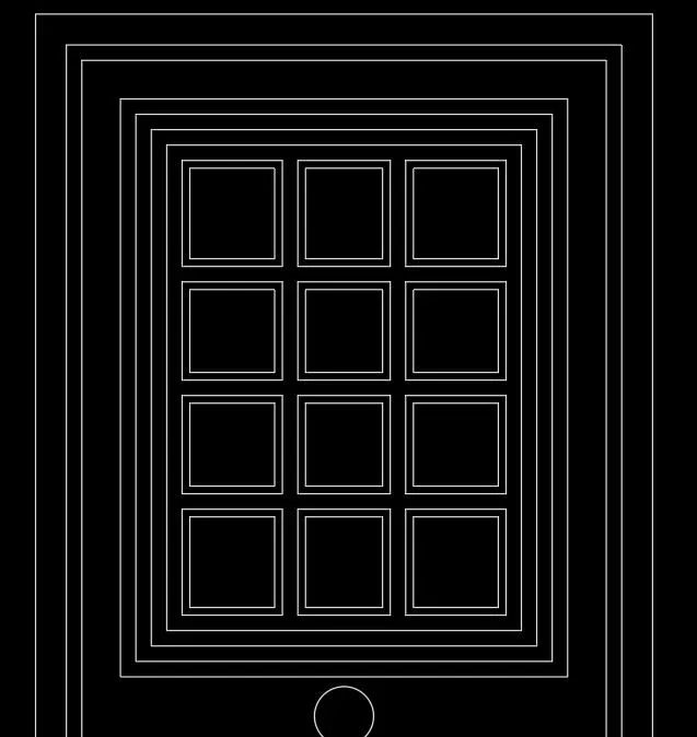
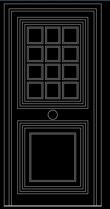
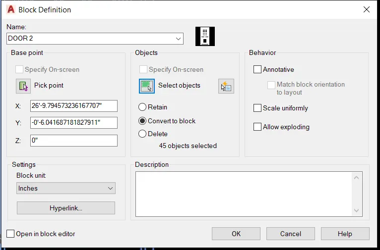
- Type 'B' and create the block. Follow the same procedure as explained in Door 1 drawing.
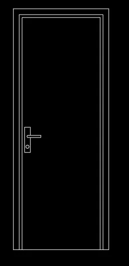
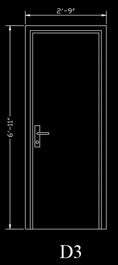
PART C: Creating Door 3:
- Using Copy tool copy the whole door 1 object which was previously drawn.
- Now select all the vertical lines from left and type 'm' to move.
- Move the cursor in the negative x-direction and type distance 1".
- Using trim tool trim off the unwanted lines.
- Therfore the new dimension of the door becomes 2'-9", 6-11".
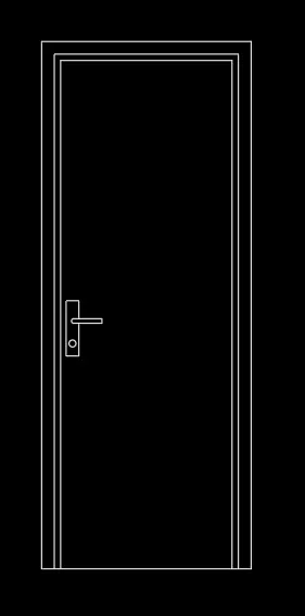
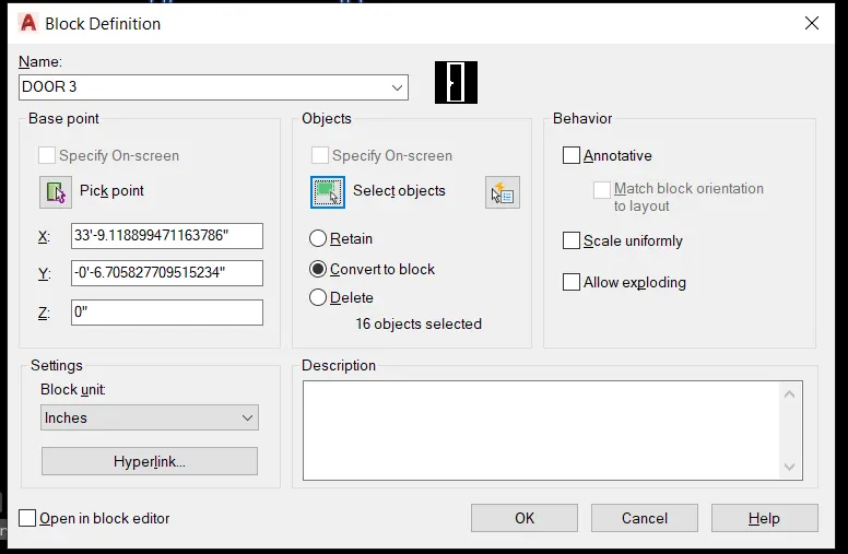
- Type 'B' and create block by above mentioned procedure.
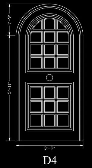
PART D: Creating Door 4:
- Using rectangle tool draw a rectangle with dimension 3'-9",7'-8".
- Select the rectangle and type 'X' to explode.
- Type 'O' and offset the top horizontal line at a distance 1'-9" downward.
- Using arc tool and selecting 3 point method draw an arc.

- Using trim tool trim off the unwanted lines.
- Using offset tool offset the vertical lines, horizontal lines and arc at a distance 1.5", 1", 4".
- Using trim tool trim off the unwanted lines.
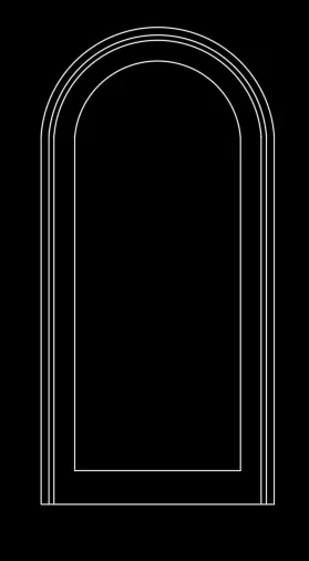
- Similarly using line tool, offset and circle tool tool draw the other aspects of the door.
- To modify it use trim tool, erase tool and fillet tool wherever required.
- Type 'B' and create block by above mentioned method.
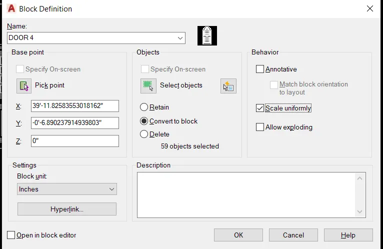
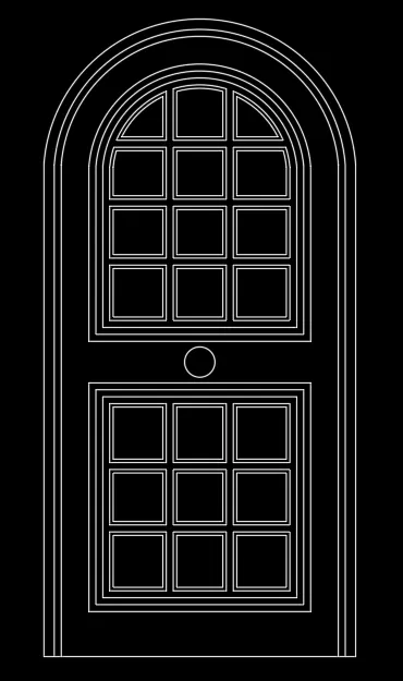
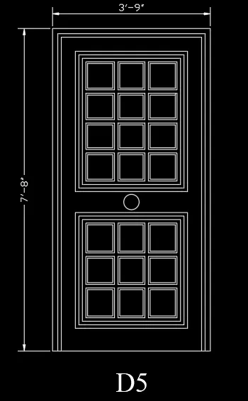
PART E: Creating Door 5:
- Copy the Door 4 and paste it beside it.
- Using line tool draw a line tangent to the top point of arc.
- Copy the tangent line and paste it in every arc top tangent point.
- Using Extend tool extend all the vertical lines.
- Using Fillet tool and radius 0, fillet all the extendel lines to the respective horizontal lines.
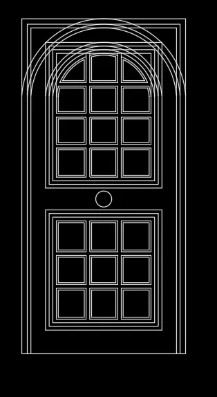
- Now using erase tool erase all the arcs.
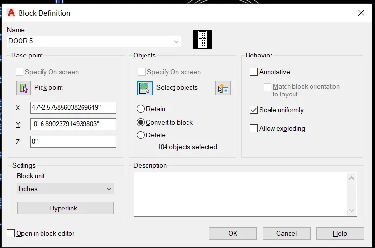
- Type 'B' and create block following above mentioned procedure.
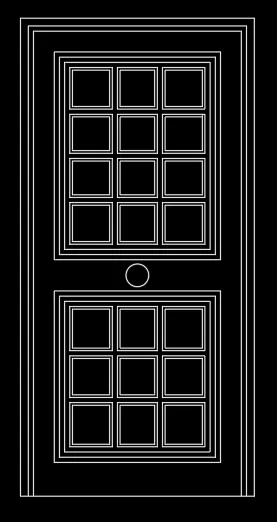
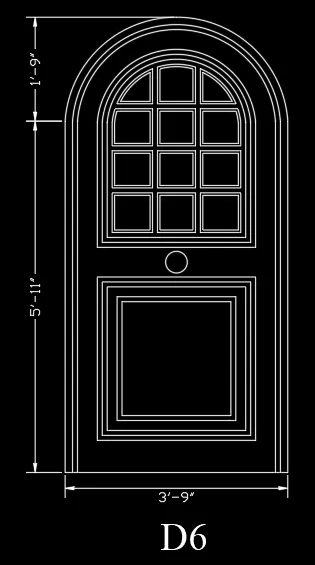
PART F: Creating Door 6:
- Copy the Door 4 and paste it beside it.
- Using erase tool erase the bottom small rectangles.
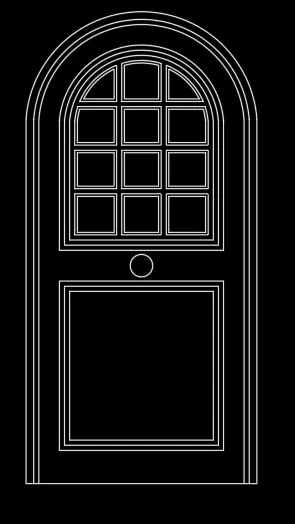
- Using Offset tool draw the other aspects of the drawing.
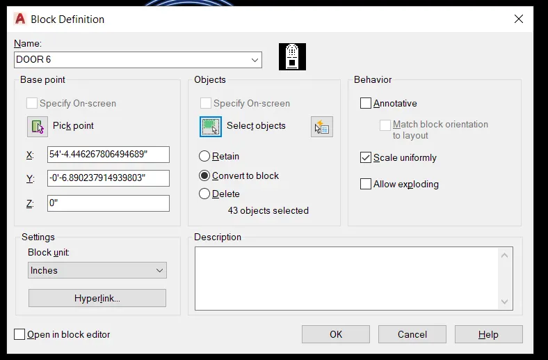
- Type 'B' to create block as mentioned above.
RESULT:
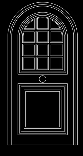
- Following are the objects created. (This dialogue box comes by typing 'I' to insert the block in the screen.)
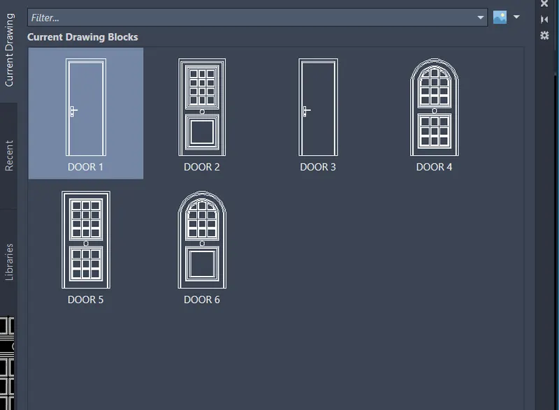
- Using mtext and dimlin command assign texts and dimensions wherever required.
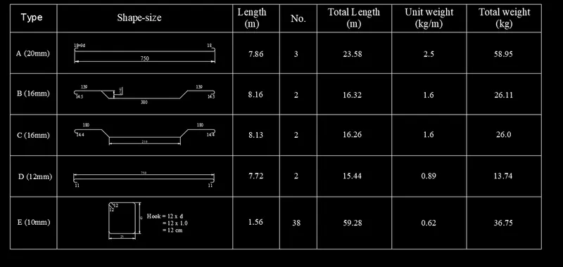
AIM: To create each shape as block and insert them in a table using AutoCad.
INTRODUCTION:
- AutoCAD is a commercial computer-aided design (CAD) and drafting software application. Developed and marketed by Autodesk, AutoCAD was first released in December 1982 as a desktop app running on microcomputers with internal graphics controllers. Before AutoCAD was introduced, most commercial CAD programs ran on mainframe computers or minicomputers, with each CAD operator (user) working at a separate graphics terminal. AutoCAD is also available as mobile and web apps.
- AutoCAD is used in industry, by architects, project managers, engineers, graphic designers, city planners and other professionals.
PROCEDURE:
Step 1: Open AutoCAD by clicking on the AutoCAD icon on the Desktop.
Step 2: Start a new project by clicking Ctrl + N on the keyboard. A "Create new drawing" dialogue box will appear.
Step 3: Choose metric option and click OK.
Step 4: Commands used are as follows.
- Type 'UN' in the command prompt and set the units to decimal and set the precision as per the data given and insertion scale as millimeter.
- Type 'Limit' and specify lower unit as 0,0 and upper unit as 10000,10000.
- Type 'Zoom' and select All.
PART 1 : Creating Shapes and blocks.
- Draw a Line using line tool of length 750.
- Type 'O' for offset and specify offset distance as 18.
- Select the line and offset it upward.
- Join the line using line tool.
- Offset the vertical lines at a distance 9 inward
- Trim the horizontal line between the offset.
- Type 'F' and type radius as 18 and fillet both horizontal line in both sides.
- Using trim tool trim off the unwanted lines.
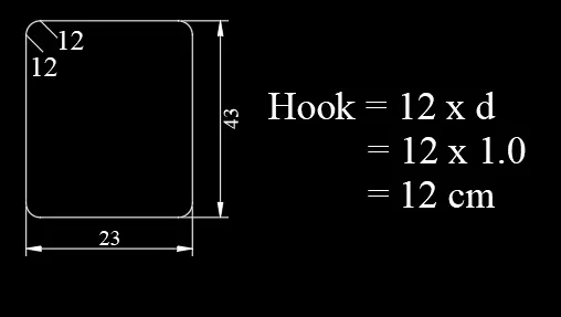
- Using mtext and dimlin command assign the dimension and texts.
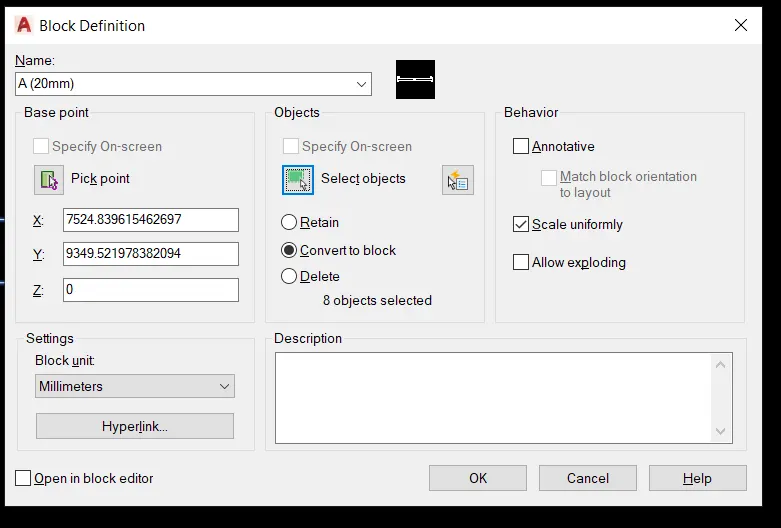
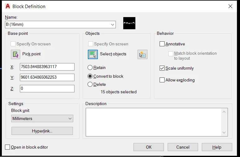
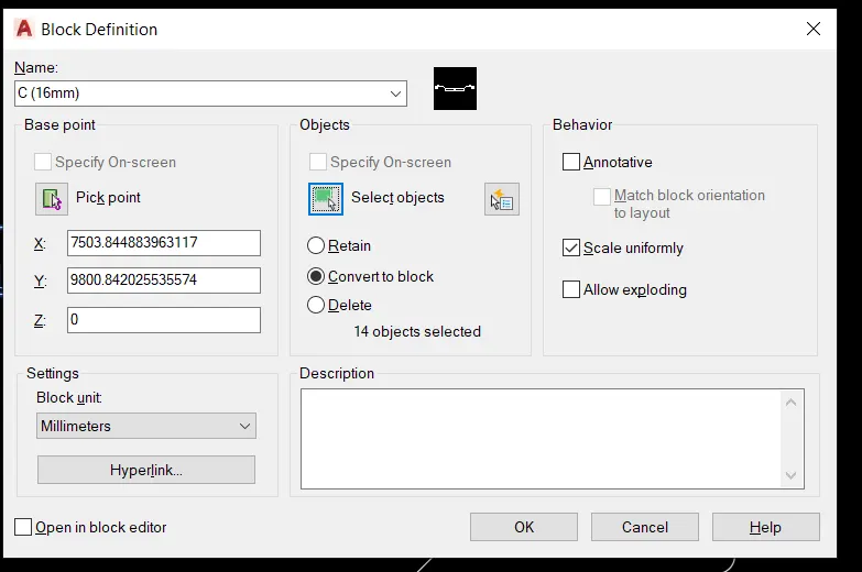
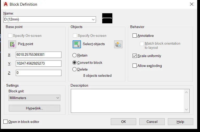
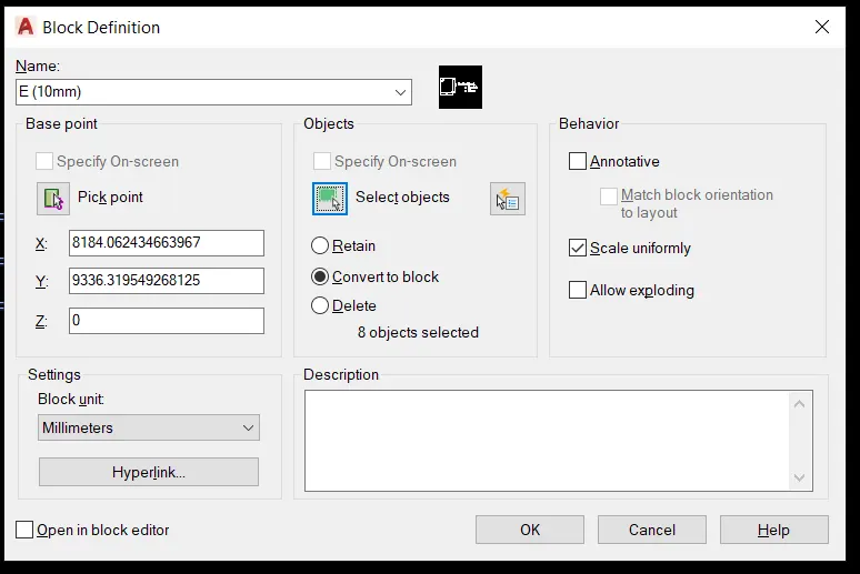
- Type 'B' to insert block.
- Pick a point lets say the mid point.
- Type the name of the Block as 'A (20mm)'
- Select the object and press enter.
- Set the other properties as per preferences and then click ok.
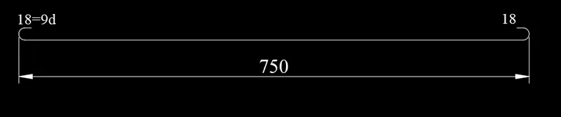
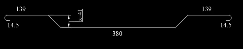
- Similarly draw other figures using line tool, offset tool and fillet tool.
- Also using 'B' command create blocks by above mentioned procedure.


PART 2: Creating the table:
- Using line tool and offset tool draw the table.
- Use trim command to trim off the unwanted lines.
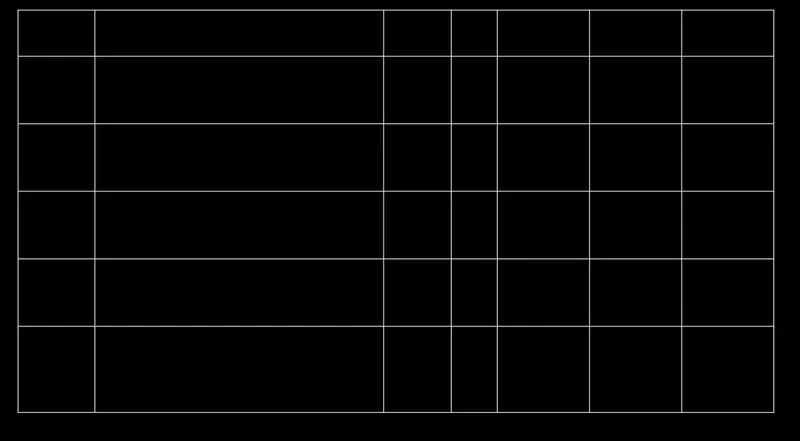
- Using mtext command assign the heading texts. Set justification to center.
- Type 'I' to insert block.
- Select the blocks and place them in respective positions in the table.
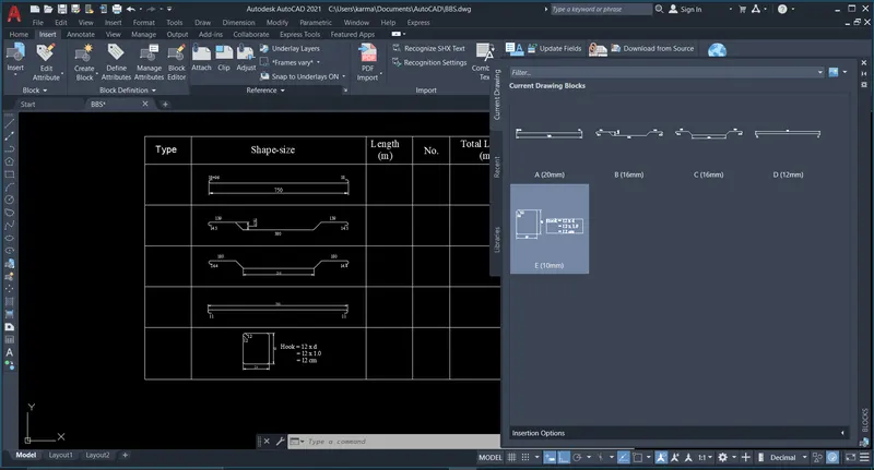
- Now go to insert panel and click on the Field.
- Select the namedobject.
- Select the block names and place them in respective positions in first column.
- Using mtext command fill the other columns.
RESULT: