Project 1 _Creating an Architectural plan for the provided plot size and develop relevant basic structural drawings
AIM: To design and draft layout of a residential building having plot size 60'x20' (18.3mx6m).
INTRODUCTION:
- AutoCAD is a commercial computer-aided design (CAD) and drafting software application. Developed and marketed by Autodesk, AutoCAD was first released in December 1982 as a desktop app running on microcomputers with internal graphics controllers. Before AutoCAD was introduced, most commercial CAD programs ran on mainframe computers or minicomputers, with each CAD operator (user) working at a separate graphics terminal. AutoCAD is also available as mobile and web apps.
- AutoCAD is used in industry, by architects, project managers, engineers, graphic designers, city planners and other professionals.
- The Dimensions assumed for exterior wall is 230mm (9") and interior wall is 120mm (4.5")
- The dimensions of the doors and windows are assumed as follows:
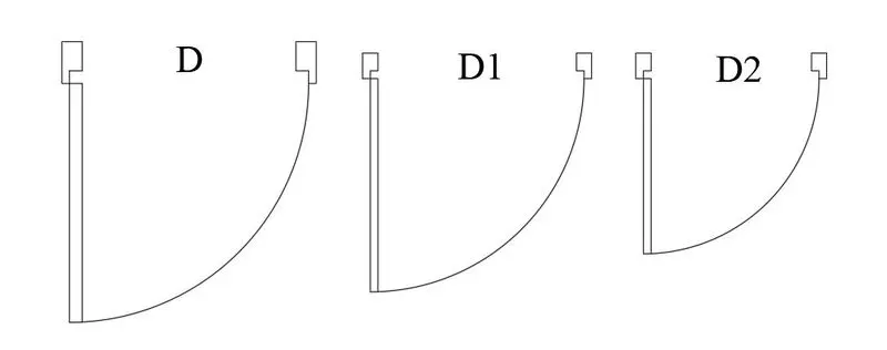
- Main door D = 1000x2100
- D1= 750 X 2100
- D2= 900 X 2100
- W=1500X1200
- W1= 1200X1200
- W2=1000X1500
- W3=900x1200
- W4=600X600
- The column dimension is assumed as 230X350mm and 230X400mm
- Depth of Slab is assumed as 100mm
- The basic autocad tools that can be used to draw the plan, section and elevation are draw tools and modify tools.
Following are the drawings to be made:
- Architectural Drawings:
- Site Plan Layout
- Ground Floor Plan
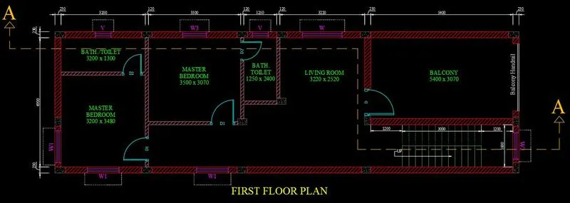
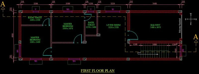
- First Floor Plan
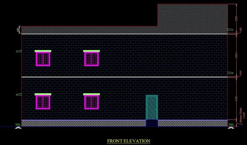
- Elevation
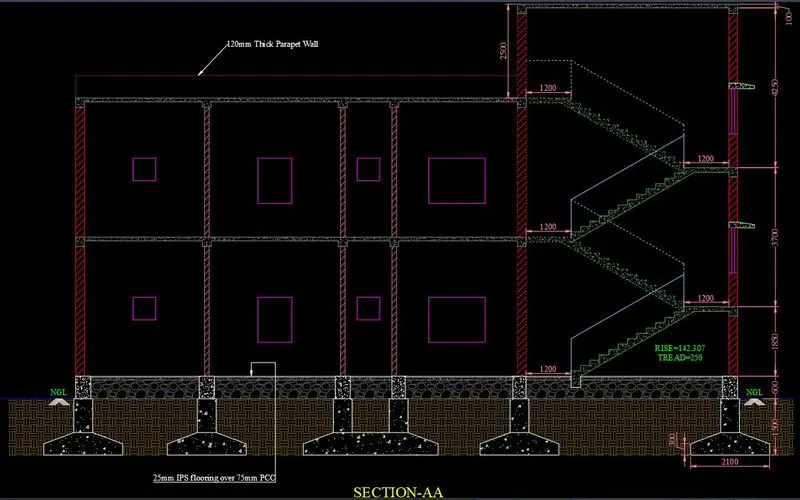
- Section
2. Structural Drawings:
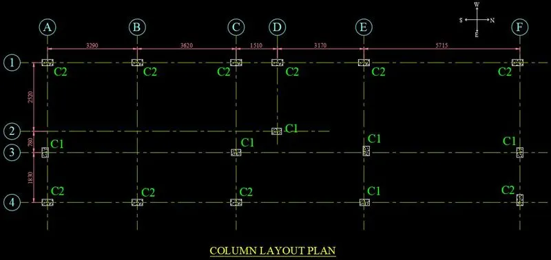
- Column Layout Plan
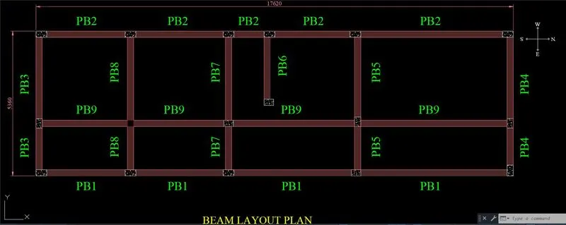
- Beam Layout Plan
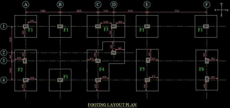
- Footing Layout Plan
PROCEDURE:
Step 1: Open AutoCAD by clicking on the AutoCAD icon on the Desktop.
Step 2: Start a new project by clicking Ctrl + N on the keyboard. A "Create new drawing" dialogue box will appear.
Step 3: Choose metric option and click OK.
Step 4: Commands used are as follows.
- Type 'UN' in the command prompt and set the units to decimal and set the precision as per the data given and insertion scale as millimeter.
- Type 'Limit' and specify lower unit as 0,0 and upper unit as 50000,50000.
- Type 'Zoom' and select All.
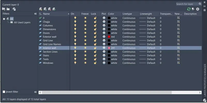
- Go to layer properties and create new layers as follows (Later on we can add more distinct colours to the layers).
1) ARCHITECTURAL DRAWING:-
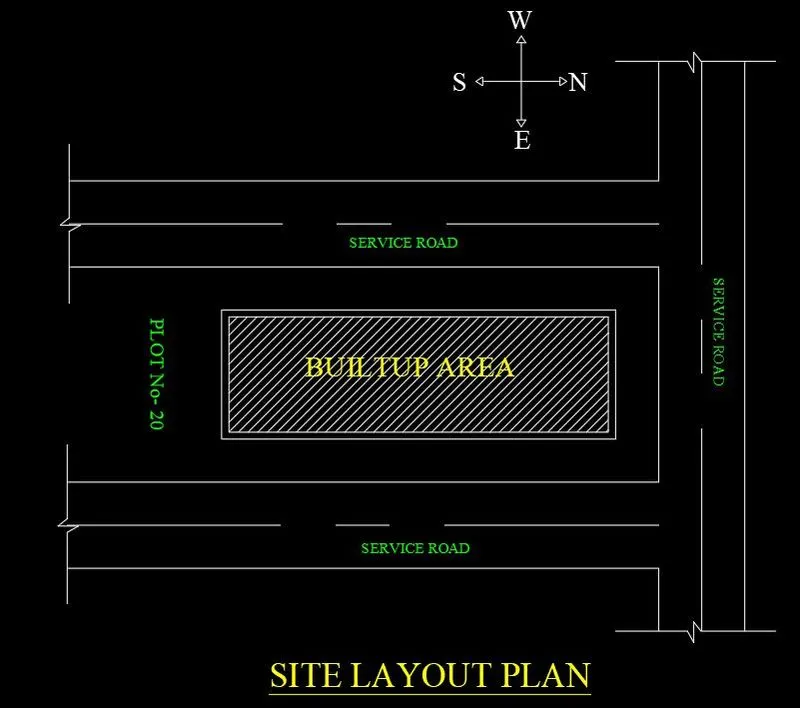
PART A: Preparing SITE LAYOUT PLAN:
- Type 'Rec' to invoke rectangle tool and click on the screen to specify the first point
- Type @18300,6000 and click enter.
- Select the above object and type 'X' to explode.
- Now type 'O' for offset tool and specify the offset distnace as 340.
- Offset the vertical lines inward.
- Type 'O' for offset tool and specify the offset distance as 320.
- Offset the horizontal lines inward.
- Type 'F' to invoke fillet tool and select radius as 0, now fillet the interior lines.
- Type 'O' for offset tool and specify the offset distance as 2000.
- Click on the top exterior line and offset it outward.
- Similarly offset the bottom exterior line and right exterior line outward.
- Type 'O' for offset tool and specify the offset distance as 4000 to define the roads.
- Click on the last offsetted lines and click outward.
- Using fillet command fillet the lines to meet them.
- Now using line tool draw the Jagged lines.
- Use trim tool to trim off the unwated lines.
- Type 'h' to invoke hatch tool and select Ansi-131 and hatch the interior rectangle.
- Type 'mtext' and specify the texts wherever required.
- Assign the texts to respective layers.
- Using Line tool draw the cardinal directions.
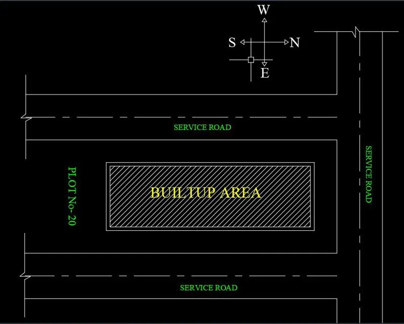
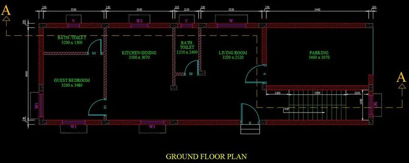
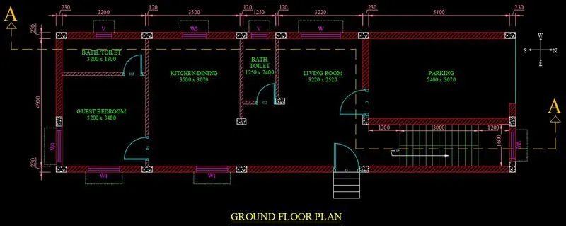
PART B: Preparing the Architectural Ground Floor Plan:
- The Plot size given is 18.3mx6m therefore taking an offset of around 340mm and 320mm inward. This is the builtup area.
- Go to layer properties and select the exterior wall as current layer.
- Type 'L' to invoke line tool and click anywhere to specify the first point.
- Having othro on type 18300 in positive x-direction.
- Type 6000 in positive Y-direction.
- Type 18300 in negative X-direction.
- Type 'C' to close the line.
- Now Type 'O' to invoke the offset tool and specify the offset distance as 320.
- Click the Longest line and offset it inwards.
- Similarly click the second longest line and offset it inwards.
- Press Esc to cancel the command.
- Type 'O' to invoke the offset tool and specify the offset distance as 340.
- Click the first shortest line and offset it inwards.
- Click the second shortest line and offset it inwards.
- Type 'F' for fillet and choose radius as 0 and also choose multiple option and then fillet all the interior lines.
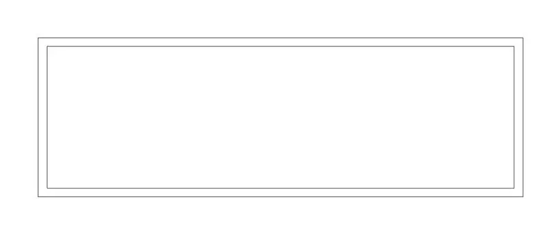
- Use erase tool to erase the exterior line.
- So the builtup area is 17620x5360.
- Type 'O' for offset tool and specify the offset distance as 230.
- Click on any line and offset it inward.
- Follow the same of other lines.
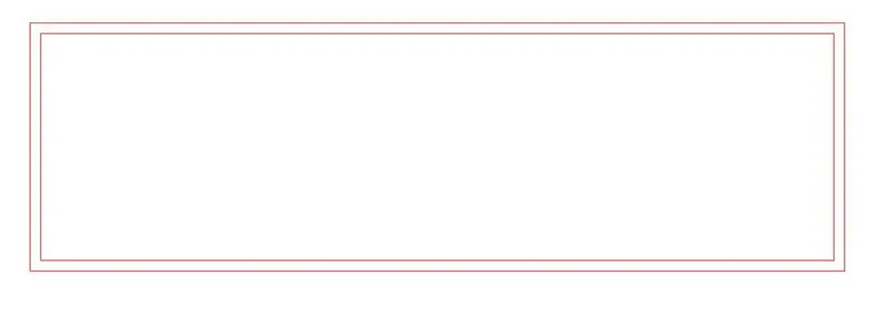
- Type 'O' for offset tool and specify the offset distance as 3200.
- Click on the second vertical line from the left side and offset it in the right side.
- Type 'O' for offset tool and specify the offset distance as 120.
- Click on the last offsetted line and offset it in the right side.
- Type 'O' for offset tool and specify the offset distance as 1300.
- Click on the second vertical line from the top side and offset it in downward.
- Type 'O' for offset tool and specify the offset distance as 120.
- Click on the last offsetted line and offset it in the downward direction.
- Now make door openings by taking offset at a distance 750 (for bathroom and W/C) and 900 (for Bedroom).
- Using trim tool, trim off the unwanted lines.
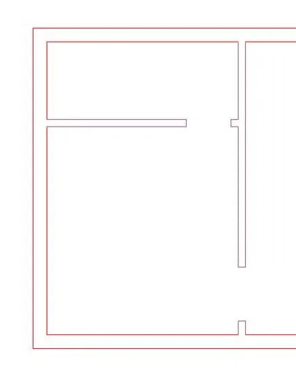
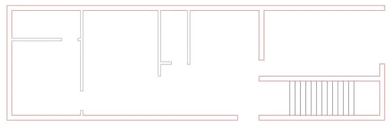
- Similarly using offset tool offset the vertical lines at a distance 3500,120,1250,120,3220,230.
- Also using offset tool offset the horizontal lines at a distance 2400,3070 and 230.
- Now using Trim tool trim off the unwanted lines.
- Using offset tool draw the door openings at offset distance 750(for bathroom and W/C), 900(for bedroom ) and 1000(as main door).
- Using offset tool and offset distance as 1200(for midlanding) and 250(tread) draw the stairs.
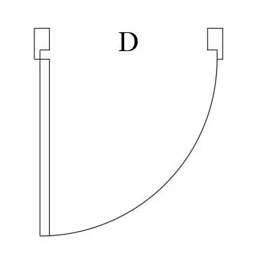
- Now using line tool and arc tool draw doors, windows and ventilator in a different drawing space.
- Type 'L' for line tool and draw line of distance 1000.
- Now draw hinges and door frame using line tool.
- Move the door frame and hinge object and drag it to the end point of the line previously drawn.
- Now type 'Mi' for mirror tool and mirror the door frame and hinge object by choosing the reflection point as the mid point of the previous drawn line.
- Draw the door panel using line tool and using circle tool draw the arc.
- Trim off the unwanted lines using trim tool.
- Now type 'attdef' to invoke attribute definition dialogue box.
- In the tag box type 'Door_no'
- In the Prompt box type 'What is the door number?'
- In the Defaut box type 'D'.
- Set justification as center.
- Select the text height as 100
- Click Ok.
- Now type 'B' to invoke the Block definition dialogue box.
- Type Name as 'Main door (D1000)'
- Select the insertion point as the end point
- Select the object and then mark the 'convert to block'.
- Click OK.
- Type 'Bedit' to invoke block editor screen space.
- Select the Object drawn and press enter
- Now assign Flip-dynamics to the object by setting the parameter as Flip and also setting the action to Flip
- Save the changes and close the block editor.
- Similarly create other doors, windows and ventilators and define attributes and blocks.
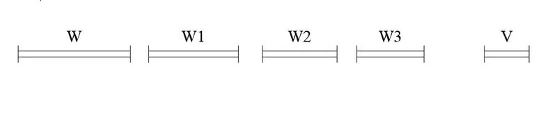
- Now type 'I' to invoke block insertion dialogue box and insert the blocks previously made in respective positions.
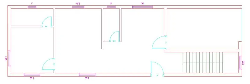
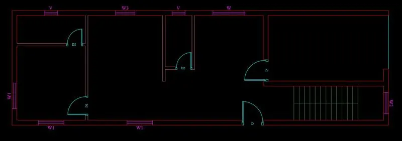
- Changing the display colour to black by going to the option dialogue box.
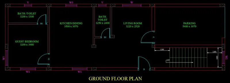
- Type 'mtext' and insert texts wherever required.
- Using 'dimlin' tool assign the dimensions wherever required.
- Now Go to layer properties and select the column layer as current.
- Now draw two rectangles using 'rec' tool with size 230x350 and 230x400.
- Type 'hatch' and hatch the column area by selecting AR-conc.
- Now using copy tool assign the columns in its repective positions.
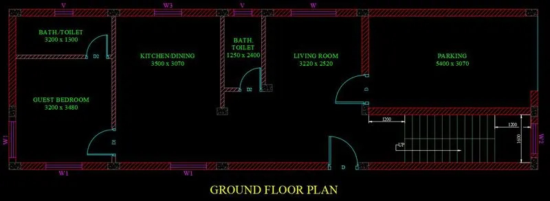
- Set Exterior walls as current layer by going to layer properties.
- Type 'h' and click on Ansi-131 and set scale as 30.
- Hatch all the exterior walls.
- Follow the same procedure for interior walls.
- Set Dimensions as current layer.
- Using Dimlin command assign the other dimensions.
- Draw section line using line tool and select the line type as Dashed.
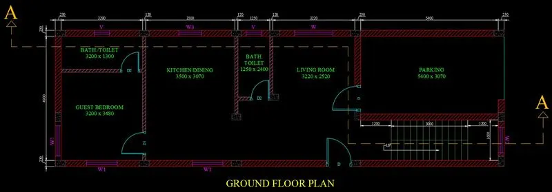
- Using Line tool Draw the Chajja and select the line type as Hidden.
PART B: Preparing the Architectural First Floor Plan:
- Type 'Co' to invoke copy tool and select the enire Ground floor objects and press enter.
- Click any corner point as the base point and paste the copied object in the right side.
- Now using Line tool edit the existing drawing.
- Use Textedit command to edit the texts wherever required.
- Adjust the door openings using offset and trim tool and move the door objects to the required position using Move tool.
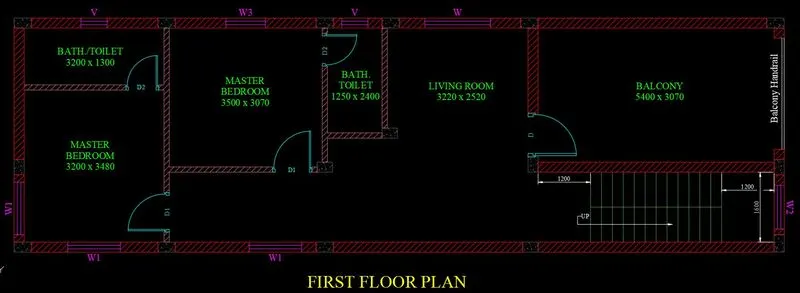
- Set Dimensions as current layer.
- Using Dimlin command assign the other dimensions.
- Draw section line using line tool and select the line type as Dashed.
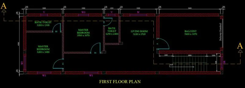
- Using Line tool Draw the Chajja and select the line type as Hidden.
PART C: Preparing Front Elevation:
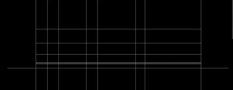
- Type 'XL' and choose vertical lines.
- Select all the end points of the front objects line walls, windows, doors and chajjas.
- Now draw a horizontal line intersecting all the vertical construction lines. This line will be the NGL.
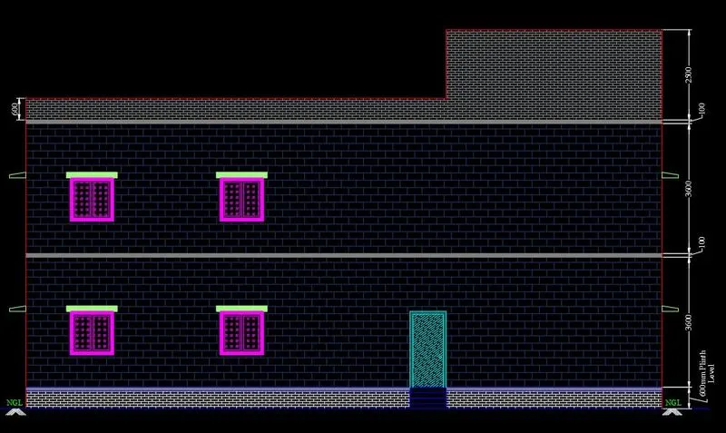
- Now type 'O' to invoke the offset tool and specify the offset distance as 600.
- Select the horizontal NGL horizontal line and offset it upward. This is the plinth level.
- type 'O' to invoke the offset tool and specify the offset distance as 100.
- Select the horizontal Plinth horizontal line and offset it downward. This is the base PCC with damp proof course.
- Now type 'O' to invoke the offset tool and specify the offset distance as 900.
- Select the horizontal Plinth horizontal line and offset it upward. This is the Sill level.
- Now type 'O' to invoke the offset tool and specify the offset distance as 2100.
- Select the horizontal Plinth horizontal line and offset it upward. This is the Lintel level.
- Now type 'O' to invoke the offset tool and specify the offset distance as 3600.
- Select the horizontal Plinth horizontal line and offset it upward. This is the Bottom level of the Roof slab.
- Now type 'O' to invoke the offset tool and specify the offset distance as 100.
- Select the horizontal line which is the bottom level of the roof slab and offset it upward. This is the Top level of the roof slab.
- Using similar procedure by using offset tool, draw the First floor also.
- Now using trim tool, trim off the unwanted lines.
- Also using Erase tool erase the unwanted lines.
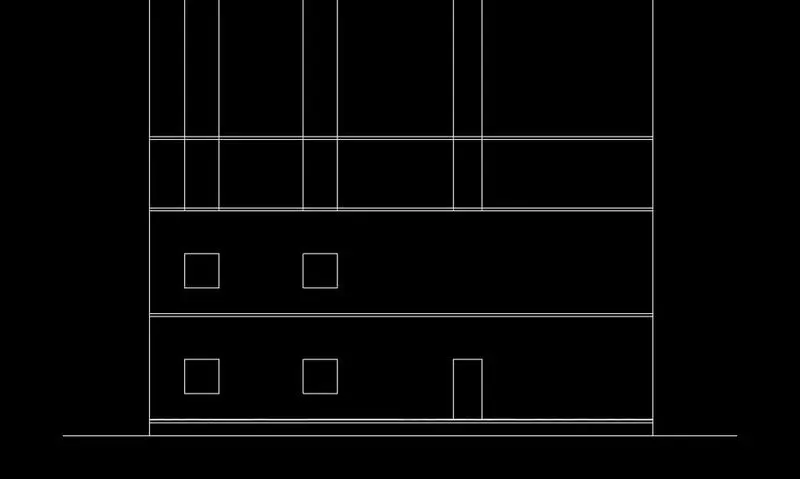
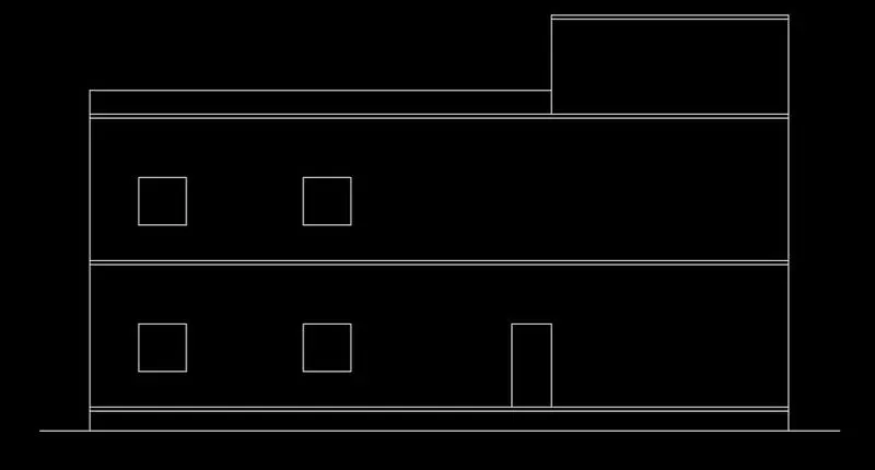
- Now assign the objects in the drawing to its respective layers.
- Draw the window and door panel using offset tool.
- Type 'hatch' and select 'Brick' pattern and hatch the wall part.
- Also hatch the windows and door frame using Solid hatch.
- Use Gost glass hatch in the windows panel and Gost wooden in the door panel.
- Draw the chajja using line tool and offset tool and hatch it using solid pattern.
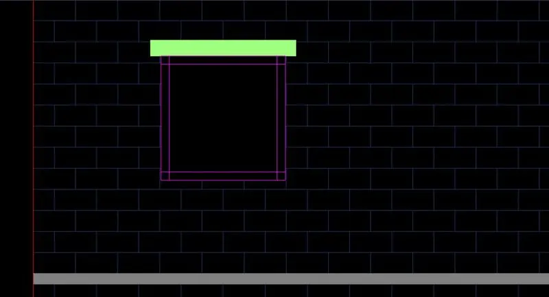
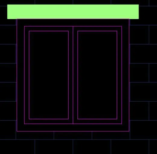
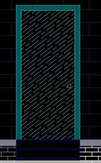
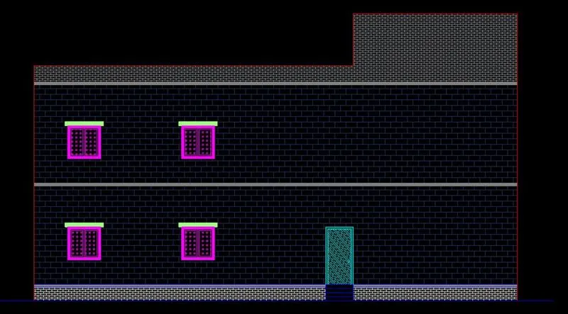
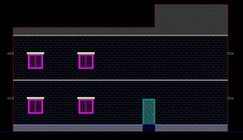
- Now using mtext tool assign the texts wherever required.
- Use dimlin command to assign the dimensions.
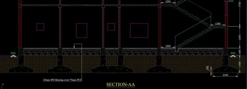
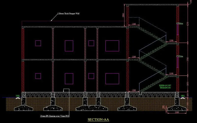
PART D: Preparing the Section A-A:
- Type 'XL' and choose Vertical lines.
- Select all the points of the walls for the plan.

- Type 'XL' and choose horizontal lines.
- Select all the elevation points in the Elevation drawing.
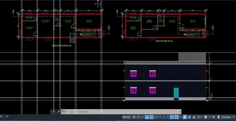
- Type 'Tr' and trim off the unwanted lines.
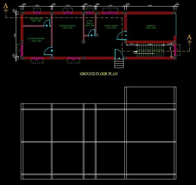
- Type 'XL' and choose vertical lines.
- Select the Column points of the plan.
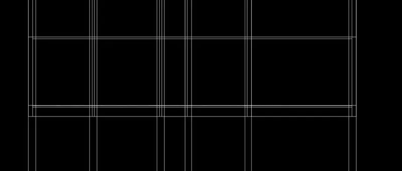
- Using Trim tool trim off the unwated lines.
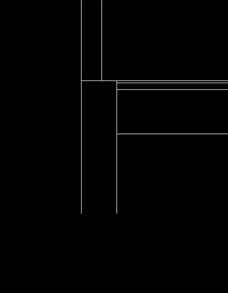
- Type 'L' and choosing the first point as the point of the plinth level and column construction line intersection draw a line downward at a distance 1500.
- Using copy tool paste the line created to the other intersection point.
- Type 'L' and specify first point anywhere in the sceen.
- Using ortho mode draw a line in x direction taking distance as 2100.
- Type 'O' and specify the offset distance as 300.
- Offset the horizontal line upward.
- Offset the horisontal line upward again.
- Now using line tool draw a Line with distance 500
- Using move tool move the line to mid point of the previous line and at a distance of 300 from the last top horizontal line.
- Now using move tool move the entire object and set it to the required position.
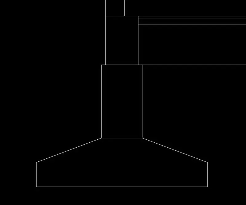
- Copy this footing section drawing and paste it in the required positions.
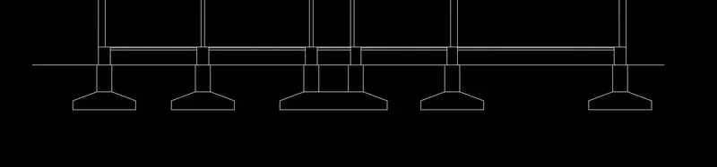
- Using Line tool and offset tool draw the beam section at an offset of 250 from the top of th floor slab.
- Using Trim tool trim off the unwanted lines.

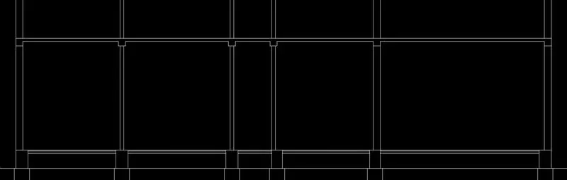
- Using Copy tool copy the whole beam object lines and paste it to first floor in the required position.
- Using Trim tool trim off the unwanted lines.
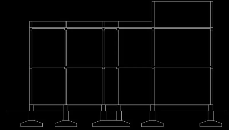
- Now assign the objects of the drawing to the respective layers.
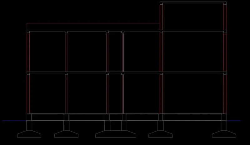
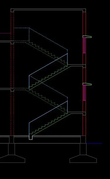
- Type 'XL' and select vertical lines.
- Select the staircase points in the Plan layout.
- Using line tool draw a line with distance 1200 by specifying first point as the top of the plinth beam.
- Using offset tool offset the drawn line at a distance 1850 upward.
- Now Using line tool draw Rise at a distance 142.307mm and Tread at a distance 250mm (draw it in the downward direction)
- Select all the steps drawn and press 'J' to join.
- Now select all the Steps and type 'mi' and select a point in the left side and click in the upward direction.
- Select the mirrored object and type 'm' to move and then select the base point as the end point of the object and then move it to the required position.
- Draw the stair slab using line tool and offset tool. Offset the line at a distance 125.
- Use 'Ex' command to extend the line wherever required.
- Use trim tool to trim off the unwanted lines.
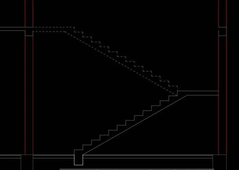
- Using Copy tool copy the drawn object and paste it in the first floor area.
- Also draw the handrail using line tool.
- Use trim command to trim off the unwanted lines.
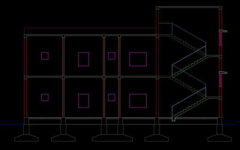
- Type 'XL' and select vertical lines and select the points on the window and ventilators in the plan layout
- Using line tool and offset tool draw the windows and ventilators in the section drawing.
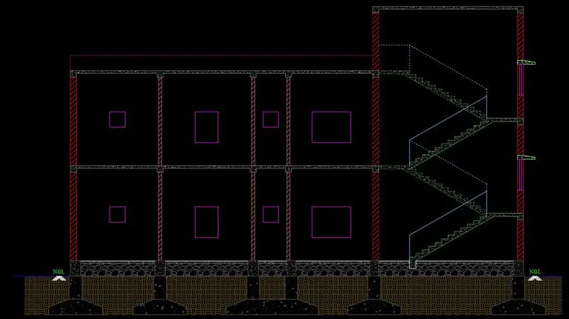
- Type 'H' and select Ar-conc and hatch all the concrete areas. Adjust scale as required.
- Similarly hatch all the other objects using Hatch tool.
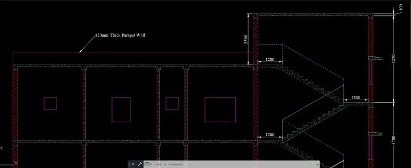
- Using Mtext command assign texts wherever required.
- Also using dimlin command assign dimension. We can use Dimcontinue for quick dimensioning.
- Using Multileader tool assign annotations wherever required.
2) STRUCTURAL DRAWING:-
PART A: Column Layout Plan:
- To draw the column layout plan we can do it by two method. First is by copying the Ground Floor plan and using centerline method or second is by creating a new drawing file and taking the refrence by 'xref' tool.
- I am doing it by simple copying method using Copy tool.
- Type 'Co' to invoke copy tool and select the entire object of the Ground Floor Plan.
- Select any basepoint and paste it somewhere in the drawing space.
- Now delete all the objects excluding the columns which were already in the ground floor plan. We can do it by selecting the objects and pressing E for erase.

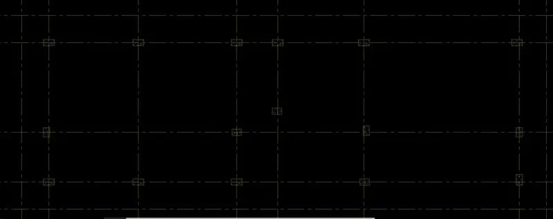
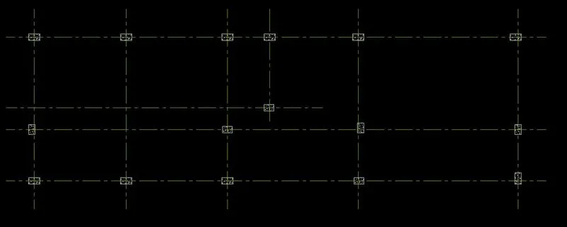
- From layer properties choose grid lines as current layer.
- Also Change the line type to Center and adjust the transparency and scale if needed.
- Type 'XL' for Construction lines and draw centerlines crossing all columns vertically and horizontally.
- Type 'O' for offset tool and specify the offset distance as 1000.
- Click on the extreme horizontal and vertical lines and offset them outward.
- Now using trim tool, trim off the unwanted lines.
- Now delete the offsetted line.
- Using Circle tool draw a circle of radius 300mm.
- Type 'attdef' to define attribute.
- Define the tag, prompt and default number.
- Select justification to center.
- Now place the text in the center of the circle.
- Type 'B' to create blocks.
- Pick a Quad point of the circle and select the object and press OK.
- Type 'I' to insert the blocks created.
- Click on the block and set it on the grid lines.
- Type 'Co' for copy tool and copy the block and paste them in other grid lines.
- Type 'Attedit' and then edit the texts.
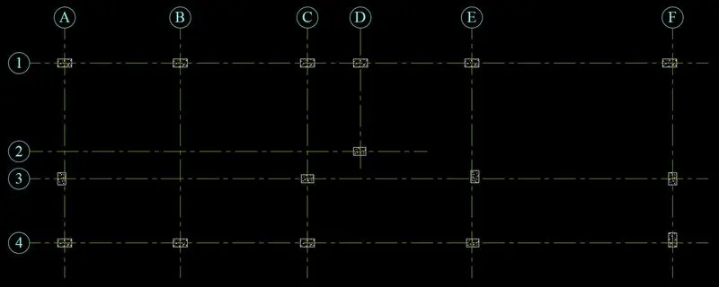
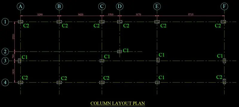
- Now using mtext command name all the columns.
- C1=230x350 and C2=230x400
- Also assign center to center distance of the columns using dimlin command.
PART B: Beam Layout Plan:
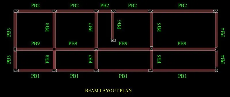
- Type 'Co' and select whole objects of column layout plan and paste it beneath the column layout plan.
- Delete all the objects except the columns.
- Using Line tool draw lines along the column vertically and horizontally.
- Using trim tool trim off the unwanted lines.
- Use hatch to hatch the beam using solid pattern.
- Using mtext command name all the beams.
PART C: Footing Layout Plan:
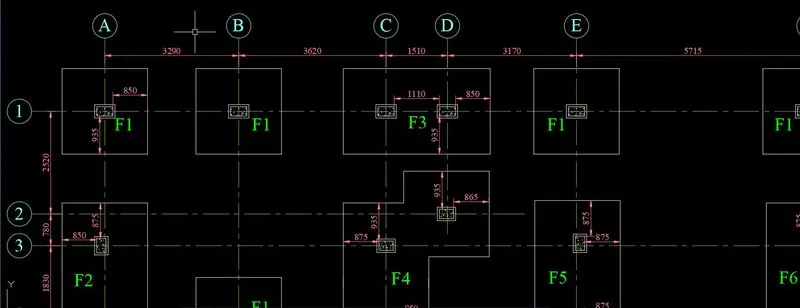
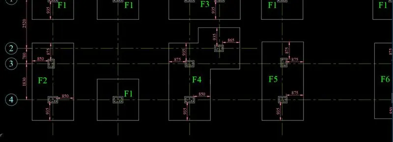
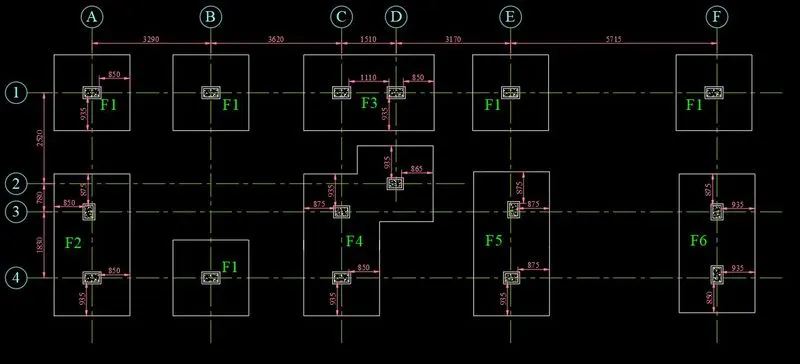
- Type 'Co' and select whole objects of column layout plan and paste it in the left side of the column layout plan.
- Delete all the objects except the columns and grid lines.
- Type 'Rec' to invoke rectangle tool click in the screen to specify the first point.
- Type @2100,2100 to specify the second point.
- Make sure the geometric center is truned on in ortho option.
- Now type 'Co' and select the rectangle drawn and select the base point as the geometric center of the rectangle.
- Now paste it in the geometric center of the columns.
- Using trim tool trim off the unwanted lines.
- Type 'O' for offset tool and specify the offset distance as 50.
- Select the columns and offset them outward. This is the Pedestal.
- Using mtext command name the footings.
- Using dimlin command assign dimensions wherever required.
RESULT:
- Check all the drawings and do necessary corrections if needed.
1) Architectural Drawings:
2) Structural Drawings: