Creation of geometries by Coordinate system methods using AutoCad
AIM: To create the geometries of figure P1 using all the coordinates system methods in AutoCAD.
INTRODUCTION:
- AutoCAD is a commercial computer-aided design (CAD) and drafting software application. Developed and marketed by Autodesk. AutoCAD was first released in December 1982 as a desktop app running on microcomputers with internal graphics controllers.
In the follwing problem we are using all the coordinates system. The coordinates systems are as follows:
i) Absoulte Coordinate System
ii) Relative Rectangular Coordinate System
iii) Relative Polar Coordinate System
iv) Direct distance entry
PROCEDURE:
Step 1: Open AutoCAD by clicking on the AutoCAD icon on the Desktop
Step 2: Start a new project by clicking Ctrl + N on the keyboard. A "Create new drawing" dialogue box will appear.
Step 3: Choose Imperial Template and Decimal units
Step 4: Commands used for different coordinate system are as follows:
i) Absolute Coordinate System:
- Choose the line tool by typing the command L or Line.
- Specify first point: 2,1
- Specify next point or [Undo]: 8,1
- Specify next point or [Undo]: 8,2
- Specify next point or [Close/Undo]: 3,2
- Specify next point or [Close/Undo]: 3,6
- Specify next point or [Close/Undo]: 8,6
- Specify next point or [Close/Undo]: 8,7
- Specify next point or [Close/Undo]: 2,7
- Specify next point or [Close/Undo]: close
- Type command "save". A "Save drawing as" dialogue box will appear. Choose the directory and file name and click the save button.
ii) Relative Recatngular Coordinate System:
- Choose the line tool by typing the command L or Line.
- Specify first point: 2,1
- Specify next point or [Undo]: @6,0
- Specify next point or [Undo]: @0,1
- Specify next point or [Close/Undo]: @-5,0
- Specify next point or [Close/Undo]: @0,4
- Specify next point or [Close/Undo]: @5,0
- Specify next point or [Close/Undo]: @0,1
- Specify next point or [Close/Undo]: @-6,0
- Specify next point or [Close/Undo]: close
- Type command "save". A "Save drawing as" dialogue box will appear. Choose the directory and file name and click the save button.
iii) Relative Polar Coordinate System:
- Choose the line tool by typing the command L or Line.
- Specify first point: 2,1
- Specify next point or [Undo]: @6<0
- Specify next point or [Undo]: @1<90
- Specify next point or [Close/Undo]: @5<180
- Specify next point or [Close/Undo]: @4<90
- Specify next point or [Close/Undo]: @5<0
- Specify next point or [Close/Undo]: @1<90
- Specify next point or [Close/Undo]: @6<180
- Specify next point or [Close/Undo]: close
- Type command "save". A "Save drawing as" dialogue box will appear. Choose the directory and file name and click the save button.
iv) Direct Distance Entry:
- Choose the line tool by typing the command L or Line.
- Specify first point: 2,1
- Specify next point or [Undo]: Position the cursor and enter distance 6
- Specify next point or [Undo]: Position the cursor and enter distance 1
- Specify next point or [Close/Undo]: Position the cursor and enter distance 5
- Specify next point or [Close/Undo]: Position the cursor and enter distance 4
- Specify next point or [Close/Undo]: Position the cursor and enter distance 5
- Specify next point or [Close/Undo]: Position the cursor and enter distance 1
- Specify next point or [Close/Undo]: Position the cursor and enter distance 6
- Specify next point or [Close/Undo]: close
- Type command "save". A "Save drawing as" dialogue box will appear. Choose the directory and file name and click the save button.
RESULT: The final result will be same for all the procedure mentioned above. And the result figure is given below:
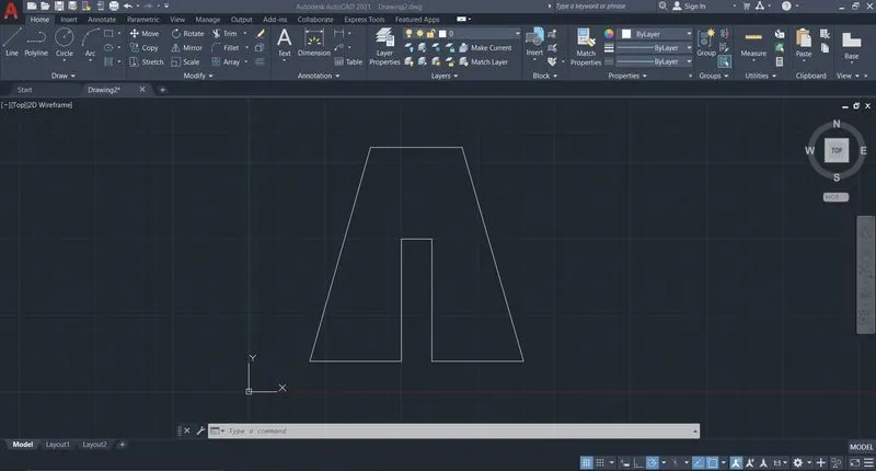
AIM: To create the geometries of figure P2 using all the coordinates system methods in AutoCAD.
INTRODUCTION:
- AutoCAD is a commercial computer-aided design (CAD) and drafting software application. Developed and marketed by Autodesk. AutoCAD was first released in December 1982 as a desktop app running on microcomputers with internal graphics controllers.
In the follwing problem we are using all the coordinates system. The coordinates systems are as follows:
i) Absoulte Coordinate System
ii) Relative Rectangular Coordinate System
iii) Relative Polar Coordinate System
iv) Direct distance entry
PROCEDURE:
Step 1: Open AutoCAD by clicking on the AutoCAD icon on the Desktop
Step 2: Start a new project by clicking Ctrl + N on the keyboard. A "Create new drawing" dialogue box will appear.
Step 3: Choose Imperial Template and Decimal units
Step 4: Commands used for different coordinate system are as follows:
i) Absolute Coordinate System:
- Choose the line tool by typing the command L or Line.
- Specify first point: 2,1
- Specify next point or [Undo]: 5,1
- Specify next point or [Undo]: 5,5
- Specify next point or [Close/Undo]:6,5
- Specify next point or [Close/Undo]: 6,1
- Specify next point or [Close/Undo]: 9,1
- Specify next point or [Close/Undo]: 7,8
- Specify next point or [Close/Undo]: 4,8
- Specify next point or [Close/Undo]: close
- Type command "save". A "Save drawing as" dialogue box will appear. Choose the directory and file name and click the save button.
ii) Relative Recatngular Coordinate System:
- Choose the line tool by typing the command L or Line.
- Specify first point: 2,1
- Specify next point or [Undo]: @3,0
- Specify next point or [Undo]: @0,4
- Specify next point or [Close/Undo]: @1,0
- Specify next point or [Close/Undo]: @0,-4
- Specify next point or [Close/Undo]: @3,0
- Specify next point or [Close/Undo]: @-2,7
- Specify next point or [Close/Undo]: @-3,0
- Specify next point or [Close/Undo]: close
- Type command "save". A "Save drawing as" dialogue box will appear. Choose the directory and file name and click the save button.
iii) Relative Polar Coordinate System:
- Choose the line tool by typing the command L or Line.
- Specify first point: 2,1
- Specify next point or [Undo]: @3<0
- Specify next point or [Undo]: @4<90
- Specify next point or [Close/Undo]: @1<0
- Specify next point or [Close/Undo]: @4<270
- Specify next point or [Close/Undo]: @3<0
- Specify next point or [Close/Undo]: @7.28<105.9454
- Specify next point or [Close/Undo]: @3<180
- Specify next point or [Close/Undo]: close
- Type command "save". A "Save drawing as" dialogue box will appear. Choose the directory and file name and click the save button.
iv) Direct Distance Entry:
- Choose the line tool by typing the command L or Line.
- Specify first point: 2,1
- Specify next point or [Undo]: Position the cursor and enter distance 3
- Specify next point or [Undo]: Position the cursor and enter distance 4
- Specify next point or [Close/Undo]: Position the cursor and enter distance 1
- Specify next point or [Close/Undo]: Position the cursor and enter distance 4
- Specify next point or [Close/Undo]: Position the cursor and enter distance 3
- Specify next point or [Close/Undo]: Position the cursor and enter distance 7.28
- Specify next point or [Close/Undo]: Position the cursor and enter distance 3
- Specify next point or [Close/Undo]: close
- Type command "save". A "Save drawing as" dialogue box will appear. Choose the directory and file name and click the save button.
RESULT: The final result will be same for all the procedure mentioned above. And the result figure is given below:
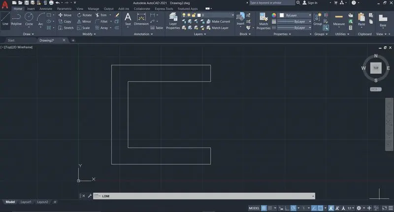
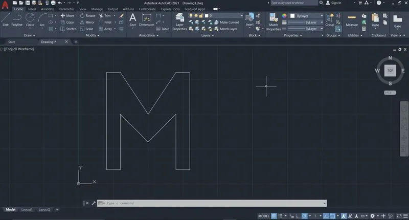
AIM: To create the geometries of figure P4 using any coordinates system methods in AutoCAD.
INTRODUCTION:
- AutoCAD is a commercial computer-aided design (CAD) and drafting software application. Developed and marketed by Autodesk. AutoCAD was first released in December 1982 as a desktop app running on microcomputers with internal graphics controllers.
The coordinates systems used in AutoCAD are as follows:
i) Absoulte Coordinate System
ii) Relative Rectangular Coordinate System
iii) Relative Polar Coordinate System
iv) Direct distance entry
- For the following figure I will be using Relative Rectangular Coordinate System.
PROCEDURE:
Step 1: Open AutoCAD by clicking on the AutoCAD icon on the Desktop
Step 2: Start a new project by clicking Ctrl + N on the keyboard. A "Create new drawing" dialogue box will appear.
Step 3: Choose Imperial Template and Decimal units
Step 4: Commands used are as follows:
- Choose the line tool by typing the command L or Line.
- Specify first point: 2,1
- Specify next point or [Undo]: @1,0
- Specify next point or [Undo]: @0,4
- Specify next point or [Close/Undo]: @2,-2
- Specify next point or [Close/Undo]: @2,2
- Specify next point or [Close/Undo]: @0,-4
- Specify next point or [Close/Undo]: @1,0
- Specify next point or [Close/Undo]: @0,7
- Specify next point or [Close/Undo]: @-1,0
- Specify next point or [Close/Undo]: @-2,-3
- Specify next point or [Close/Undo]: @-2,3
- Specify next point or [Close/Undo]: @-1,0
- Specify next point or [Close/Undo]: c
- Type command "save". A "Save drawing as" dialogue box will appear. Choose the directory and file name and click the save button.
RESULT: The resultant figure is given below:
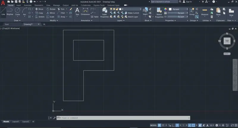
AIM: To create the geometries of figure P5 using any coordinates system methods in AutoCAD.
INTRODUCTION:
- AutoCAD is a commercial computer-aided design (CAD) and drafting software application. Developed and marketed by Autodesk. AutoCAD was first released in December 1982 as a desktop app running on microcomputers with internal graphics controllers.
The coordinates systems used in AutoCAD are as follows:
i) Absoulte Coordinate System
ii) Relative Rectangular Coordinate System
iii) Relative Polar Coordinate System
iv) Direct distance entry
- For the following figure I will be using Relative Rectangular Coordinate System.
PROCEDURE:
Step 1: Open AutoCAD by clicking on the AutoCAD icon on the Desktop
Step 2: Start a new project by clicking Ctrl + N on the keyboard. A "Create new drawing" dialogue box will appear.
Step 3: Choose Imperial Template and Decimal units
Step 4: Commands used are as follows:
- Choose the line tool by typing the command L or Line.
- Specify first point: 2,1
- Specify next point or [Undo]: @1,0
- Specify next point or [Undo]: @0,7
- Specify next point or [Close/Undo]: @5,0
- Specify next point or [Close/Undo]: @0,-6
- Specify next point or [Close/Undo]: @-3,0
- Specify next point or [Close/Undo]: @0,-1
- Specify next point or [Close/Undo]: @4,0
- Specify next point or [Close/Undo]: @0,8
- Specify next point or [Close/Undo]: @-7,0
- Specify next point or [Close/Undo]: @c
- Type command "save". A "Save drawing as" dialogue box will appear. Choose the directory and file name and click the save button.
RESULT: The resultant figure is given below:
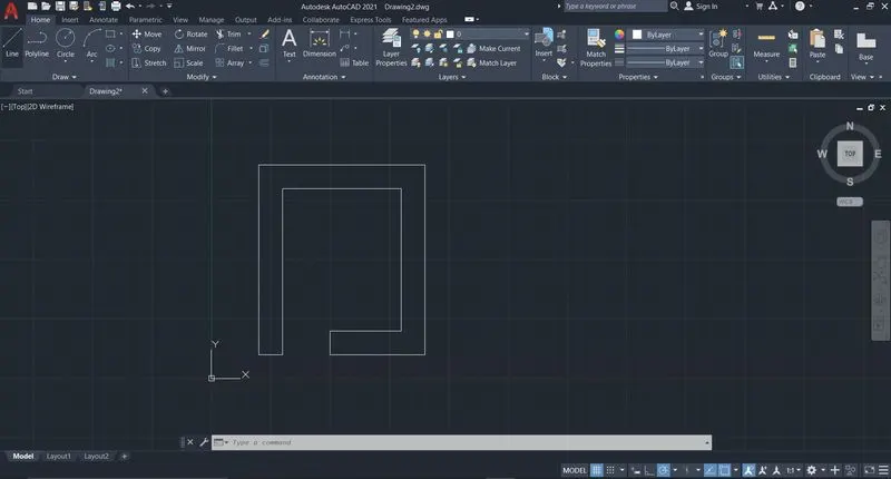
AIM: To create the geometries of figure P7 using any coordinates system methods in AutoCAD.
INTRODUCTION:
- AutoCAD is a commercial computer-aided design (CAD) and drafting software application. Developed and marketed by Autodesk. AutoCAD was first released in December 1982 as a desktop app running on microcomputers with internal graphics controllers.
The coordinates systems used in AutoCAD are as follows:
i) Absoulte Coordinate System
ii) Relative Rectangular Coordinate System
iii) Relative Polar Coordinate System
iv) Direct distance entry
- For the following figure I will be using Relative Rectangular Coordinate System.
PROCEDURE:
Step 1: Open AutoCAD by clicking on the AutoCAD icon on the Desktop
Step 2: Start a new project by clicking Ctrl + N on the keyboard. A "Create new drawing" dialogue box will appear.
Step 3: Choose Imperial Template and Decimal units
Step 4: Commands used are as follows:
- Choose the line tool by typing the command L or Line.
- Specify first point: 2,1
- Specify next point or [Undo]: @8,0
- Specify next point or [Undo]: @0,6
- Specify next point or [Close/Undo]: @-8,0
- Specify next point or [Close/Undo]: c
- Choose the line tool by typing the command L or Line.
- Specify first point: 3,2
- Specify next point or [Undo]: @2,0
- Specify next point or [Undo]: @0,3
- Specify next point or [Close/Undo]: @-2,0
- Specify next point or [Close/Undo]: c
- Choose the line tool by typing the command L or Line.
- Specify first point: 6,2
- Specify next point or [Undo]: @2,0
- Specify next point or [Undo]: @0,3
- Specify next point or [Close/Undo]: @-2,0
- Specify next point or [Close/Undo]: c
- Type command "save". A "Save drawing as" dialogue box will appear. Choose the directory and file name and click the save button.
RESULT: The resultant figure is given below:
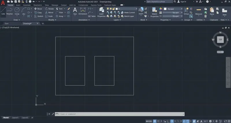
AIM: To create the geometries of figure P8 using any coordinates system methods in AutoCAD.
INTRODUCTION:
- AutoCAD is a commercial computer-aided design (CAD) and drafting software application. Developed and marketed by Autodesk. AutoCAD was first released in December 1982 as a desktop app running on microcomputers with internal graphics controllers.
The coordinates systems used in AutoCAD are as follows:
i) Absoulte Coordinate System
ii) Relative Rectangular Coordinate System
iii) Relative Polar Coordinate System
iv) Direct distance entry
- For the following figure I will be using Direct distance entry.
PROCEDURE:
Step 1: Open AutoCAD by clicking on the AutoCAD icon on the Desktop
Step 2: Start a new project by clicking Ctrl + N on the keyboard. A "Create new drawing" dialogue box will appear.
Step 3: Choose Imperial Template and Decimal units
Step 4: Commands used are as follows:
- Choose the line tool by typing the command L or Line.
- Specify first point: 0,0
- Specify next point or [Undo]: Position the cursor and enter distance 10
- Specify next point or [Undo]: Position the cursor and enter distance 2
- Specify next point or [Close/Undo]: Position the cursor and enter distance 4
- Specify next point or [Close/Undo]: Position the cursor and enter distance 4
- Specify next point or [Close/Undo]: Position the cursor and enter distance 3
- Specify next point or [Close/Undo]: Position the cursor and enter distance 2
- Specify next point or [Close/Undo]: Position the cursor and enter distance 8
- Specify next point or [Close/Undo]: Position the cursor and enter distance 2
- Specify next point or [Close/Undo]: Position the cursor and enter distance 3
- Specify next point or [Close/Undo]: Position the cursor and enter distance 4
- Specify next point or [Close/Undo]: Position the cursor and enter distance 4
- Specify next point or [Close/Undo]: close
- Type command "save". A "Save drawing as" dialogue box will appear. Choose the directory and file name and click the save button.
RESULT: The resultant figure is given below:
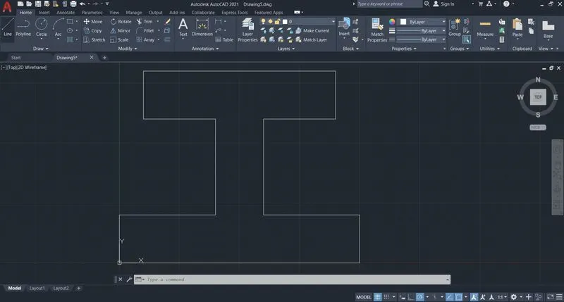
AIM: To create the geometries of figure P9 using any coordinates system methods in AutoCAD.
INTRODUCTION:
- AutoCAD is a commercial computer-aided design (CAD) and drafting software application. Developed and marketed by Autodesk. AutoCAD was first released in December 1982 as a desktop app running on microcomputers with internal graphics controllers.
The coordinates systems used in AutoCAD are as follows:
i) Absoulte Coordinate System
ii) Relative Rectangular Coordinate System
iii) Relative Polar Coordinate System
iv) Direct distance entry
PROCEDURE:
Step 1: Open AutoCAD by clicking on the AutoCAD icon on the Desktop
Step 2: Start a new project by clicking Ctrl + N on the keyboard. A "Create new drawing" dialogue box will appear.
Step 3: Choose Imperial Template and Decimal units
Step 4: Commands used are as follows:
- Choose the line tool by typing the command L or Line.
- Specify first point: 1,1
- Specify next point or [Undo]: Position the cursor and enter distance 5
- Specify next point or [Undo]: Position the cursor and enter distance 2
- Specify next point or [Close/Undo]: Position the cursor and enter distance 3
- Specify next point or [Close/Undo]: Position the cursor and enter distance 1
- Specify next point or [Close/Undo]: Position the cursor and enter distance 1
- Specify next point or [Close/Undo]: Position the cursor and enter distance 2
- Specify next point or [Close/Undo]: Position the cursor and enter distance 3
- Specify next point or [Close/Undo]: Position the cursor and enter distance 2
- Specify next point or [Close/Undo]: @-4,2
- Specify next point or [Close/Undo]: close
- Type command "save". A "Save drawing as" dialogue box will appear. Choose the directory and file name and click the save button.
RESULT: The resultant figure is given below:
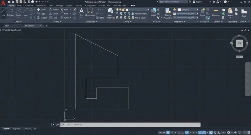
AIM: To create the geometries of figure P10 using any coordinates system methods in AutoCAD.
INTRODUCTION:
- AutoCAD is a commercial computer-aided design (CAD) and drafting software application. Developed and marketed by Autodesk. AutoCAD was first released in December 1982 as a desktop app running on microcomputers with internal graphics controllers.
The coordinates systems used in AutoCAD are as follows:
i) Absoulte Coordinate System
ii) Relative Rectangular Coordinate System
iii) Relative Polar Coordinate System
iv) Direct distance entry
PROCEDURE:
Step 1: Open AutoCAD by clicking on the AutoCAD icon on the Desktop
Step 2: Start a new project by clicking Ctrl + N on the keyboard. A "Create new drawing" dialogue box will appear.
Step 3: Choose Imperial Template and Decimal units
Step 4: Commands used are as follows:
- Choose the line tool by typing the command L or Line.
- Specify first point: 1,1
- Specify next point or [Undo]: Position the cursor and enter distance 2
- Specify next point or [Undo]: Position the cursor and enter distance 3
- Specify next point or [Close/Undo]: Position the cursor and enter distance 3
- Specify next point or [Close/Undo]: Position the cursor and enter distance 4
- Specify next point or [Close/Undo]: Position the cursor and enter distance 5
- Specify next point or [Close/Undo]: c
- Choose the line tool by typing the command L or Line.
- Specify first point: 2,5
- Specify next point or [Undo]: Position the cursor and enter distance 3
- Specify next point or [Undo]: Position the cursor and enter distance 2
- Specify next point or [Close/Undo]: Position the cursor and enter distance 3
- Specify next point or [Close/Undo]: close
- Type command "save". A "Save drawing as" dialogue box will appear. Choose the directory and file name and click the save button.
RESULT: The resultant figure is given below:
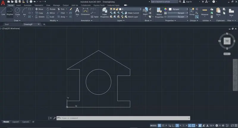
AIM: To create the geometries of figure Profile-Wood using any coordinates system methods in AutoCAD.
INTRODUCTION:
- AutoCAD is a commercial computer-aided design (CAD) and drafting software application. Developed and marketed by Autodesk. AutoCAD was first released in December 1982 as a desktop app running on microcomputers with internal graphics controllers.
The coordinates systems used in AutoCAD are as follows:
i) Absoulte Coordinate System
ii) Relative Rectangular Coordinate System
iii) Relative Polar Coordinate System
iv) Direct distance entry
PROCEDURE:
Step 1: Open AutoCAD by clicking on the AutoCAD icon on the Desktop
Step 2: Start a new project by clicking Ctrl + N on the keyboard. A "Create new drawing" dialogue box will appear.
Step 3: Choose Imperial Template and Decimal units
Step 4: Commands used are as follows:
- Choose the line tool by typing the command L or Line.
- Specify first point: 0,0
- Specify next point or [Undo]: Position the cursor and enter distance 10
- Specify next point or [Undo]: Position the cursor and enter distance 1
- Specify next point or [Close/Undo]: Position the cursor and enter distance 2
- Specify next point or [Close/Undo]: Position the cursor and enter distance 4
- Specify next point or [Close/Undo]: Position the cursor and enter distance 2
- Specify next point or [Close/Undo]: Position the cursor and enter distance 1
- Specify next point or [Close/Undo]: @5.831<149.036
- Specify next point or [Close/Undo]: @5.831<210.964
- Specify next point or [Close/Undo]: Position the cursor and enter distance 2
- Specify next point or [Close/Undo]: Position the cursor and enter distance 5
- Specify next point or [Close/Undo]: Position the cursor and enter distance 2
- Specify next point or [Close/Undo]: close
- Choose the circle tool by typing the command circle.
- CIRCLE Specify center point for circle or [3P 2P Ttr (tan tan radius)]: 5,4
- CIRCLE Specify radius of circle or [Diameter]: 2
- Type command "save". A "Save drawing as" dialogue box will appear. Choose the directory and file name and click the save button.
RESULT: The resultant figure is given below:
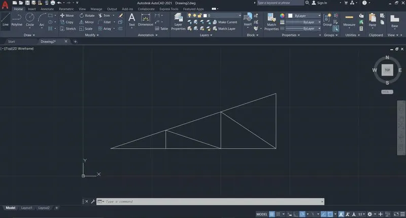
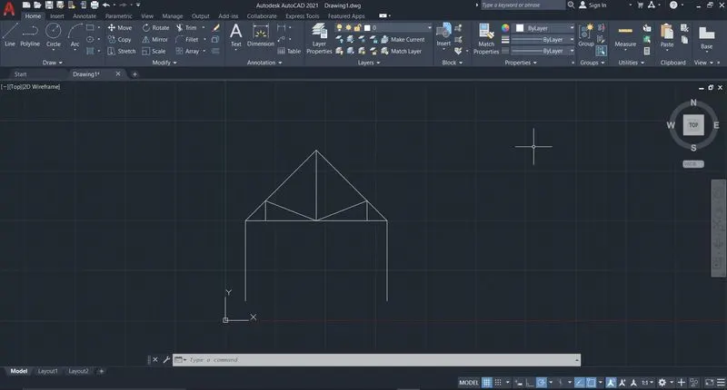
AIM: To create the geometries of figure Queen Post Truss using any coordinates system methods in AutoCAD.
INTRODUCTION:
- AutoCAD is a commercial computer-aided design (CAD) and drafting software application. Developed and marketed by Autodesk. AutoCAD was first released in December 1982 as a desktop app running on microcomputers with internal graphics controllers.
The coordinates systems used in AutoCAD are as follows:
i) Absoulte Coordinate System
ii) Relative Rectangular Coordinate System
iii) Relative Polar Coordinate System
iv) Direct distance entry
PROCEDURE:
Step 1: Open AutoCAD by clicking on the AutoCAD icon on the Desktop
Step 2: Start a new project by clicking Ctrl + N on the keyboard. A "Create new drawing" dialogue box will appear.
Step 3: Choose Imperial Template and Decimal units
Step 4: Commands used are as follows:
- Choose the line tool by typing the command L or Line.
- Specify first point: 1,1
- Specify next point or [Undo]: Position the cursor and enter distance 4
- Specify next point or [Undo]: @5<45
- Specify next point or [Close/Undo]: @5<315
- Specify next point or [Close/Undo]: Position the cursor and enter distance 4
- Specify next point or [Close/Undo]: *cancel*
- Choose the line tool by typing the command L or Line.
- Specify first point: 1,5
- Specify next point or [Undo]: Position the cursor and enter distance 7.072
- Specify next point or [Undo]: *cancel*
- Choose the line tool by typing the command L or Line.
- Specify first point: 4.536,5
- Specify next point or [Undo]: Position the cursor and enter distance 3.536
- Specify next point or [Undo]: *cancel*
- Choose the line tool by typing the command L or Line.
- Specify first point: 2,5
- Specify next point or [Undo]: @0,1
- Specify next point or [Undo]: @2.536,-1
- Specify next point or [Close/Undo]: @2.536,1
- Specify next point or [Close/Undo]: @0,-1
- Specify next point or [Close/Undo]: *cancel*
- Type command "save". A "Save drawing as" dialogue box will appear. Choose the directory and file name and click the save button.
RESULT: The resultant figure is given below:
AIM: To create the geometries of figure Mono Pitch using any coordinates system methods in AutoCAD.
INTRODUCTION:
- AutoCAD is a commercial computer-aided design (CAD) and drafting software application. Developed and marketed by Autodesk. AutoCAD was first released in December 1982 as a desktop app running on microcomputers with internal graphics controllers.
The coordinates systems used in AutoCAD are as follows:
i) Absoulte Coordinate System
ii) Relative Rectangular Coordinate System
iii) Relative Polar Coordinate System
iv) Direct distance entry
PROCEDURE:
Step 1: Open AutoCAD by clicking on the AutoCAD icon on the Desktop
Step 2: Start a new project by clicking Ctrl + N on the keyboard. A "Create new drawing" dialogue box will appear.
Step 3: Choose Imperial Template and Decimal units
Step 4: Commands used are as follows:
- Choose the line tool by typing the command L or Line.
- Specify first point: 1,1
- Specify next point or [Undo]: @6,0
- Specify next point or [Undo]: @0,2
- Specify next point or [Close/Undo]: c
- Choose the line tool by typing the command L or Line.
- Specify first point: 3,1
- Specify next point or [Undo]: @0,0.667
- Specify next point or [Undo]: @2,-0.667
- Specify next point or [Close/Undo]: @0,1.333
- Specify next point or [Close/Undo]: @2,-1.333
- Specify next point or [Close/Undo]: *cancel*
- Type command "save". A "Save drawing as" dialogue box will appear. Choose the directory and file name and click the save button.
RESULT: The resultant figure is given below: