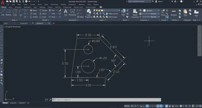
Drafting of various geometries using Chamfer, Fillet tool in AutoCad
AIM: Creating the first drawing using AutoCAD.
INTRODUCTION:
AutoCAD is a commercial computer-aided design (CAD) and drafting software application. Developed and marketed by Autodesk, AutoCAD was first released in December 1982 as a desktop app running on microcomputers with internal graphics controllers. Before AutoCAD was introduced, most commercial CAD programs ran on mainframe computers or minicomputers, with each CAD operator (user) working at a separate graphics terminal. AutoCAD is also available as mobile and web apps.
AutoCAD is used in industry, by architects, project managers, engineers, graphic designers, city planners and other professionals.
PROCEDURE:
Step 1: Open AutoCAD by clicking on the AutoCAD icon on the Desktop
Step 2: Start a new project by clicking Ctrl + N on the keyboard. A "Create new drawing" dialogue box will appear.
Step 3: Choose Imperial Template and Decimal units from advance option
Step 4: Commands used are as follows:
- Go to drafting settings by typing 'OS' in the command prompt and choose polar tracking at 45 degree.
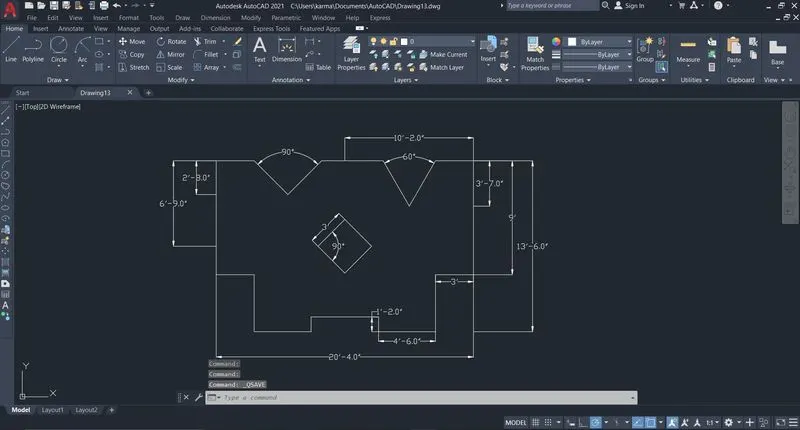
- Choose end point, mid point, center object snap from drafrting settings or status bar.
- In the command prompt type 'L' for Line tool
- Specify first point: Click anywhere in the screen
- Specify next point or [Undo]: Through polar tracking choose 0 degree and type 3
- Specify next point or [Undo]: Through polar tracking choose 45 degree and type 2.12
- Specify next point or [Close/Undo]: Through polar tracking choose 90 degree and type 2.83
- Specify next point or [Close/Undo]: Through polar tracking choose 180 degree and type 2
- Specify next point or [Close/Undo]: Type 'C' for closing the line
- In the command prompt type 'XL' for construction line
- Specify a point or [Hor/Ver/Ang/Bisect/Offset]: Type 'O' for Offset
- Specify offset distance or [Through] <2.5000>: Type 2.5
- Select a line object: Select the bottom line
- Specify side to offset: Choose the North side
- Select a line object: *Cancel*
- In the command prompt type 'XL' for construction line
- Specify a point or [Hor/Ver/Ang/Bisect/Offset]: Type 'O' for Offset
- Specify offset distance or [Through] <2.5000>: Type 1
- Select a line object: Select the bottom line
- Specify side to offset: Choose the North side
- Select a line object: *Cancel*
- In the command prompt type 'XL' for construction line
- Specify a point or [Hor/Ver/Ang/Bisect/Offset]: Type 'V' for Vertical construction line
- Specify through point: Choose the mid point of the bottom line and left click
- Specify through point: *Cancel*
- In the command prompt type 'C' for Circle tool
- Specify center point for circle or [3P/2P/Ttr (tan tan radius)]: Choose the bottom intersection point of the construction line as center of the circle
- Specify radius of circle or [Diameter]: Type 'D' for diameter
- Specify diameter of circle: Type 1.20
- In the command prompt type 'C' for Circle tool
- Specify center point for circle or [3P/2P/Ttr (tan tan radius)]: Choose the top intersection point of the construction line as center of the circle
- Specify radius of circle or [Diameter] <0.6000>: Type 'D' for diameter
- Specify diameter of circle <1.2000>: Type 0.80
- Now select the construction lines previously drawn and type 'E' in the command prompt to erase
- For Dimensions type command dimlin, dimang and dimdia in the command prompt.
Step 5: Type command "save". A "Save drawing as" dialogue box will appear. Choose the directory and file name and click the save button.
RESULT:
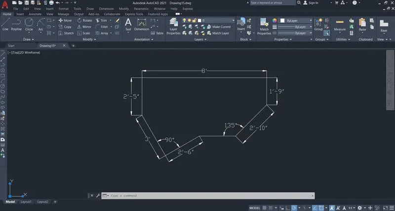
AIM: Creating the second drawing using AutoCAD.
INTRODUCTION:
AutoCAD is a commercial computer-aided design (CAD) and drafting software application. Developed and marketed by Autodesk, AutoCAD was first released in December 1982 as a desktop app running on microcomputers with internal graphics controllers. Before AutoCAD was introduced, most commercial CAD programs ran on mainframe computers or minicomputers, with each CAD operator (user) working at a separate graphics terminal. AutoCAD is also available as mobile and web apps.
AutoCAD is used in industry, by architects, project managers, engineers, graphic designers, city planners and other professionals.
PROCEDURE:
Step 1: Open AutoCAD by clicking on the AutoCAD icon on the Desktop
Step 2: Start a new project by clicking Ctrl + N on the keyboard. A "Create new drawing" dialogue box will appear.
Step 3: Choose Imperial Template and Architectural units from advance option
Step 4: Commands used are as follows:
- In the command prompt type 'PL' for PolyLine tool
- Specify first point: Click anywhere in the screen
- Make sure the polar tracking is set to 45 degree
- Specify next point at 90 degree 2'-5"
- Specify next point at 0 degree 8'
- Specify next point at 270 degree 1'-9"
- Specify next point at 0 degree 8'
- Specify next point at 225 degree 2'-10"
- Now draw a horizontal line at 180 degree
- Press Esc to cancel the polyline tool
- Now Type 'L' for line tool in the command prompt
- Specify first point by clicking anywhere in the screen
- Specify next point at 180 degree 2'-6"
- Specify next point at 90 degree 3'
- Press Esc to cancel the line tool
- Type 'M' to invoke move tool from the command prompt
- Select the top point of the right angle with sides 3' and 2'-6" which is previously drawn
- Select the first point of the of the drawing as the second point
- Type 'RO' for rotate tool form the command prompt
- Select the right angle drawn and press enter
- Select the top point of the right angle with sides 3' and 2'-6"
- Select dyanmic option and rotate to meet the nearest point the horizontal line drawn at last
- Type 'Tr' for trim tool from the command prompt
- Select and trim the unwanted lines
- For Dimensions type command dimlin, dimang in the command prompt.
Step 5: Type command "save". A "Save drawing as" dialogue box will appear. Choose the directory and file name and click the save button.
RESULT:
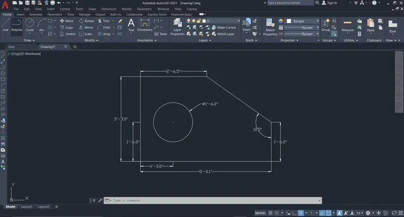
AIM: Creating the third drawing using AutoCAD.
INTRODUCTION:
AutoCAD is a commercial computer-aided design (CAD) and drafting software application. Developed and marketed by Autodesk, AutoCAD was first released in December 1982 as a desktop app running on microcomputers with internal graphics controllers. Before AutoCAD was introduced, most commercial CAD programs ran on mainframe computers or minicomputers, with each CAD operator (user) working at a separate graphics terminal. AutoCAD is also available as mobile and web apps.
AutoCAD is used in industry, by architects, project managers, engineers, graphic designers, city planners and other professionals.
PROCEDURE:
Step 1: Open AutoCAD by clicking on the AutoCAD icon on the Desktop
Step 2: Start a new project by clicking Ctrl + N on the keyboard. A "Create new drawing" dialogue box will appear.
Step 3: Choose Imperial Template and Engineering units from advance option
Step 4: Commands used are as follows:
- Go to drafting settings by typing 'OS' in the command prompt and choose polar tracking at 90 degree.
- In the command prompt type 'PL' for PolyLine tool
- Specify first point: Click anywhere in the screen
- Specify next point or [Arc/Halfwidth/Length/Undo/Width]: Through polar tracking choose 0 degree and type 5',0.1"
- Specify next point or [Arc/Close/Halfwidth/Length/Undo/Width]: Through polar tracking choose 90 degree and type 1'6.0"
- Specify next point or [Arc/Close/Halfwidth/Length/Undo/Width]: *Cancel*
- In the command prompt type 'PL' for PolyLine tool
- Specify first point: Click on the starting point
- Specify next point or [Arc/Halfwidth/Length/Undo/Width]: Through polar tracking choose 90 degree and type 3'3"
- Specify next point or [Arc/Close/Halfwidth/Length/Undo/Width]: Through polar tracking choose 0 degree and type 2'6.5"
- Specify next point or [Arc/Close/Halfwidth/Length/Undo/Width]: Join the line by clicking the end point
- Specify next point or [Arc/Close/Halfwidth/Length/Undo/Width]: *Cancel*
- In the command prompt type 'XL' for construction line
- Specify a point or [Hor/Ver/Ang/Bisect/Offset]: Type 'O' for Offset
- Specify offset distance or [Through] <0'-1">: Type 1'6"
- Select a line object: Select the bottom line
- Specify side to offset: Choose the North side
- Select a line object: *Cancel*
- In the command prompt type 'XL' for construction line
- Specify a point or [Hor/Ver/Ang/Bisect/Offset]: Type 'O' for Offset
- Specify offset distance or [Through] <0'-1">: Type 1'3"
- Select a line object: Select the left line
- Specify side to offset: Choose the east side
- Select a line object: *Cancel*
- In the command prompt type 'C' for Circle tool
- Specify center point for circle or [3P/2P/Ttr (tan tan radius)]: Choose the intersection point of the construction line as center of the circle
- Specify radius of circle or [Diameter]: Type 'D' for diameter
- Specify diameter of circle: Type 1'6"
- Now select the construction lines previously drawn and type 'E' in the command prompt to erase
- For Dimensions type command dimlin, dimang and dimdia in the command prompt.
Step 5: Type command "save". A "Save drawing as" dialogue box will appear. Choose the directory and file name and click the save button.
RESULT:
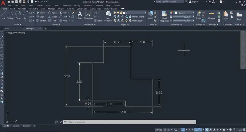
AIM: Creating the fourth drawing using AutoCAD.
INTRODUCTION:
AutoCAD is a commercial computer-aided design (CAD) and drafting software application. Developed and marketed by Autodesk, AutoCAD was first released in December 1982 as a desktop app running on microcomputers with internal graphics controllers. Before AutoCAD was introduced, most commercial CAD programs ran on mainframe computers or minicomputers, with each CAD operator (user) working at a separate graphics terminal. AutoCAD is also available as mobile and web apps.
AutoCAD is used in industry, by architects, project managers, engineers, graphic designers, city planners and other professionals.
PROCEDURE:
Step 1: Open AutoCAD by clicking on the AutoCAD icon on the Desktop
Step 2: Start a new project by clicking Ctrl + N on the keyboard. A "Create new drawing" dialogue box will appear.
Step 3: Choose Imperial Template and decimal units from advance option
Step 4: Commands used are as follows:
- Go to drafting settings by typing 'OS' in the command prompt and choose polar tracking at 90 degree.
- Choose end point, mid point, apparent intersection object snap from drafrting settings or status bar.
- In the command prompt type 'PL' for PolyLine tool
- Specify first point: Click anywhere in the screen
- Specify next point or [Arc/Halfwidth/Length/Undo/Width]: Through polar tracking choose 0 degree and type 3
- Specify next point or [Arc/Close/Halfwidth/Length/Undo/Width]: Through polar tracking choose 270 degree and type 0.50
- Specify next point or [Arc/Close/Halfwidth/Length/Undo/Width]: Through polar tracking choose 0 degree top and type 2.50
- Specify next point or [Arc/Close/Halfwidth/Length/Undo/Width]: Through polar tracking choose 90 degree and type 2.50
- Specify next point or [Arc/Close/Halfwidth/Length/Undo/Width]: Through polar tracking choose 180 degree and type 2
- Specify next point or [Arc/Close/Halfwidth/Length/Undo/Width]: Through polar tracking choose 90 degree and type 3
- Specify next point or [Arc/Close/Halfwidth/Length/Undo/Width]: Through polar tracking choose 180 degree and type 2.50
- Specify next point or [Arc/Close/Halfwidth/Length/Undo/Width]: Through polar tracking choose 270 degree and type 1.5
- Specify next point or [Arc/Close/Halfwidth/Length/Undo/Width]: Choose the intersection point of first and last point through apparent intersection lines
- Specify next point or [Arc/Close/Halfwidth/Length/Undo/Width]: Type 'C' for close
- For Dimensions type command dimlin in the command prompt.
Step 5: Type command "save". A "Save drawing as" dialogue box will appear. Choose the directory and file name and click the save button.
RESULT:
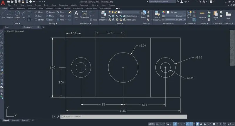
AIM: Creating the fifth drawing using AutoCAD.
INTRODUCTION:
AutoCAD is a commercial computer-aided design (CAD) and drafting software application. Developed and marketed by Autodesk, AutoCAD was first released in December 1982 as a desktop app running on microcomputers with internal graphics controllers. Before AutoCAD was introduced, most commercial CAD programs ran on mainframe computers or minicomputers, with each CAD operator (user) working at a separate graphics terminal. AutoCAD is also available as mobile and web apps.
AutoCAD is used in industry, by architects, project managers, engineers, graphic designers, city planners and other professionals.
PROCEDURE:
Step 1: Open AutoCAD by clicking on the AutoCAD icon on the Desktop
Step 2: Start a new project by clicking Ctrl + N on the keyboard. A "Create new drawing" dialogue box will appear.
Step 3: Choose Imperial Template and decimal units from advance option
Step 4: Commands used are as follows:
- Choose end point, mid point, center object snap from drafrting settings or status bar.
- In the command prompt type 'XL' for construction line
- Specify a point or [Hor/Ver/Ang/Bisect/Offset]: Type 'V' for Vertical construction line
- Specify through point: Click anywhere in the Screen
- Specify through point: *Cancel*
- In the command prompt type 'XL' for construction line
- Specify a point or [Hor/Ver/Ang/Bisect/Offset]: Type 'H' for horizontal construction line
- Specify through point: Click anywhere in the Screen
- Specify through point: *Cancel*
- In the command prompt type 'XL' for construction line
- Specify a point or [Hor/Ver/Ang/Bisect/Offset]: Type 'O' for Offset
- Specify offset distance or [Through] <2.5000>: Type 2.75
- Select a line object: Select the vertical construction line
- Specify side to offset: Choose the west side
- Select a line object: Select the vertical construction line
- Specify side to offset: Choose the east side
- Select a line object: *Cancel*
- In the command prompt type 'XL' for construction line
- Specify a point or [Hor/Ver/Ang/Bisect/Offset]: Type 'O' for Offset
- Specify offset distance or [Through] <2.5000>: Type 4.25
- Select a line object: Select the vertical construction line
- Specify side to offset: Choose the west side
- Select a line object: Select the vertical construction line
- Specify side to offset: Choose the east side
- Select a line object: *Cancel*
- In the command prompt type 'XL' for construction line
- Specify a point or [Hor/Ver/Ang/Bisect/Offset]: Type 'O' for Offset
- Specify offset distance or [Through] <2.5000>: Type 3
- Select a line object: Select the horizontal construction line
- Specify side to offset: Choose the north side
- Select a line object: Select the horizontal construction line
- Specify side to offset: Choose the south side
- Select a line object: *Cancel*
- In the command prompt type 'TR' for Trim tool
- Choose fence mode and select all the outer lines and trim it
- In the command prompt type 'C' for Circle tool
- Specify center point for circle or [3P/2P/Ttr (tan tan radius)]: Choose the mid intersection point of the construction line as center of the circle
- Specify radius of circle or [Diameter]: Type 'D' for diameter
- Specify diameter of circle: Type 3
- In the command prompt type 'C' for Circle tool
- Specify center point for circle or [3P/2P/Ttr (tan tan radius)]: Choose the right intersection point of the construction line as center of the circle
- Specify radius of circle or [Diameter]: Type 'D' for diameter
- Specify diameter of circle: Type 1
- In the command prompt type 'C' for Circle tool
- Specify center point for circle or [3P/2P/Ttr (tan tan radius)]: Choose the right intersection point of the construction line as center of the circle
- Specify radius of circle or [Diameter]: Type 'D' for diameter
- Specify diameter of circle: Type 2
- In the command prompt type 'CO' for Copy tool
- Select both circles from the right side and press enter
- Specify base point or [Displacement/mOde/Multiple] : Select the right intersection point of the construction line as the base point
- Specify second point or [Array] : Select the left intersection point of the construction line as the second point
- Now type 'E' in the command prompt for erase tool
- Select and erase the unwanter lines in the drawing.
- For Dimensions type command dimlin and dimdia in the command prompt.
Step 5: Type command "save". A "Save drawing as" dialogue box will appear. Choose the directory and file name and click the save button.
RESULT:
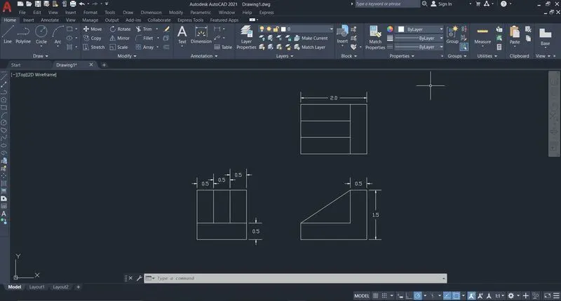
AIM: Creating the sixth drawing using AutoCAD.
INTRODUCTION:
AutoCAD is a commercial computer-aided design (CAD) and drafting software application. Developed and marketed by Autodesk, AutoCAD was first released in December 1982 as a desktop app running on microcomputers with internal graphics controllers. Before AutoCAD was introduced, most commercial CAD programs ran on mainframe computers or minicomputers, with each CAD operator (user) working at a separate graphics terminal. AutoCAD is also available as mobile and web apps.
AutoCAD is used in industry, by architects, project managers, engineers, graphic designers, city planners and other professionals.
PROCEDURE:
Step 1: Open AutoCAD by clicking on the AutoCAD icon on the Desktop
Step 2: Start a new project by clicking Ctrl + N on the keyboard. A "Create new drawing" dialogue box will appear.
Step 3: Choose Imperial Template and decimal units from advance option
Step 4: Commands used are as follows:
- Choose end point object snap from drafrting settings or status bar.
- In the command prompt type 'XL' for construction line
- Specify a point or [Hor/Ver/Ang/Bisect/Offset]: Type 'V' for Vertical construction line
- Specify through point: Click anywhere in the Screen
- Specify through point: *Cancel*
- In the command prompt type 'XL' for construction line
- Specify a point or [Hor/Ver/Ang/Bisect/Offset]: Type 'O' for offset mode
- Specify offset distance or [Through] <1.00>: Type 0.5
- Select a line object: Select the vertical construction line
- Specify side to offset: click on the right side of the object
- Select a line object: Select the last vertical construction line
- Specify side to offset: click on the right side of the object
- Select a line object: Select the last vertical construction line
- Specify side to offset: click on the right side of the object
- Select a line object: *Cancel*
- In the command prompt type 'XL' for construction line
- Specify a point or [Hor/Ver/Ang/Bisect/Offset]: Type 'V' for Vertical construction line
- Specify through point: Click anywhere nearby on the right side of the vertical line previously drawn
- Specify through point: *Cancel*
- In the command prompt type 'XL' for construction line
- Specify a point or [Hor/Ver/Ang/Bisect/Offset]: Type 'O' for offset mode
- Specify offset distance or [Through] <0.50>: Type 1.5
- Select a line object: Select the last vertical construction line
- Specify side to offset: click on the right side of the object
- Select a line object: *Cancel*
- In the command prompt type 'XL' for construction line
- Specify a point or [Hor/Ver/Ang/Bisect/Offset]: Type 'O' for offset mode
- Specify offset distance or [Through] <1.50>: Type 0.5
- Select a line object: Select the last vertical construction line
- Specify side to offset: click on the right side of the object
- Select a line object: *Cancel*
- In the command prompt type 'XL' for construction line
- Specify a point or [Hor/Ver/Ang/Bisect/Offset]: Type 'H' for Vertical construction line
- Specify through point: Click anywhere in the Screen
- Specify through point: *Cancel*
- In the command prompt type 'XL' for construction line
- Specify a point or [Hor/Ver/Ang/Bisect/Offset]: Type 'O' for offset mode
- Specify offset distance or [Through] <0.50>: Type 0.5
- Select a line object: Select the first horizonatal construction line
- Specify side to offset: click on the top side of the construction line
- Select a line object: *Cancel*
- In the command prompt type 'XL' for construction line
- Specify a point or [Hor/Ver/Ang/Bisect/Offset]: Type 'O' for offset mode
- Specify offset distance or [Through] <0.50>: Type 1
- Select a line object: Select the last horizonatal construction line
- Specify side to offset: click on the top side of the construction line
- Select a line object: *Cancel*
- In the command prompt type 'XL' for construction line
- Specify a point or [Hor/Ver/Ang/Bisect/Offset]: Type 'H' for Vertical construction line
- Specify through point: click anywhere nearby on the top side of the construction line
- Specify through point: *Cancel*
- In the command prompt type 'XL' for construction line
- Specify a point or [Hor/Ver/Ang/Bisect/Offset]: Type 'O' for offset mode
- Specify offset distance or [Through] <1.00>: Type 0.5
- Select a line object: Select the last horizonatal construction line
- Specify side to offset: click on the top side of the construction line
- Select a line object: Select the last horizonatal construction line
- Specify side to offset: click on the top side of the construction line
- Select a line object: Select the last horizonatal construction line
- Specify side to offset: click on the top side of the construction line
- Select a line object: *Cancel*
- In the command prompt type 'TR' for Trim tool
- Select and trim all the unwanted lines
- In the command prompt type 'TR' for Trim tool
- Select and erase all the unwanted lines
- In the command prompt type 'L' for Line tool
- Join the inclined line of the side view of the figure by selecting both end points
- For Dimensions type command dimlin in the command prompt.
Step 5: Type command "save". A "Save drawing as" dialogue box will appear. Choose the directory and file name and click the save button.
RESULT:
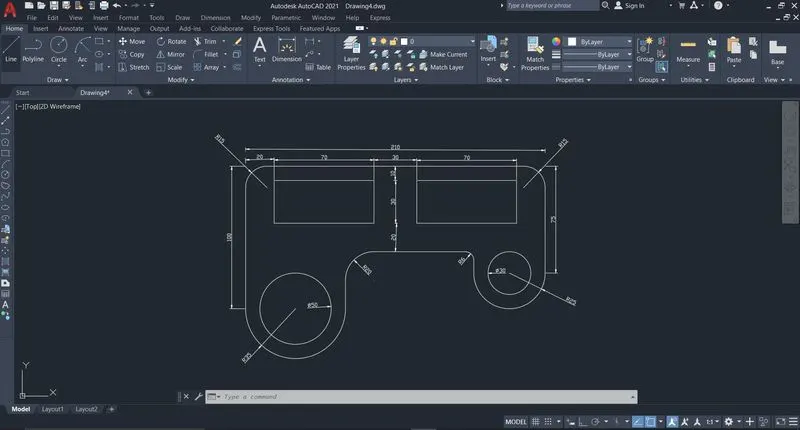
AIM: Creating the seventh drawing using AutoCAD.
INTRODUCTION:
AutoCAD is a commercial computer-aided design (CAD) and drafting software application. Developed and marketed by Autodesk, AutoCAD was first released in December 1982 as a desktop app running on microcomputers with internal graphics controllers. Before AutoCAD was introduced, most commercial CAD programs ran on mainframe computers or minicomputers, with each CAD operator (user) working at a separate graphics terminal. AutoCAD is also available as mobile and web apps.
AutoCAD is used in industry, by architects, project managers, engineers, graphic designers, city planners and other professionals.
PROCEDURE:
Step 1: Open AutoCAD by clicking on the AutoCAD icon on the Desktop
Step 2: Start a new project by clicking Ctrl + N on the keyboard. A "Create new drawing" dialogue box will appear.
Step 3: Choose Imperial Template and decimal units from advance option
Step 4: Commands used are as follows:
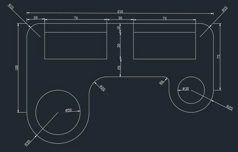
- Type 'PL' in the command prompt for polyline tool
- Click anywhere and at 90 degree specify the distance 100
- Again at 0 degree specify the distance 210
- Again at 270 degree specify the distance 75
- click esc to cancel the poly line command
- Type 'arc' in the command prompt for arc tool or from draw panel in the ribbon area choose arc tool and select the "start end radius" mode
- Now select the first point of the line as first point of the arc
- Specify the end point as @70,0 in the command prompt
- Select the radius option and specify the radius as 35 and the click enter
- Type 'arc' in the command prompt for arc tool or from draw panel in the ribbon area choose arc tool and select the "start end radius" mode
- Now select the first point of the line as first point of the arc
- Specify the end point as @-50,0 in the command prompt
- Select the radius option and specify the radius as 25 and the click enter by holding ctrl key
- Type 'XL' in the command prompt for construction line tool
- Choose the offset option and specify the offset as 20
- Select the left vertical line as the line object and click on the right direction
- Now select the last vertical line on the right as the line object and click on the left side
- Repeat the Construction line procedure by taking offset as 90
- Also repeat the construction line procedure for the horizontal line by taking offset as 10, 30 and 20
- Type 'TR' in the command prompt for Trim tool
- Select and trim all the unwanted lines using fence mode
- Type 'F' in the command prompt for Fillet tool
- Choose the radius mode and fillet all the corner points mentioned in the drawing by taking radius R15, R6 and R20
- Now make sure the object snap is turned on and 'center' is marked
- Type 'C' in the command prompt for Circle tool
- Choose the center of the first arc previously drawn and then select diameter mode and specify the diameter as 50
- Repeat the same procedure by selecting the center of the last arc previously drawn and specify diameter as 30
- For Dimensions type command dimlin, dimrad and dimdia in the command prompt.
Step 5: Type command "save". A "Save drawing as" dialogue box will appear. Choose the directory and file name and click the save button.
RESULT:
AIM: Creating the eighth drawing using AutoCAD.
INTRODUCTION:
AutoCAD is a commercial computer-aided design (CAD) and drafting software application. Developed and marketed by Autodesk, AutoCAD was first released in December 1982 as a desktop app running on microcomputers with internal graphics controllers. Before AutoCAD was introduced, most commercial CAD programs ran on mainframe computers or minicomputers, with each CAD operator (user) working at a separate graphics terminal. AutoCAD is also available as mobile and web apps.
AutoCAD is used in industry, by architects, project managers, engineers, graphic designers, city planners and other professionals.
PROCEDURE:
Step 1: Open AutoCAD by clicking on the AutoCAD icon on the Desktop
Step 2: Start a new project by clicking Ctrl + N on the keyboard. A "Create new drawing" dialogue box will appear.
Step 3: Choose Imperial Template and decimal units from advance option
Step 4: Commands used are as follows:
- Type 'XL' in the command prompt for construction line tool
- Select the horizontal mode and click anywhere in the screen
- Type 'XL' in the command prompt for construction line tool
- Select the vertical mode and click anywhere in the screen
- Type 'XL' in the command prompt for construction line tool
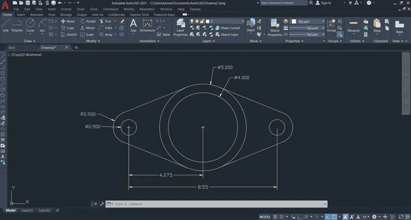
- Select the offset mode and specify the offset as 4.275
- Select the vertical line as the line object and click on the right direction
- Select the vertical line as the line object and click on the left direction
- Make sure the intersection is marked and object snap is turned on in the status bar
- Type 'C' in the command prompt for Circle tool
- Choose the intersection point of the mid construction lines as center of the circle and select diameter mode and then specify the diameter as 4
- Repeat the above procedure and specify diameter as 5
- Type 'C' in the command prompt for Circle tool
- Choose the intersection point of the right construction lines as center of the circle and select diameter mode and then specify the diameter as 0.90
- Repeat the above procedure, and this time specify the radius of the circle as 0.90
- Type 'CO' in the command prompt for Copy tool
- Select the center of the right circles as base point and then select then intersection of the left construction lines as second point
- Type 'E' in the command prompt for Erase tool
- Select all the construction lines and press enter to erase
- Make sure the tangent is marked in the object snap
- Type 'L' in the command prompt for Line tool
- Select the tangent of right outer circle as first point
- Select the tangent of mid outer circle as second point
- If the tangent doesnt meet then click on the end point of the line and drag to meet the tanget
- Repeat the above procedure for other three lines
- Type 'BR' in the commnad prompt for break tool
- Select first tangent point of the right outer circle as first point
- Select second tangent point of the right outer circle as second point
- Repeat the above procedure for the left side outer circle
- For Dimensions type command dimlin, dimrad and dimdia in the command prompt.
Step 5: Type command "save". A "Save drawing as" dialogue box will appear. Choose the directory and file name and click the save button.
RESULT:
AIM: Creating the nineth drawing using AutoCAD.
INTRODUCTION:
AutoCAD is a commercial computer-aided design (CAD) and drafting software application. Developed and marketed by Autodesk, AutoCAD was first released in December 1982 as a desktop app running on microcomputers with internal graphics controllers. Before AutoCAD was introduced, most commercial CAD programs ran on mainframe computers or minicomputers, with each CAD operator (user) working at a separate graphics terminal. AutoCAD is also available as mobile and web apps.
AutoCAD is used in industry, by architects, project managers, engineers, graphic designers, city planners and other professionals.
PROCEDURE:
Step 1: Open AutoCAD by clicking on the AutoCAD icon on the Desktop
Step 2: Start a new project by clicking Ctrl + N on the keyboard. A "Create new drawing" dialogue box will appear.
Step 3: Choose Imperial Template and engineering units from advance option
Step 4: Commands used are as follows:
- Type 'L' in the command prompt for Line tool
- Select first point anywhere
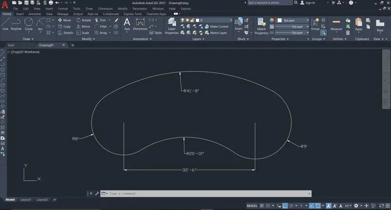
- Select second point at a distance 32'-6" in x-axis
- Press Esc to cancel the command
- Type 'C' in the command prompt for Circle tool
- Select the first end point of the line as the center of the circle and enter radius as 8'
- Type 'C' in the command prompt for Circle tool
- Select the last end point of the line as the center of the circle and enter radius as 9'
- Type 'C' in the command prompt for Circle tool
- Select the first end point of the line as the center of the circle and enter radius as 33'-8"
- Type 'C' in the command prompt for Circle tool
- Select the last end point of the line as the center of the circle and enter radius as 32'-8"
- Make sure the intersection in marked in object snap
- Type 'C' in the command prompt for Circle tool
- Select the intersection point of both circles drawn previously as the center of the circle and enter radius as 41'-8"
- Type 'TR' in the command prompt for Trim tool
- Select and trim all the unwanted lines and curves
- Type 'C' in the command prompt for Circle tool
- Select tan tan radius option in the command prompt
- Select the tangent of both circles drawn in the first phase and enter radius as 20'-10"
- Type 'TR' in the command prompt for Trim tool
- Select and trim all the unwanted lines and curves
- For Dimensions type command dimlin, dimrad in the command prompt.
Step 5: Type command "save". A "Save drawing as" dialogue box will appear. Choose the directory and file name and click the save button.
RESULT:
AIM: Creating the tenth drawing using AutoCAD.
INTRODUCTION:
AutoCAD is a commercial computer-aided design (CAD) and drafting software application. Developed and marketed by Autodesk, AutoCAD was first released in December 1982 as a desktop app running on microcomputers with internal graphics controllers. Before AutoCAD was introduced, most commercial CAD programs ran on mainframe computers or minicomputers, with each CAD operator (user) working at a separate graphics terminal. AutoCAD is also available as mobile and web apps.
AutoCAD is used in industry, by architects, project managers, engineers, graphic designers, city planners and other professionals.
PROCEDURE:
Step 1: Open AutoCAD by clicking on the AutoCAD icon on the Desktop
Step 2: Start a new project by clicking Ctrl + N on the keyboard. A "Create new drawing" dialogue box will appear.
Step 3: Choose Imperial Template and decimal units from advance option
Step 4: Commands used are as follows:
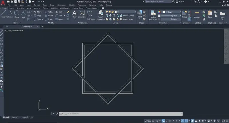
- Type 'pol' in the command prompt for polygon tool
- Select the side as 4
- Select the center anywhere in the screen
- Select any inscribed or circumscribed option
- Mention the radius of the circle and press enter
- Type 'O' in the command prompt for offset tool
- Enter the offset value and select the side to offset
- Type 'CO' in the command prompt for Copy tool
- Select both rectangles drawn previously and press enter
- Click on the geometric center as the base point
- Click on the geometric center as the end point
- Type 'RO' in the command prompt for Rotate tool
- Select the geometric center as the base point
- Enter 45 degree as the angle of inclination
Step 5: Type command "save". A "Save drawing as" dialogue box will appear. Choose the directory and file name and click the save button.
RESULT:
AIM: Creating the eleventh drawing using AutoCAD.
INTRODUCTION:
AutoCAD is a commercial computer-aided design (CAD) and drafting software application. Developed and marketed by Autodesk, AutoCAD was first released in December 1982 as a desktop app running on microcomputers with internal graphics controllers. Before AutoCAD was introduced, most commercial CAD programs ran on mainframe computers or minicomputers, with each CAD operator (user) working at a separate graphics terminal. AutoCAD is also available as mobile and web apps.
AutoCAD is used in industry, by architects, project managers, engineers, graphic designers, city planners and other professionals.
PROCEDURE:
Step 1: Open AutoCAD by clicking on the AutoCAD icon on the Desktop
Step 2: Start a new project by clicking Ctrl + N on the keyboard. A "Create new drawing" dialogue box will appear.
Step 3: Choose Imperial Template and engineering units from advance option
Step 4: Commands used are as follows:
- Turn on the ortho by pressing F8 key
- Type 'PL' in the command prompt for Polyline tool
- Specify first point by clicking anywhere in the screen
- Specify next point at 0 degree 3'
- Specify next point at 270 degree 9'
- Specify next point at 180 degree 3'
- Specify next point at 270 degree 4'-6"
- Specify next point at 180 degree 4'-6"
- Specify next point at 90 degree 1'-2"
- Specify next point at 180 degree 5'-4"
- Specify next point at 270 degree 1'-2"
- Specify next point at 180 degree 4'-6"
- Specify next point at 90 degree 4'-6"
- Specify next point at 180 degree 3'
- Specify next point at 90 degree 9'
- Specify next point at 0 degree 3'
- Press esc to cancel the polyline command
- Type 'XL' in the command prompt for construction lines
- select vertical option and click on the mid point of the drawing
- Type 'XL' in the command prompt for construction lines
- select offset option and specify the offset as 2'-8"
- Select the top line as object line and click on the bottom side of the line
- Type 'XL' in the command prompt for construction lines
- select offset option and specify the offset as 3'-7"
- Select the top line as object line and click on the bottom side of the line
- Type 'XL' in the command prompt for construction lines
- select offset option and specify the offset as 6'-9"
- Select the top line as object line and click on the bottom side of the line
- Type 'PL' in the command prompt for Polyline tool
- Make sure the polar tracking is turned on and set to 45 degree
- Also make sure the intersection is marked in the object snap
- Specify first point by clicking on the last point of the drawing
- Specify next point by taking an angle of 315 degree through polar tracking click on the nearest point on construction line
- Specify next point by taking an angle of 45 degree through polar tracking click on the intersection point of the last point of the horizontal line drawn
- Specify next point by taking an angle of 0 degree through polar tracking click on the nearest point on construction line
- Press Esc to cancel the polyline command
- Type 'PL' in the command prompt for Polyline tool
- Make sure the polar tracking is turned on and set to 30 degree
- Specify first point by clicking on the first point of the drawing
- Specify next point by taking an angle of 240 degree through polar tracking click on the nearest point on construction line
- Specify next point by taking an angle of 120 degree through polar tracking click on the intersection point of the first point of the horizontal line drawn
- Specify next point by taking an angle of 180 degree through polar tracking click on the nearest point on construction line
- Press Esc to cancel the polyline command
- Type 'Rec' in the command prompt for rectangle tool
- Specify the first point anywhere in the screen
- Specify the second point as @3',3'
- Type 'M' in the command prompt for Move tool
- Select the rectangle and press enter
- Select the base point as the geometric center of the rectangle
- Click on the intersection point of the Construction lines drawn at an offset of 6'-9" and the Mid vertical as the second point
- Type 'RO' in the command prompt for Rotate tool
- Specify the base point as the geometric center of the rectange
- Specify the angle as 45 degree
- Type 'E' in the command prompt for Erase tool
- Select and erase all the construction lines
- For Dimensions type command dimlin, dimang in the command prompt.
Step 5: Type command "save". A "Save drawing as" dialogue box will appear. Choose the directory and file name and click the save button.
RESULT: