Creating a Layout, Section and Elevation with dimensions using AutoCad
AIM: Creating a G+3 Plan, Section and Elevation using AutoCAD.
INTRODUCTION:
- AutoCAD is a commercial computer-aided design (CAD) and drafting software application. Developed and marketed by Autodesk, AutoCAD was first released in December 1982 as a desktop app running on microcomputers with internal graphics controllers. Before AutoCAD was introduced, most commercial CAD programs ran on mainframe computers or minicomputers, with each CAD operator (user) working at a separate graphics terminal. AutoCAD is also available as mobile and web apps.
- AutoCAD is used in industry, by architects, project managers, engineers, graphic designers, city planners and other professionals.
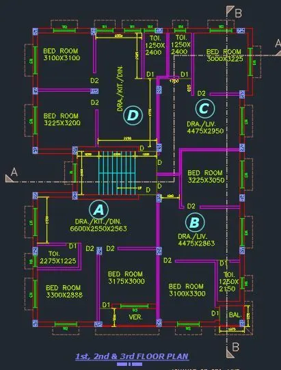
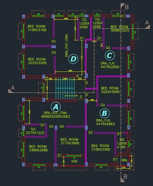
- In the following project the building consists of one ground and 3 floors. Each floor have 4 flats naming A,B,C and D. The plan for each floor excluding ground is similar.
- The Dimensions assumed for exterior wall is 250 and interior wall is 125.
- The dimensions of the doors and windows are assumed as follows
- Main door D = 1000x2100
- D1= 750 X 2000
- D2= 900 X 2000
- W=1000x1500
- W1= 900X1200
- W2=1200X1200
- W3=1500X1200
- W4=600X600
- The column dimension is assumed as 250X350 and 250X400
- The basic autocad tools that can be used to draw the plan, section and elevation are draw tools and modify tools.
PROCEDURE:
Step 1: Open AutoCAD by clicking on the AutoCAD icon on the Desktop
Step 2: Start a new project by clicking Ctrl + N on the keyboard. A "Create new drawing" dialogue box will appear.
Step 3: Choose Advance option and select decimal and precision to 0
Step 4: Commands used are as follows
- Type 'UN' in the command prompt and set the units to decimal and set the precision as per the data given and insertion scale as millimeter
- Type 'Limit' and specify lower unit as 0,0 and upper unit as 50000,50000
- Type 'Zoom' and select All
Part A: Creating the Plan
- Type 'XL' for construction lines and draw two construction lines horizontal and vertical
- Type 'O' for offset tool and offset both lines at a distance of 250
- Now Type 'O' and offset the offsetted vertical line by specifying the offset distance as 3300
- Similarly using offset tool, offset the vertical lines at distances 125, 3175, 125, 125, 3100, 125, 1250, 250
- Type 'F' for fillet tool and choose radius as 0 and fillet the bottom exterior lines
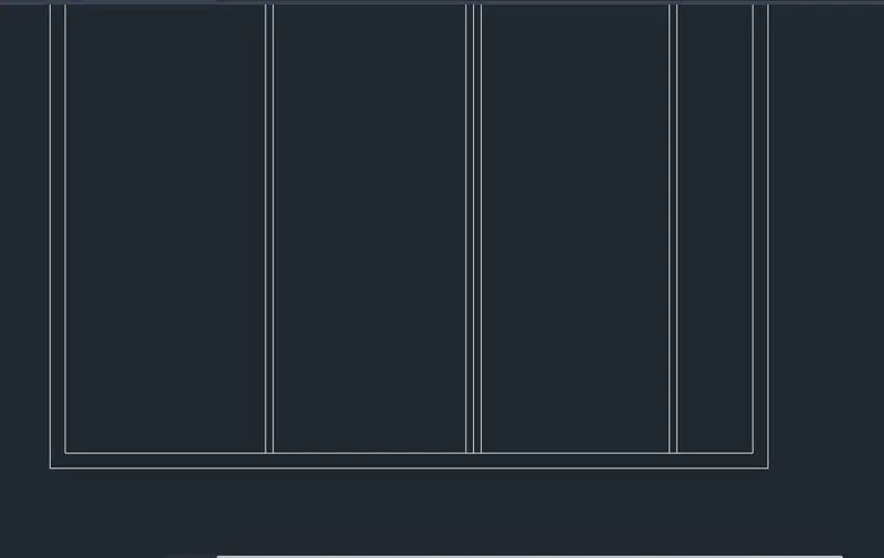
- Now Type 'O' and offset the offsetted horizontal line by specifying the offset distance as 2888
- Similarly using offset tool, offset the horizontal lines with distances mentioned in the diagram
- Using offset tool and line tool draw other rooms in the diagram including the staris.
- Using Trim tool trim off the unwanted lines
- Make two rectangles using rectangle tool with dimension 250x350 and 250x400
- Copy the above rectangle to the walls wherever columns are placed
- Use rotate tool to modify the rectangles and using move tool move it in the required places
- For door openings use offset tool at a distance 1000 for D, 900 for D2 and 700 for D1
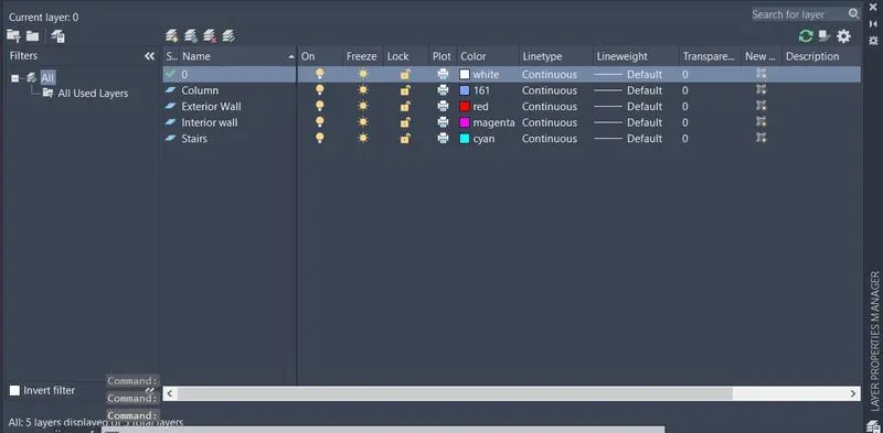
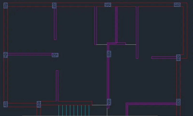
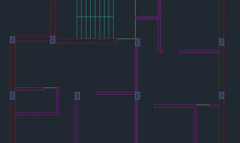
- Once the sketching is done, go to layer properties and create some new layers given as exterior walls, interior walls, stairs, and columns
- Give distinct colors to different layers and assign the objects to respective layers
- Now type 'Hatch' and select AR-Conc and click in the column area and scale it to 15
- Select the hatch area and assign it to column layer
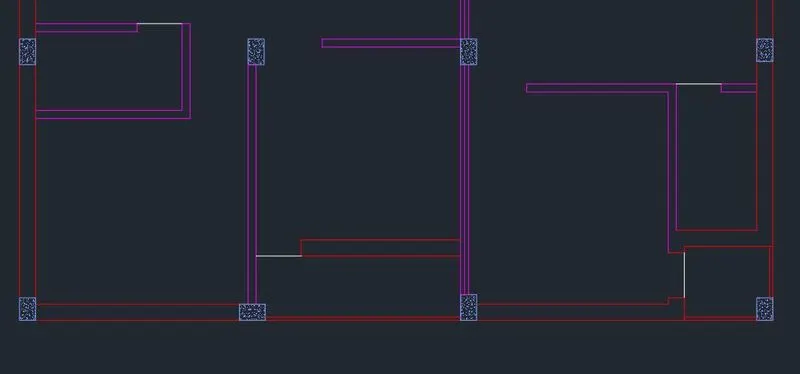
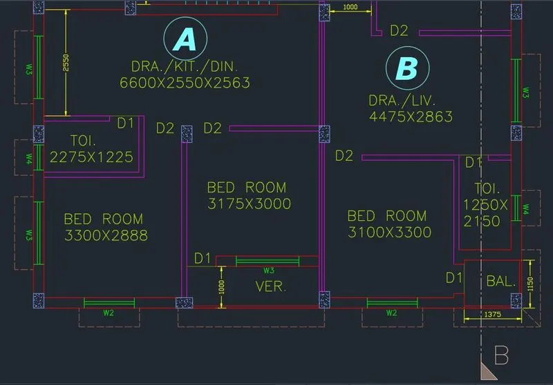
- Following is the result of the above procedure
- Type 'L' for line tool and click anywhere
- press F8 to turn on the ortho
- Now direct the cursor vertically and enter distance 250
- Press Esc to cancel the command
- Now Type 'O' for offset and specify the offset distance as 900 which is the plan length of W1
- Offset it in the right side
- Now with line tool draw a line connecting both mid point of the vertical line
- Now with offset tool, offset the line previously drawn at a distance 30 both in top and bottom
- Select the mid line and erase it with erase tool
- Similarly Draw the other windows using the above procedure
- Now go to layer properties and create a new layer naming Windows and assign the objects to that layer
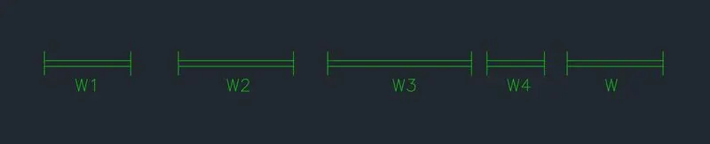
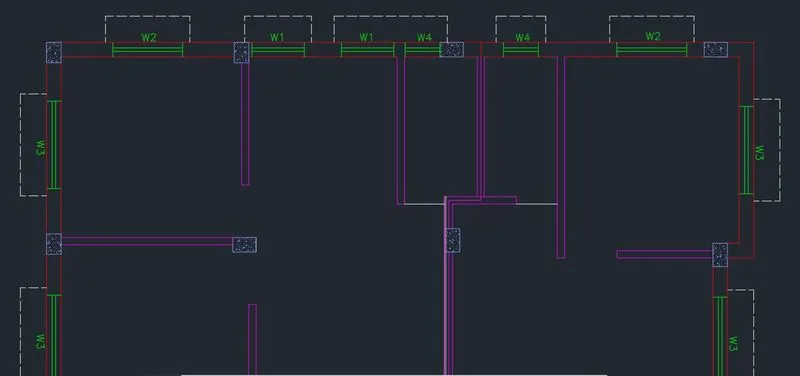
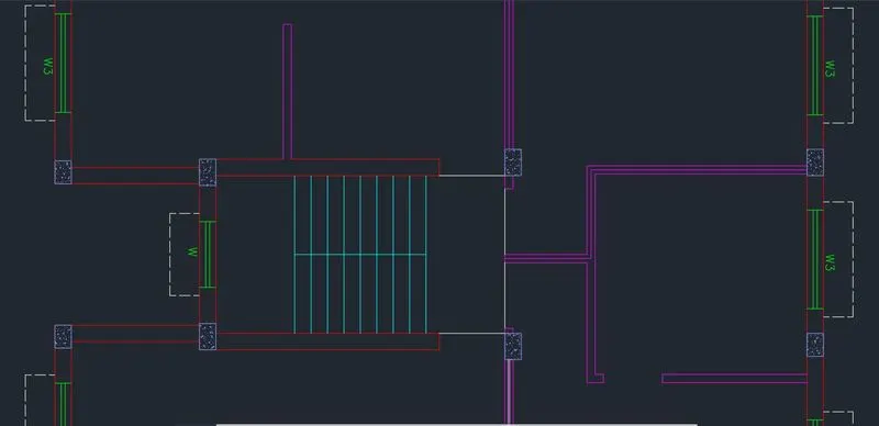
- Now Copy these objects using copy tool and paste it in the respective positions
- Draw Chajja at an offset of 450 outward from the windows
- Change the line type of the chajja to ACAD_ISO02W100 and scale it to 15
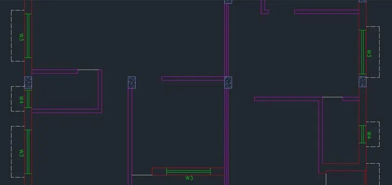
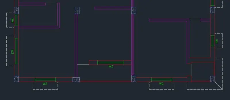
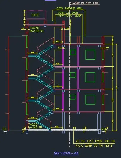
PART B: Creating the section-AA:
- Create a new layer naming Construction line and set it to current
- Type 'XL' to invoke contruction line tool and select vertical option
- Now Select the walls intersections
- Type 'XL' and draw a horizontal construction lines
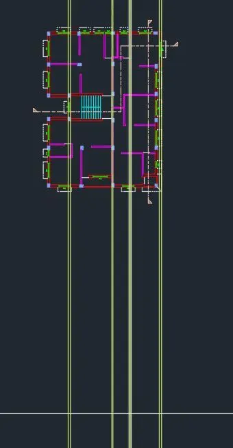
- Change the current layer to 0 layer or default layer. Later we can assign the objects to different layer.
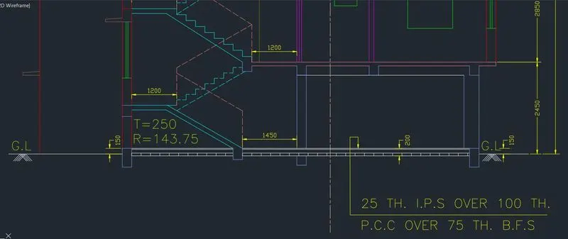
- With the help of offset tool draw the base level of the section by taking offset distances as 75mm for BFS, 100 mm for PCC and 25mm of IPS flooring
- In the similar way offset the IPS line downward at a distance 150. This is the G.L
- Use trim tool to trim off the unwanted lines
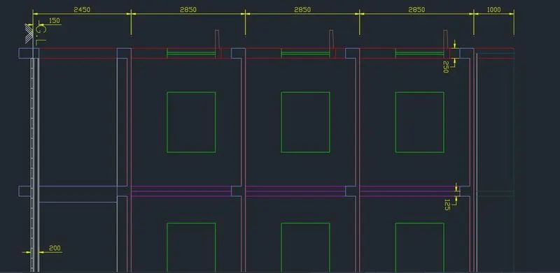
- Using offset tool, offset the floor height and slab width at 2450
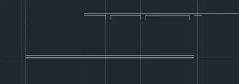
- Now using copy tool and multiple option, copy the slab and beam drawn and paste it at height 2850 (before doing this offset a refrence line at 2850 to make the object be pasted at that level)
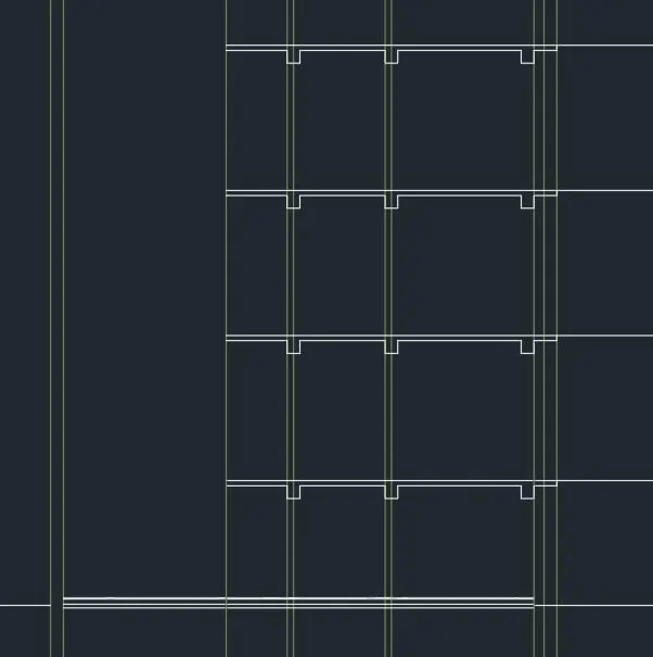
- Using line tool draw the walls and other beams which were not sketched previously
- Use trim tool to trim off the unwanted lines
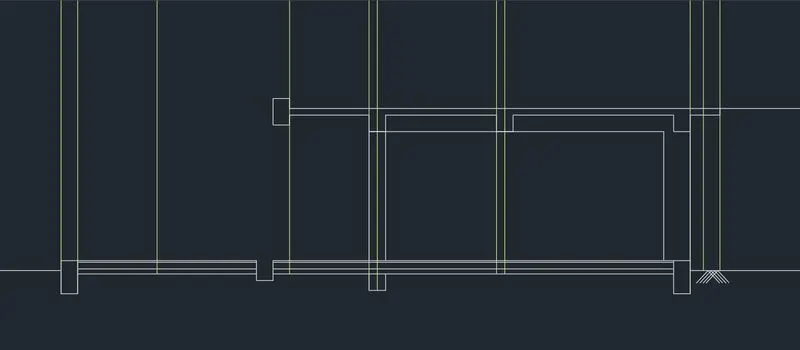
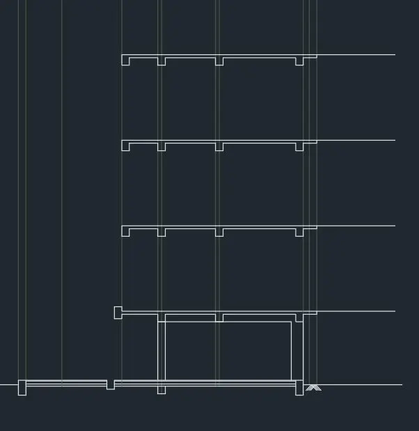
- Type 'L' for line tool and draw the right exterior wall of the first floor
- use offset tool to draw the sill level and window height by taking offset of sill level as 900 and window height as 1200
- Similarly draw the chajja using offset tool and line tool
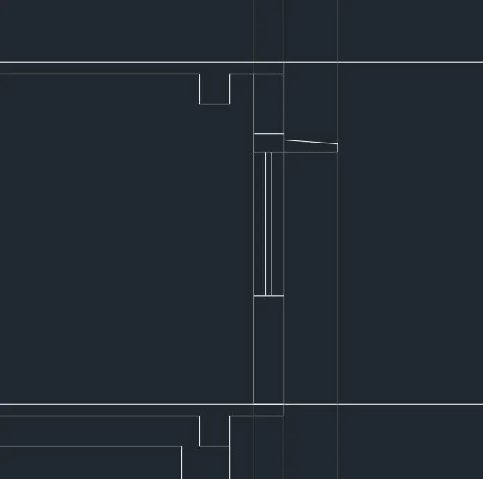
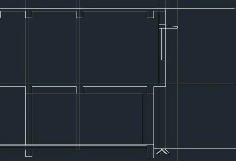
- Now copy the exterior wall including chajja and choose multiple option and paste it in every floor in the right side of the building
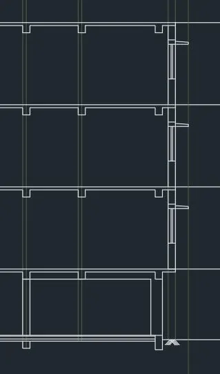
- Similarly follow the same procedure for the other walls too in the first floor
- By typing 'XL' in the command prompt, draw vertical construction lines taking point on W2 and W4
- Take offset of sill level as 900 for windows and using line tool complete the windows
- The other small window can be drawn taking offset as 600 from top horizontal line
- Now Copy every object using copy tool and paste it in the other floors
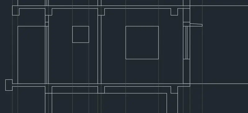
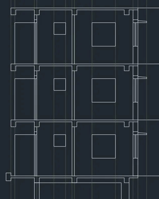
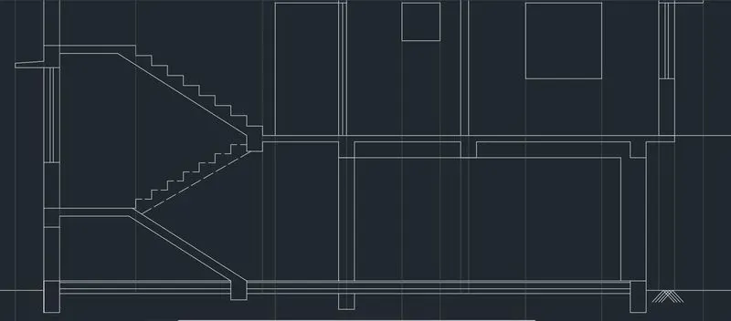
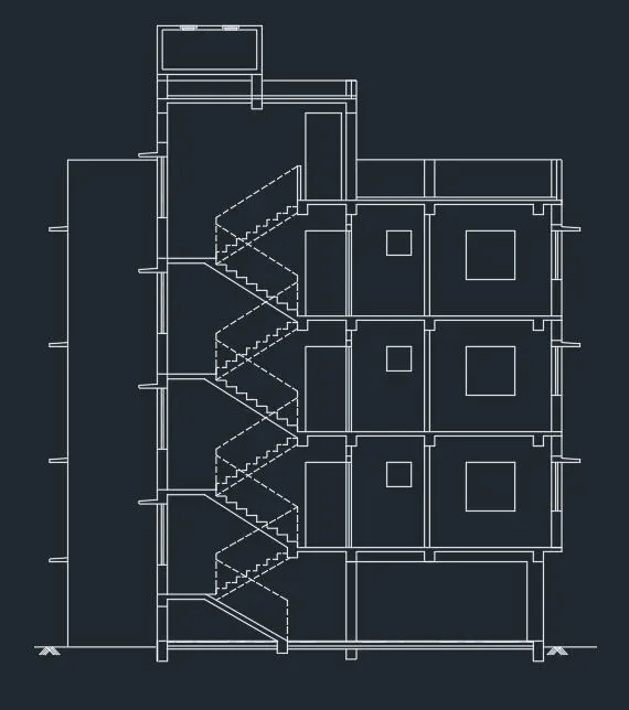
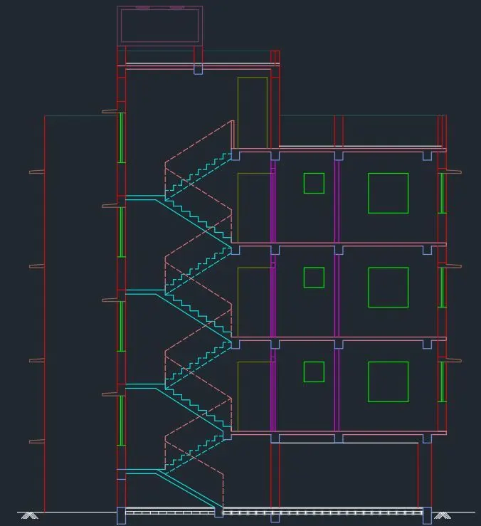
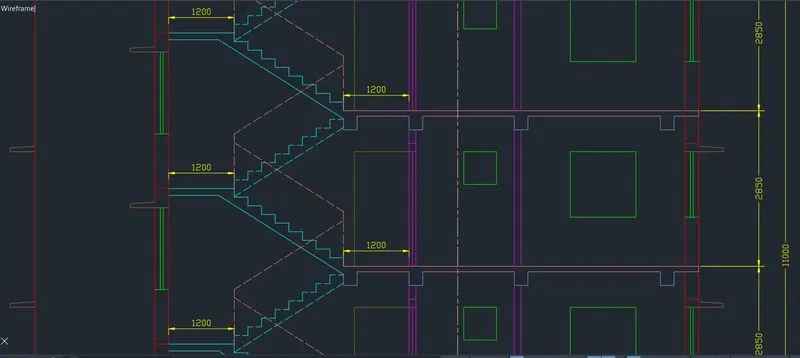
- For sketching the stair of the ground floor, first draw the midlanding using line tool (the midlanding is placed at the center of the floor height)
- Now draw the steps (which measures tread as 250 and rise as 143.75) with the help of line tool
- Now copy the first tread and rise using copy tool and paste it accordingly
- Similarly draw the midlanding and stairs of the other floors.
- The Tread is 250 and rise is 158.33 of the other floors
- Draw the window and chajja using similar procedure mentioned previously while sketching the window and chajja portion
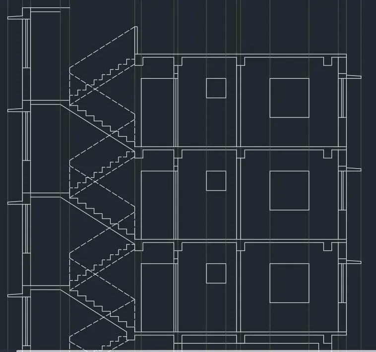
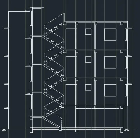
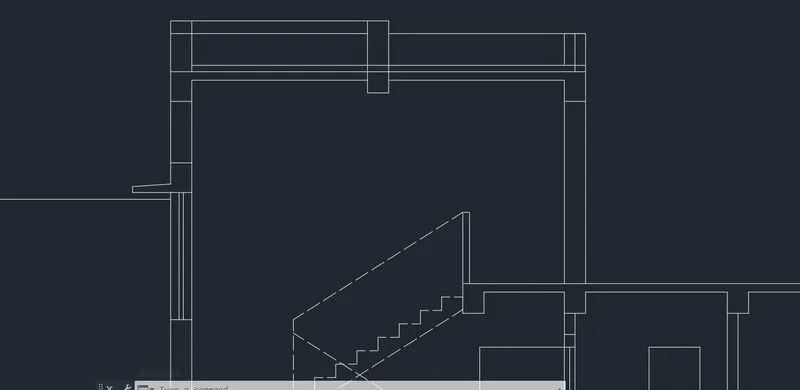
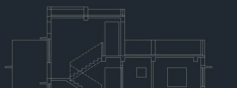
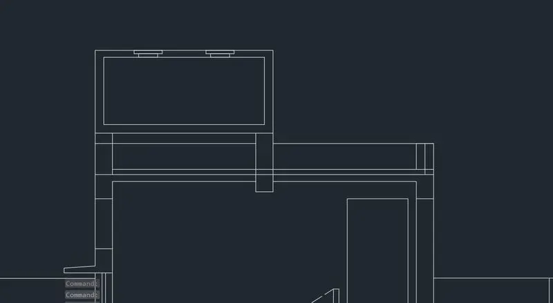
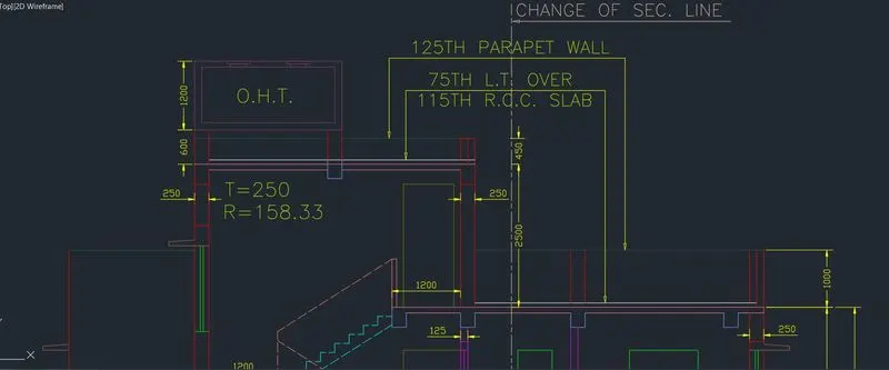
- Now using line tool and offset tool draw the top of the building including over head tank
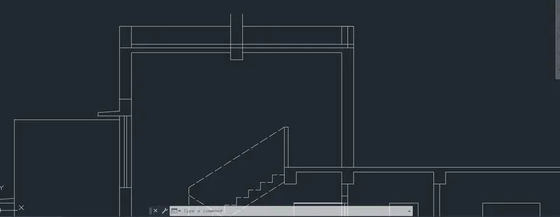
- Create more new layers as follows
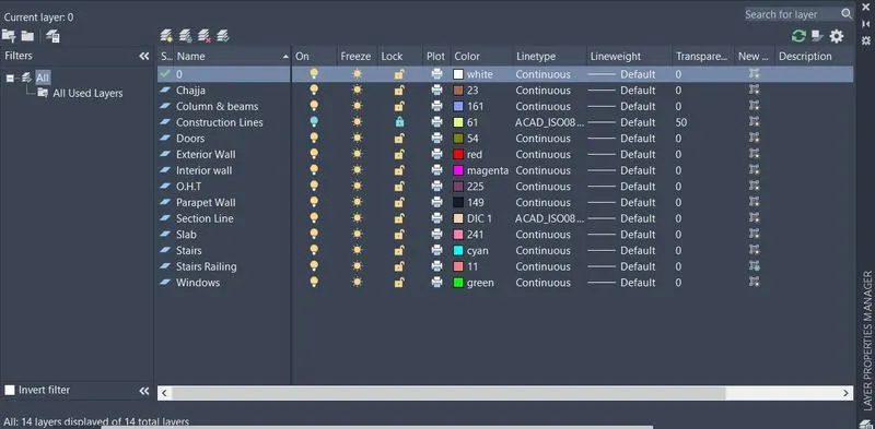
- Now assign all the objects to the corresponding layers
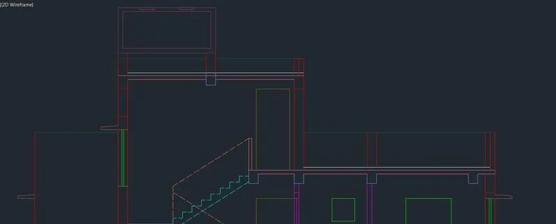
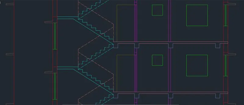
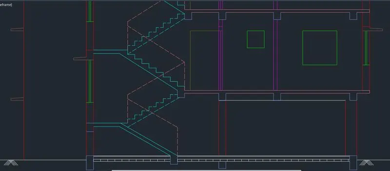
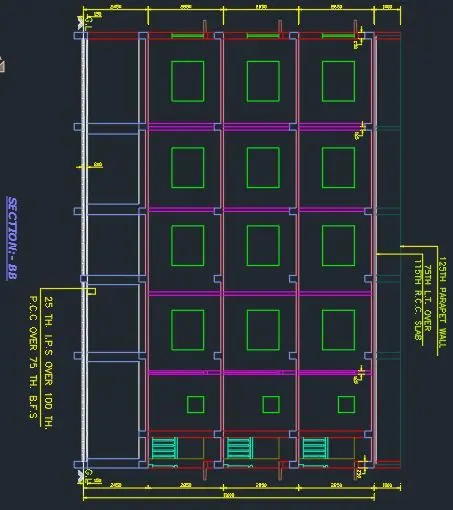
PART C: Creating the Section-BB:
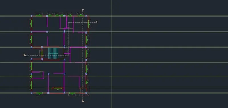
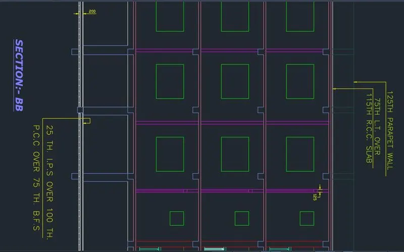
- Type 'XL' to invoke construction line tool and select horizontal and click on the points on the walls (after constructing the wall we can later draw more contruction lines to draw other aspects of the drawing)
- Again Type ''XL' and select vertical line and then click just right side of the Plan
- The tools used to draw the elevation is similar to those of section as the dimensions are same, copying the floor objects to other floors will make it easier to draw
- Draw the bottom floor taking offset as 75, 100 and 25
- Similarly using offset tool draw a line taking offset distance as 2450 from G.F
- And in similar way we can draw the other floors while assigning the objects to the respective layers
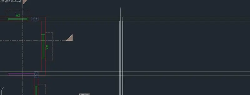
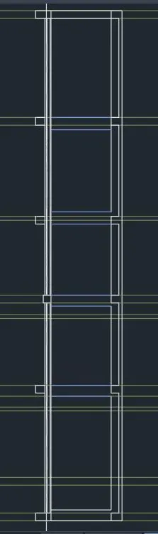
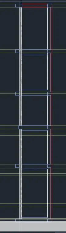
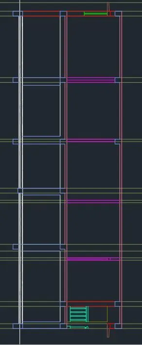
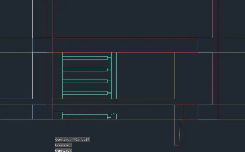
- Now Type 'XL' and select horizontal lines and then click on the window points
- Using Construction lines draw the windows
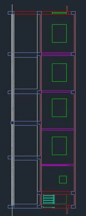
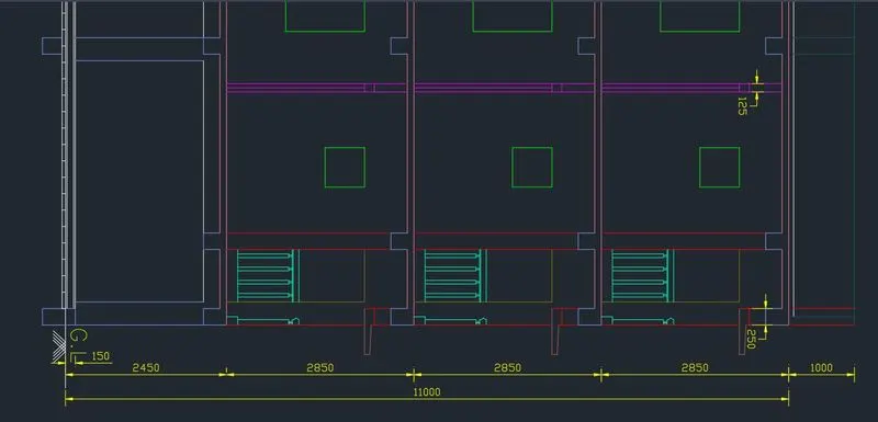
- Now select all the objects in the first floor including the slab and select multiple option and past it accordingly in the second and third floor area (Choose the any bottom left base point near the ground floor slab)
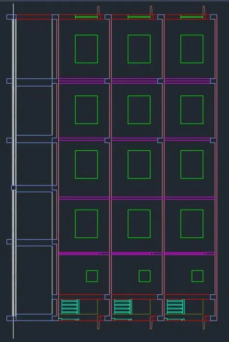
- Type 'O' for offset tool and specify the offset as 1000 and select the top slab and offset the line to draw parapet wall
- Using Line tool and offset tool draw other aspects of the digram
- See if theres any correction needed
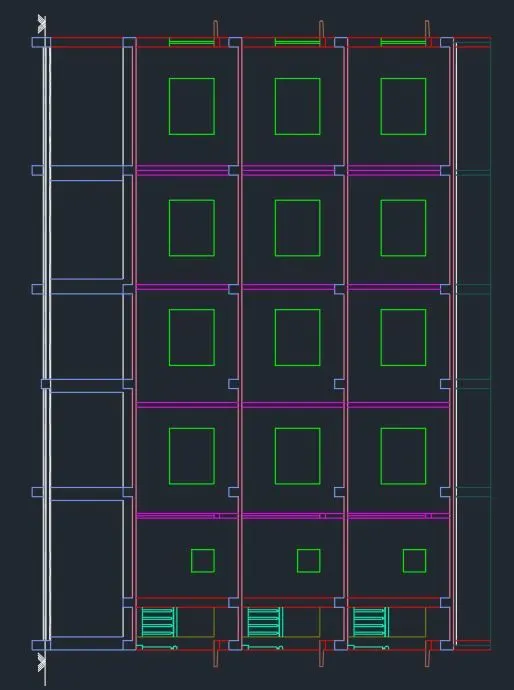
PART D: Annotaion:
- Create two new layers naming Texts, Dimensions and Texts(Flat Name)
- Type 'Mtext' and insert texts wherever necessary
- Using Dimlin command insert dimensions wherever necessary
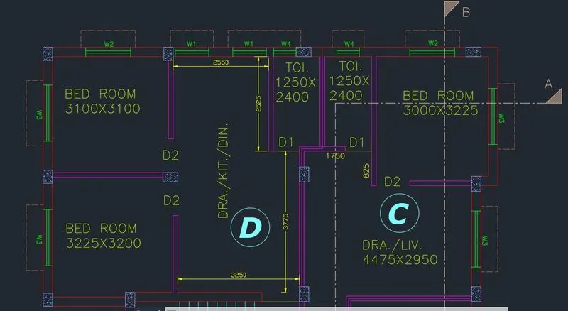
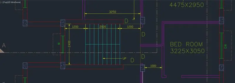
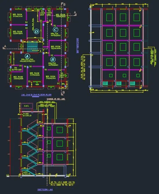
RESULT:
- Following is the resultant figure of the PLAN, SECTION-AA and SECTION-BB: