Creating Kitchen layout, Hatching of Architectural elements and sectional view of an Industrial Building in AutoCad
AIM: Creating a Kitchen Layout using AutoCAD.
INTRODUCTION:
AutoCAD is a commercial computer-aided design (CAD) and drafting software application. Developed and marketed by Autodesk, AutoCAD was first released in December 1982 as a desktop app running on microcomputers with internal graphics controllers. Before AutoCAD was introduced, most commercial CAD programs ran on mainframe computers or minicomputers, with each CAD operator (user) working at a separate graphics terminal. AutoCAD is also available as mobile and web apps.
AutoCAD is used in industry, by architects, project managers, engineers, graphic designers, city planners and other professionals.
The kitchen layout can be sketched using draw tools like Line tool, Offset tool, rectangle tool, arc tool etc., and it can be modified by trim tool, copy tool, rotate tool, erase tool etc.
PROCEDURE:
Step 1: Open AutoCAD by clicking on the AutoCAD icon on the Desktop
Step 2: Start a new project by clicking Ctrl + N on the keyboard. A "Create new drawing" dialogue box will appear.
Step 3: Choose 'metric' and click OK.
Step 4: Commands used are as follows:
- Type 'UN' in the command prompt and set the units to decimal and set the precision as per the data given and insertion scale as millimeter
- Type 'Limit' and specify lower unit as 0,0 and upper unit as 10000,10000
- Type 'Zoom' and select All
- Type 'XL' for construction line tools and draw two construction lines vertical and horizontal
- Type 'O' for offset tool and offset both lines at a distance of 230
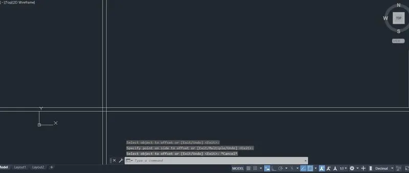
- Type 'O' for offset tool and offset the top horizontal line at a distance of 3200
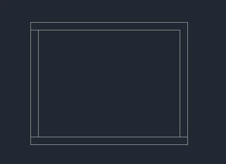
- Type 'O' for offset tool and offset the previous offsetted horizontal line at a distance of 230
- Type 'O' for offset tool and offset the right vertical line at a distance of 4230
- Type 'O' for offset tool and offset the previous offsetted vertical line at a distance of 230
- Using Trim tool, trim off the unwanted lines
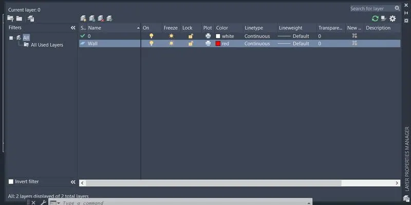
- Create a new layer from layer properties and name it "wall"
- Assign all the above drawn lines to layer wall
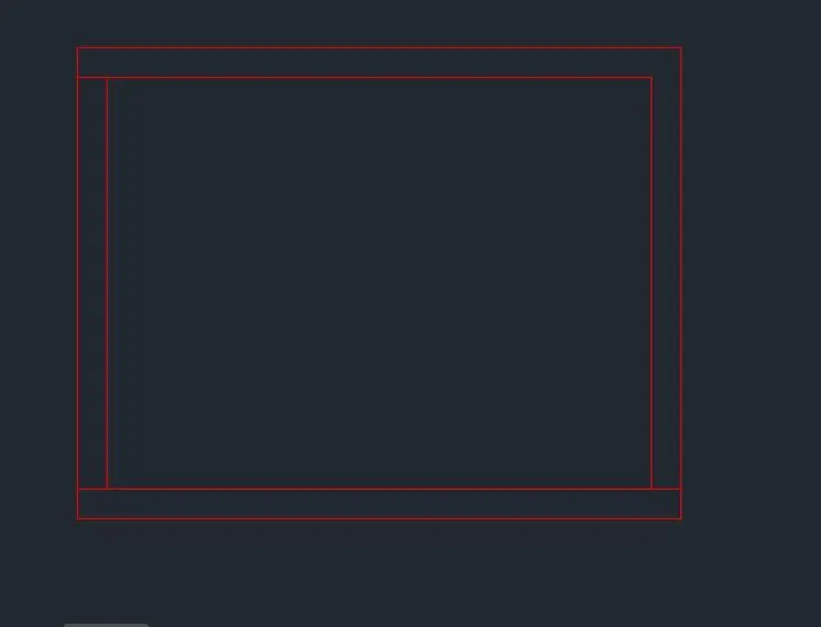
- Using Line tool and Offset tool draw the Door opening taking distance of the door opening as 1050 and other door opening as 850
- Draw the other components using arc tool
- Using Line tool and offset tool draw the window openings and other components also.
- Create a New Layers naming Door and Window from layer properties and assign the door objects to Door layer and window object to window layer
- Similarly do the same procedure for window openings
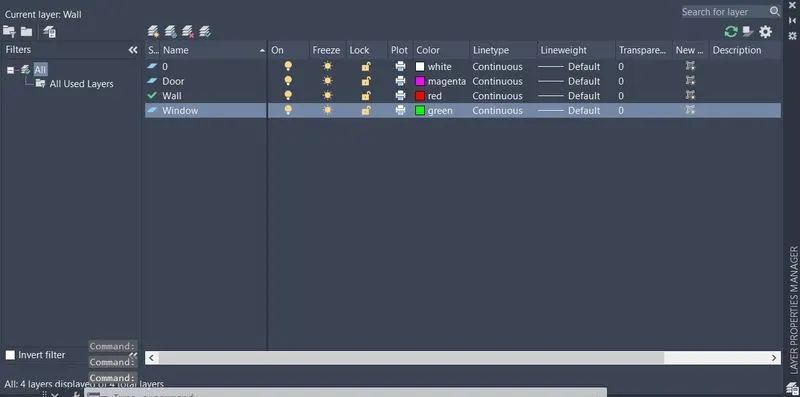
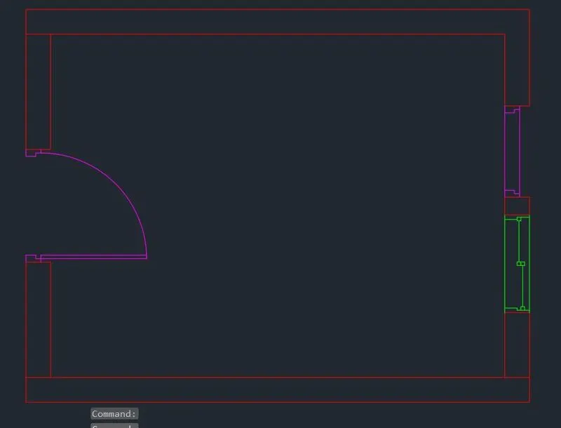
- Type 'Hatch' and seletc Ansi132 and click on the wall area.
- Type 'Hatchedit' and select the hatched area and set the scale to 200
- Type 'Hatch' and select Solid and click on the wall area
- Type 'Hatchedit' and select the hatched area and set the transparency to 60
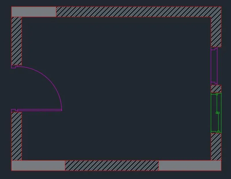
- Now copy whole object using copy tool and paste it right side of it. (this is done because the dimensions are same for the other plan)
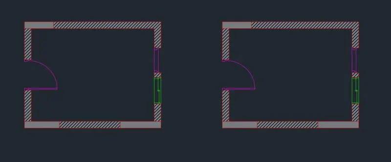
- Now using line tool and offset tool draw the kitchen equipments for the below counter plan.
- Trim off the unwanted lines using trim tool
- Distances are mentioned, therefore offset the lines in the following distances.
- Change the linetype wherever necessary from Linetype in the ribbon panel. Scale it to make it visible.
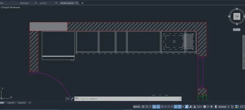
- Similarly using line tool and offset tool draw the other equipments of the below counter plan
- Use Circel tool and Line tool for the HOB area
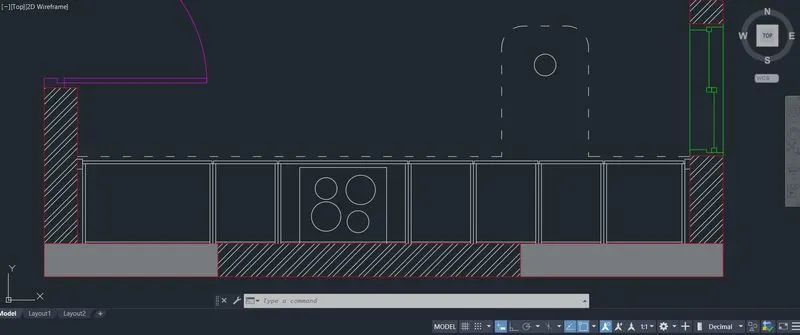
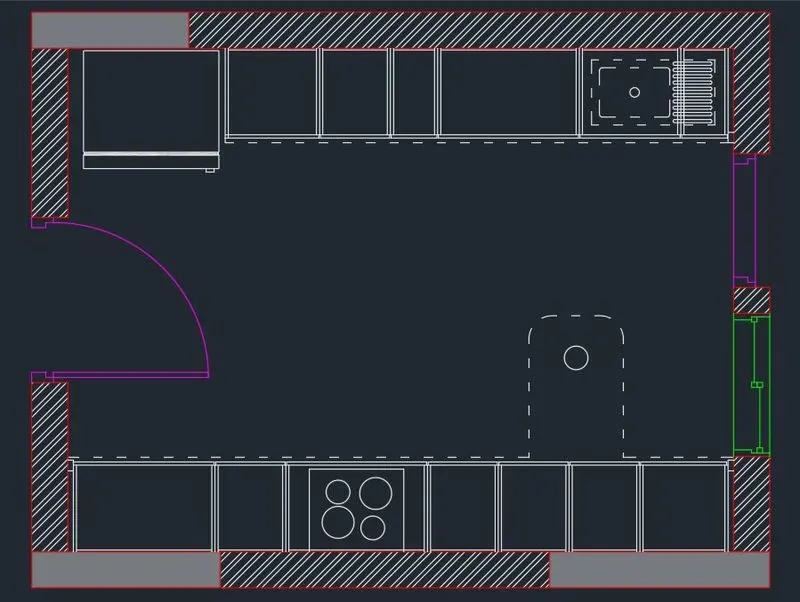
- Similarly using line tool and offset tool draw the other aspects of the 'Above counter plan'
- Use trim tool to trim off the unwanted lines
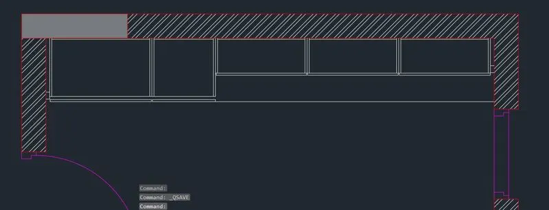
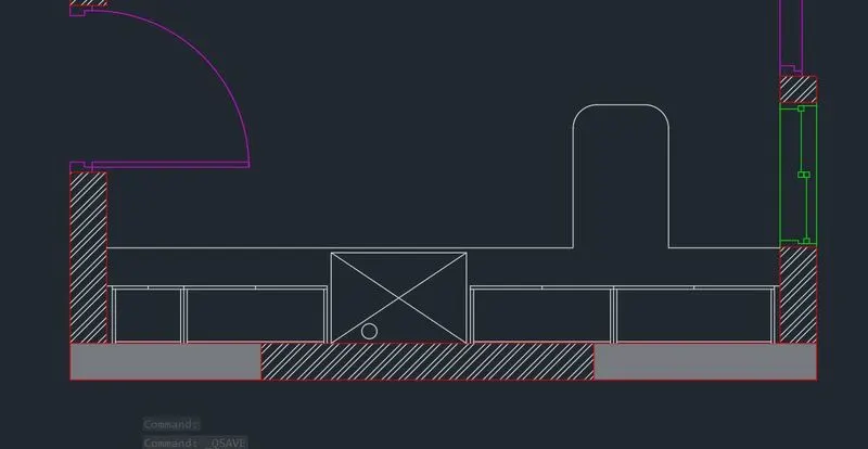
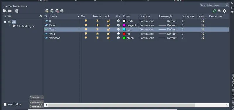
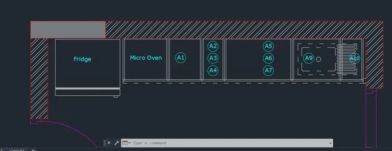
- Create a new layer and name it Texts. Choose this layer as current layer and with the mtext tool specify all the texts in the diagram
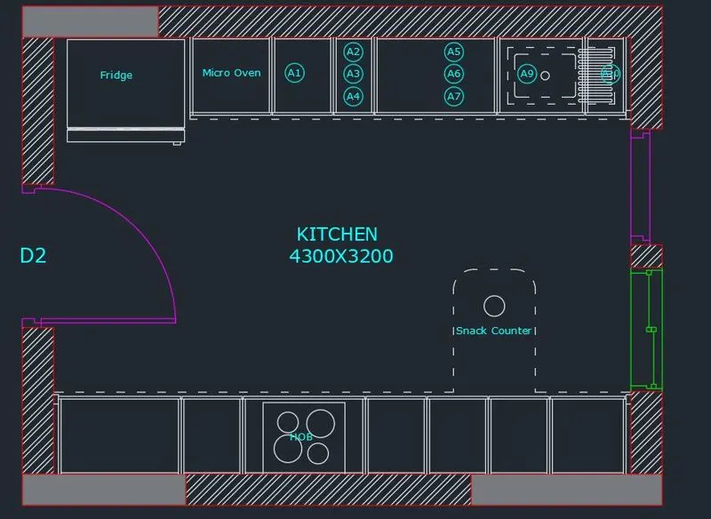
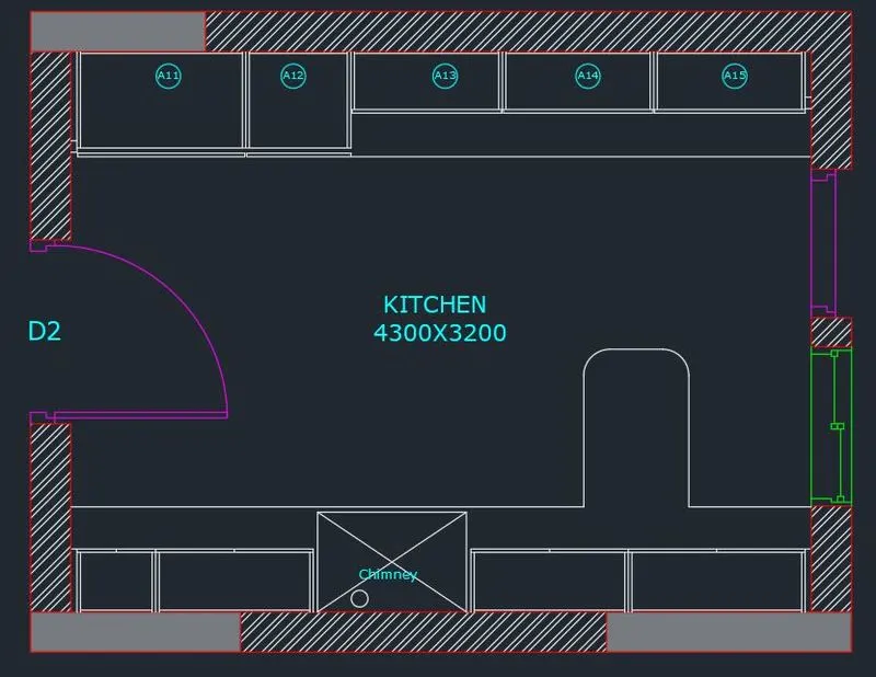
- Create a new layer and name it Dimesnions and set it to current.
- Now using Dimlin command give proper dimension to the drawing
- Use Dimcontinue command for easy and quick dimensioning
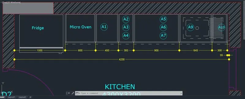
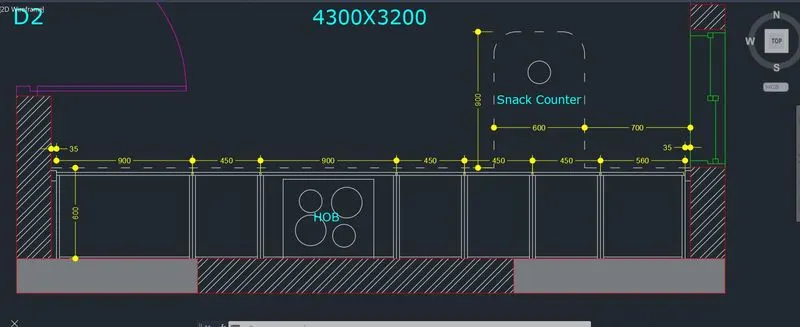
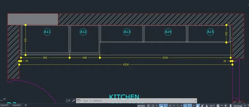
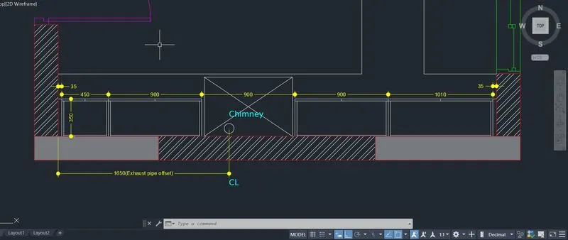
RESULT:
- Create a new layer naming Heading text and set it to current and with the mtext command write the drawing heading beneath the drawing.
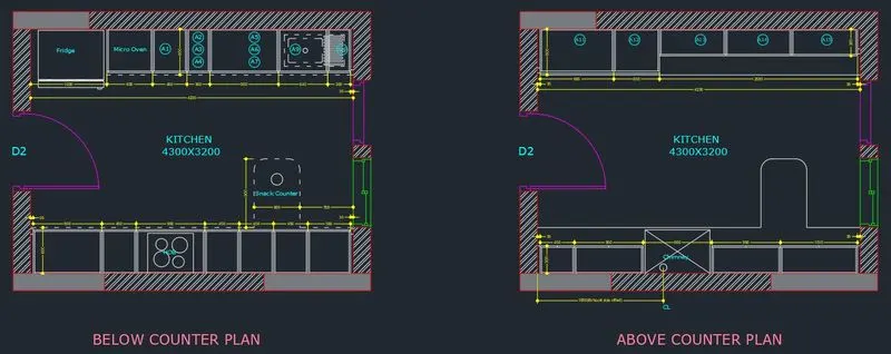
- Following is the complete sketch.
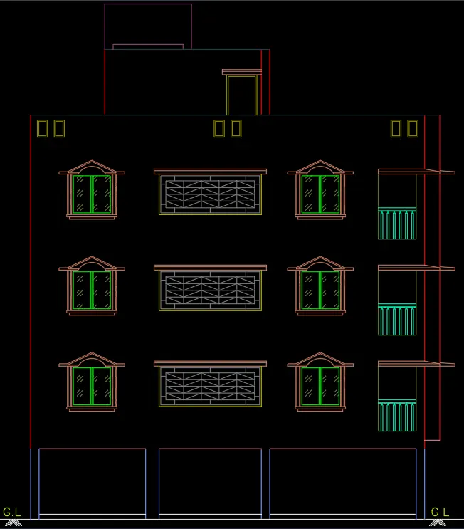
AIM: Create the elevation of the plan created in the Challenges 7 and apply proper hatch in the walls, doors, windows, and other architectural elements using AutoCAD.
INTRODUCTION:
AutoCAD is a commercial computer-aided design (CAD) and drafting software application. Developed and marketed by Autodesk, AutoCAD was first released in December 1982 as a desktop app running on microcomputers with internal graphics controllers. Before AutoCAD was introduced, most commercial CAD programs ran on mainframe computers or minicomputers, with each CAD operator (user) working at a separate graphics terminal. AutoCAD is also available as mobile and web apps.
AutoCAD is used in industry, by architects, project managers, engineers, graphic designers, city planners and other professionals.
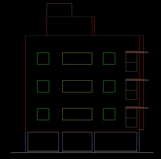
The Elevation can be made from projected lines from the plan using construction line tool.
PROCEDURE:
Step 1: Open AutoCAD by clicking on the AutoCAD icon on the Desktop
Step 2: Start a new project by clicking Ctrl + N on the keyboard. A "Create new drawing" dialogue box will appear.
Step 3: Choose 'metric' and click OK.
Step 4: Commands used are as follows:
- Type 'UN' in the command prompt and set the units to decimal and set the precision as per the data given and insertion scale as millimeter
- Type 'Limit' and specify lower unit as 0,0 and upper unit as 10000,10000
- Type 'Zoom' and select All
- Open the Challenge 7 .dwg file.
- Go to layer properties and select construction lines as current layer.
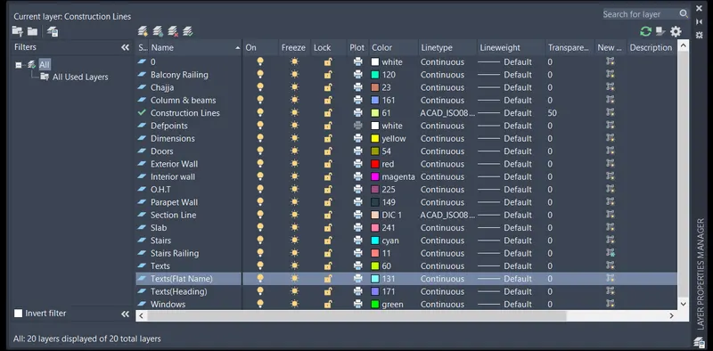
- Type 'XL' and choose vertical.
- Select the column points and exterior walls.
- Type 'XL' and choose horizontal.
- Select the G.L point, I.P.S flooring Point, the bottom of beam of G.L, the parapet walls and top of O.H.T.
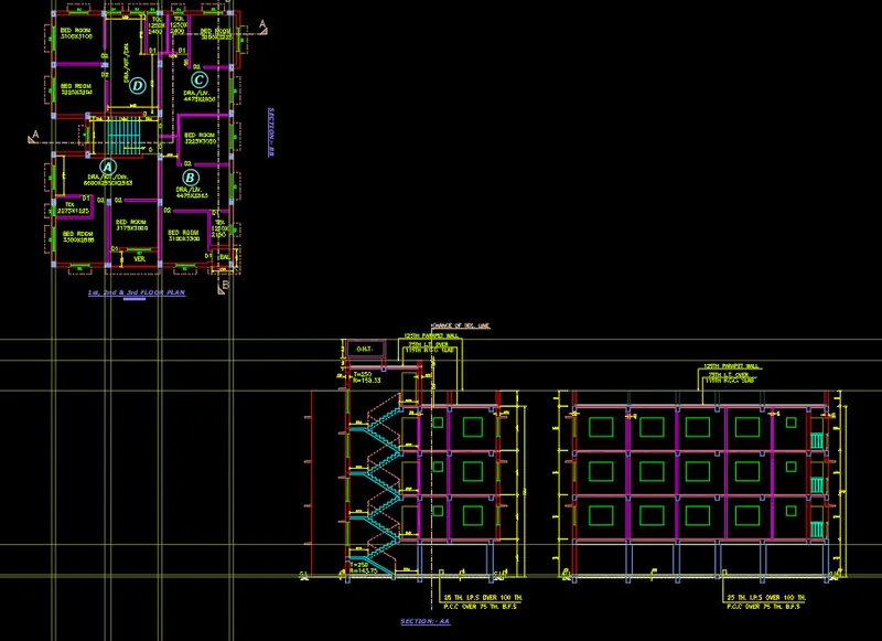
- Using trim tool trim off the unwanted lines.
- Also draw the O.H.T using line tool.
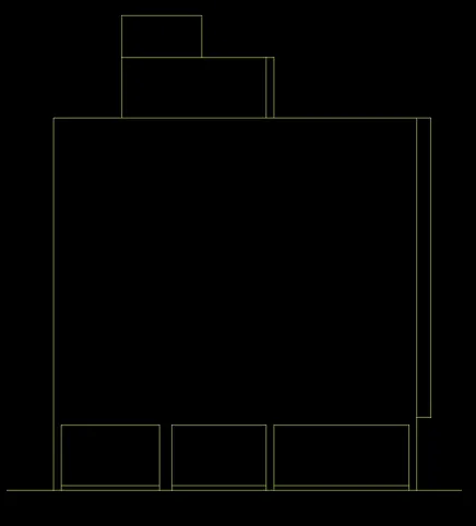
- Type 'XL' and choose vertical.
- Project the window lines using construction lines.
- Similarly type 'XL' and choose horizontal lines
- Project the window lines unsing construction lines.
- Using trim tool trim off the unwanted lines.
- Using Construction lines project the chajja.
- Using trim tool trim off the unwanted lines.
- Using erase tool erase the unwanted lines.
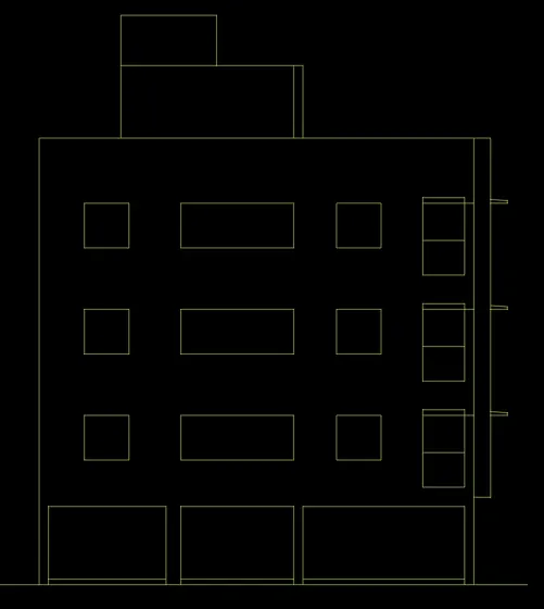
- Using line tool and offset tool draw the balcony chajja and balcony railing.
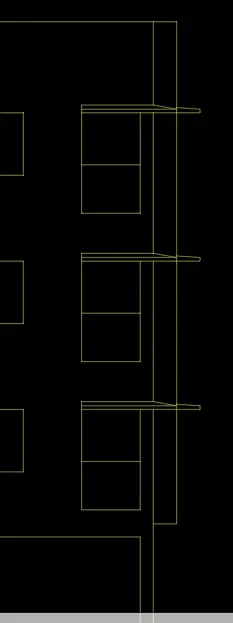
- Assign all the objects drawn to its respective layers by going to layer properties.
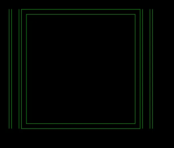
- Using offset tool draw the window chajja portion which is outward from the wall.
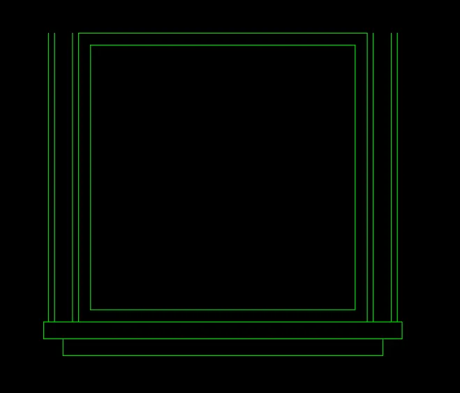
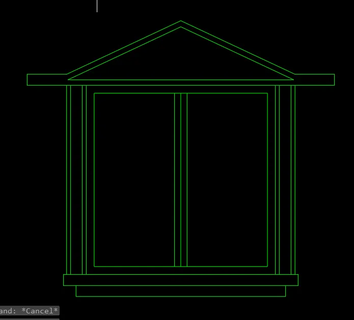
- Using Arc tool draw the curve in the chajja.
- Assign all the objects in the chajja portion to chajja layer.
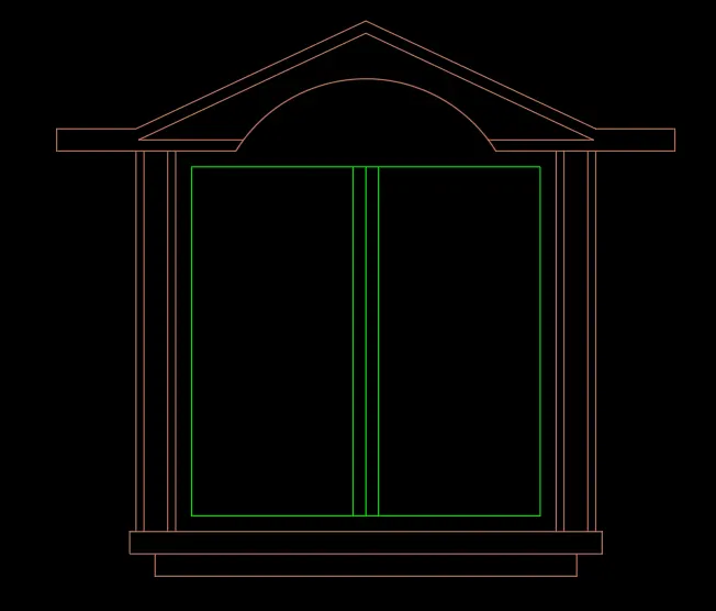
- Using offset tool, line tool and arc tool draw the other windows chajja and extensions.
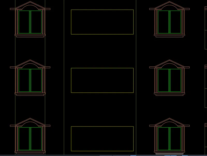
- Type 'Hatch' and select 'Gost_glass' and click on the area to be hatched.
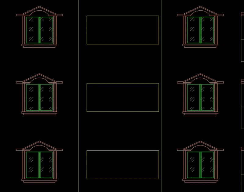
- Go to hatchedit and adjust the scale.
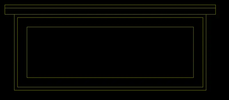
- Using line tool and offset tool draw the chajja portion of the verandah.
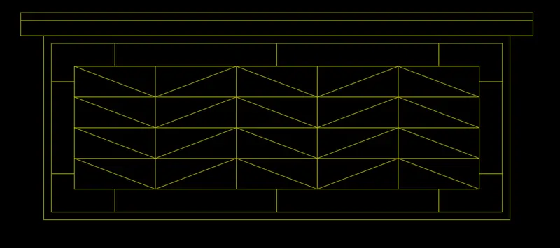
- Go to layer properties and create a new layer 'Iron_grill'.
- Assign the chajja object to the chajja layer and iron grills to its corresponding layer.
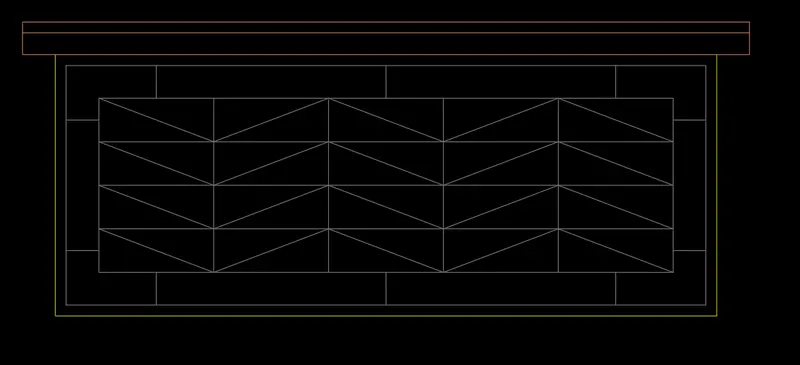
- Follow the same procedure for other verandah portion.
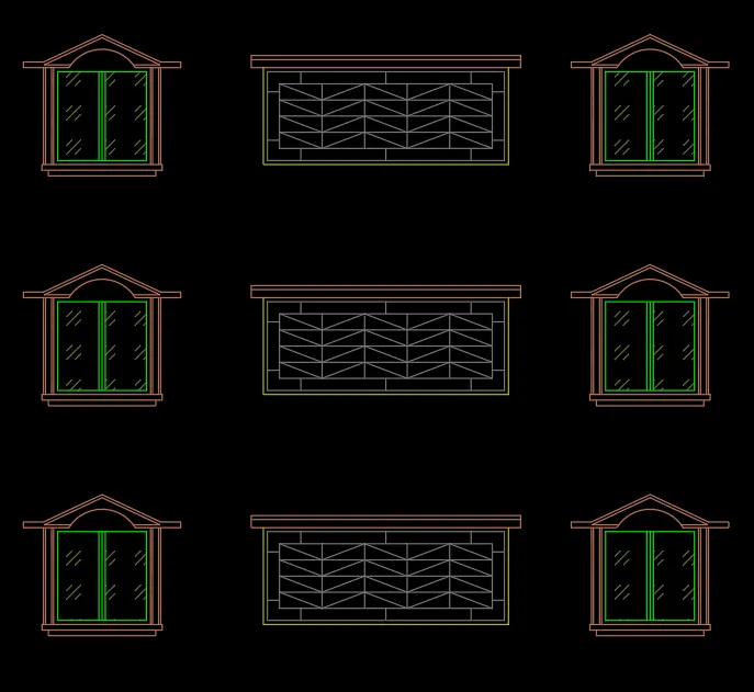
- Using line tool draw the balcony railing.
- Also assign the objects to corresponding layer.
- Using path array draw the railings.
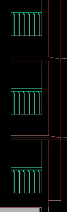
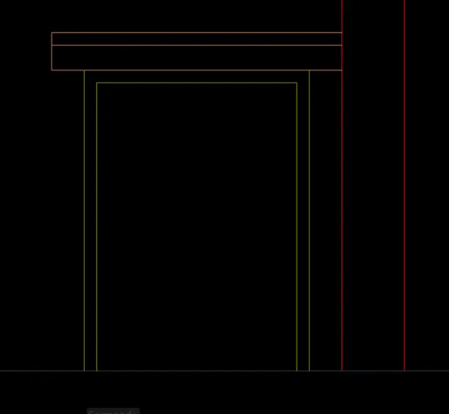
- Using line tool and offset tool draw the door on the terrace part.
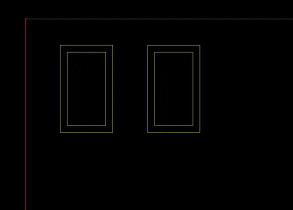
- Draw the other portion of the drawing using line tool.
- Using mtext command assing the texts wherever required.
RESULT:
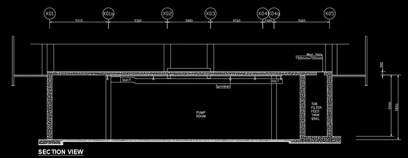
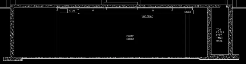
AIM: Create the sectional view of an industrial building and provide appropriate hatches and dimensions wherever required using AutoCAD.
INTRODUCTION:
AutoCAD is a commercial computer-aided design (CAD) and drafting software application. Developed and marketed by Autodesk, AutoCAD was first released in December 1982 as a desktop app running on microcomputers with internal graphics controllers. Before AutoCAD was introduced, most commercial CAD programs ran on mainframe computers or minicomputers, with each CAD operator (user) working at a separate graphics terminal. AutoCAD is also available as mobile and web apps.
AutoCAD is used in industry, by architects, project managers, engineers, graphic designers, city planners and other professionals.
PROCEDURE:
Step 1: Open AutoCAD by clicking on the AutoCAD icon on the Desktop
Step 2: Start a new project by clicking Ctrl + N on the keyboard. A "Create new drawing" dialogue box will appear.
Step 3: Choose 'metric' and click OK.
Step 4: Commands used are as follows:
- Type 'L' for line tool and click anywhere in the screen to specify first point.
- Now type @25750,0 and press enter
- Type 'O' for offset tool and specify offset distance as 300 and offset the line draw in downward direction.
- Similarly using offset tool offset the previously drawn line at a distance of 5850 downward.

- Using line tool draw a line joining end points of the horizontal line.
- Using offset tool offset the line drawn at a distance 450
- Using offset tool draw an offset of 1000 from the mid point of the column previously drawn.
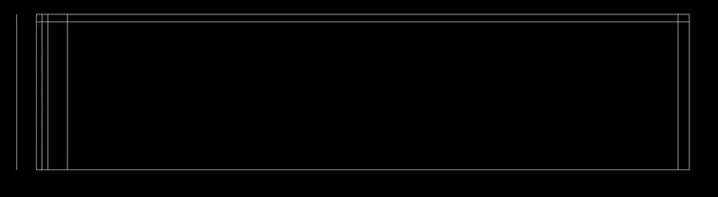
- Stretch the bottom line and meet it to the vertical line in the left side.
- Using offset tool offset the right second vertical line at distance 2000 in the left side.
- Offset the previously drawn line at a distance 450 in the left side.
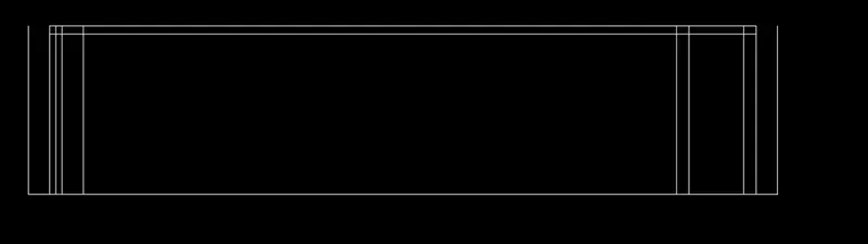
- Using offset tool offset the bottom horizontal line at a distance 25,100,50 downward.
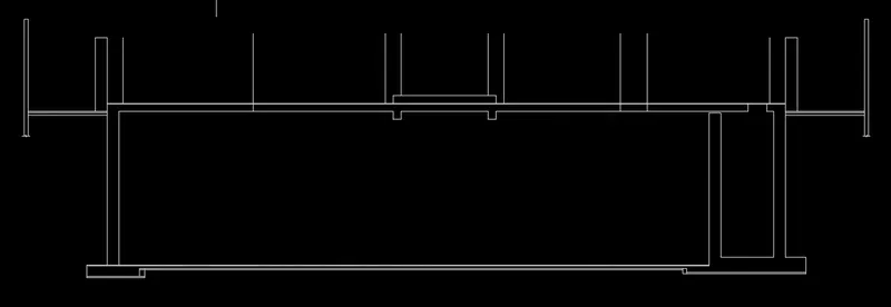
- Similarly using offset tool and using assumed dimensions draw other aspects of the drawing.
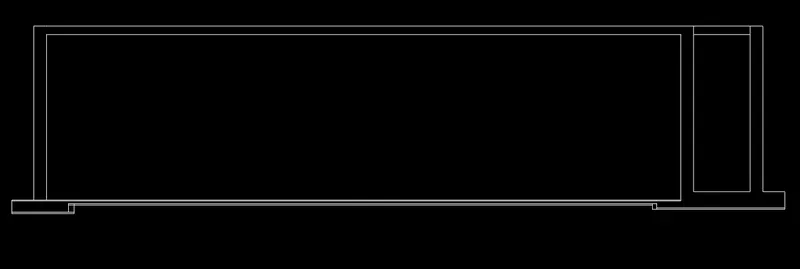
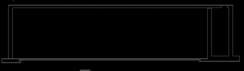
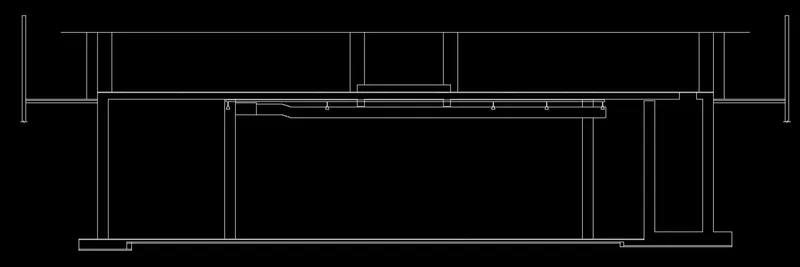
- Now using line tool draw the Duct, Fire Pipe etc., and using trim tool modify the drawing.
- Use 'E' command to erase the unwanted lines.
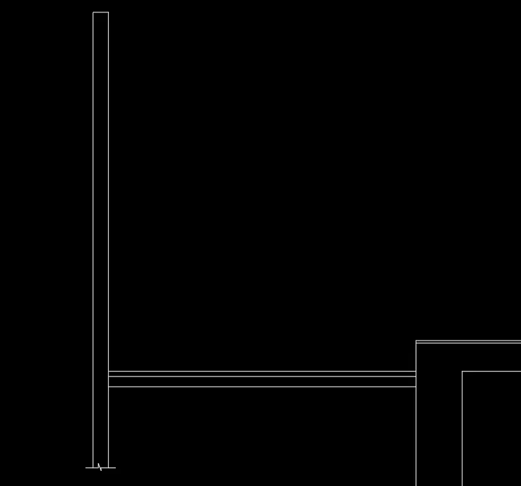
- Type 'C' and draw a circle of radius approx 500mm.
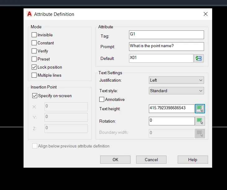
- Now type 'Attdef' to define attribute.
- Fill the tag, promt and default name and also define the text height.
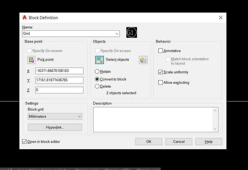
- Type 'B' for block creation.
- Specify the base point and the select the object and press OK.

- Using Dimlin tool assign the dimensions wherever required.
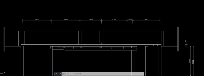
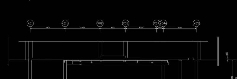
- Type 'i' to insert block which was previously created.
- Drag the block to the respective position and edit the attributes as per the drawing.
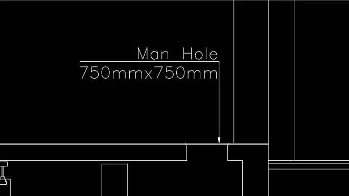
- Using Multileader tool annotate the required region.
- Similarly using mtext command assign texts wherever required.
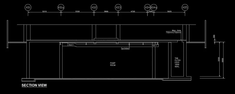
- Type 'H' to invoke hatch tool.
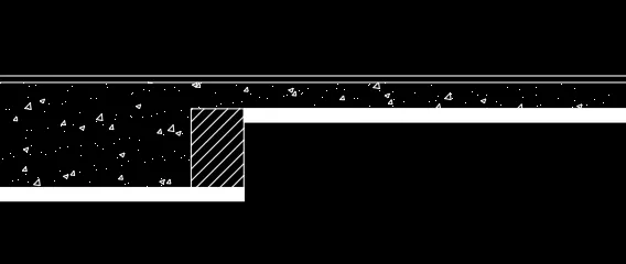
- Select 'AR-CONC' and adjust the scale.
- Click on the area where concrete hatch is to be done.
- Again type 'H' and select 'Solid' and click on the area where hatching is to be done.
- Again type 'H' and select 'ANSI-131' and click on the area where hatching is to be done.
RESULT: