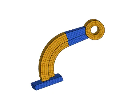
Assignment 2
Aim: To create a proper hexa and tetra mesh fro the given component and edit the engine file0001.rad by entering the values after calculations.
calcluations part:
1. Check the material properties of the rail component and calculate the speed of sound in steel rail=_______
Ans: The material property mentioned in the file is Steel.
For calculaion of the speed of rail
formula:c=(E/density)^1/2 (unit conversion:= mm/ms=1000*m/1000*s)
=((21*10^4)/0.0078) (c=m/s )
=5188.74m/s
2.The length of the rail is about 1000 mm.calculate the time takes for a shock wave to travel from one end of the rail to the other.
Ans: given=l=1000mm
formula:t=l/c
=1000/5188.74 (ms) (unit conversion=mm/(mm/ms)
=0.192ms (t=ms)
3.Time for sound to travel length of rail=______
Ans:t=0.192ms
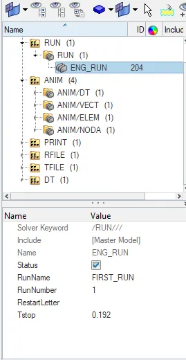
4.Edit the engine file so that the stress wave can be monitored, moving from one end of the rail to the other during impact -this will require a termination time equal to the time it takes for the sound to travel the length of the rail(set on/RUN card)
Ans:Extract the engine filee0001.rad in hypermesh.
Go to cards-engine run and their we can edit the time travel value i.eTstop= 0.192ms
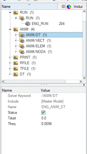
5.Set the frequency of animation output to a time that will give 20 animation steps(/ANIM/DT)
Ans:In engine file0001.rad edit the animation file, change the vaule of T frequency
tfrequency=T/no of animation steps
=0.192/20
=0.0096ms
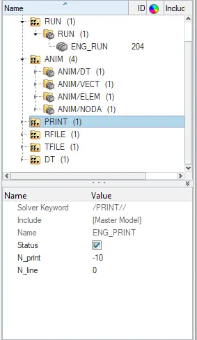
6.Change /print -10.
Ans:In engine file0001.rad we will have a pint option change the value to -10.
7.
1.housing
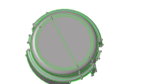
CAD image:
Procedure:
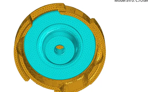
Import the model check for the errors in the model.
Create a mesh using F12.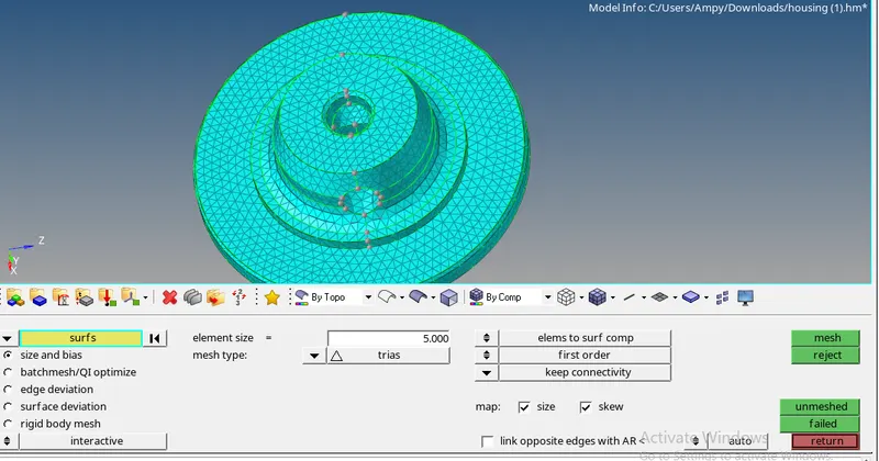
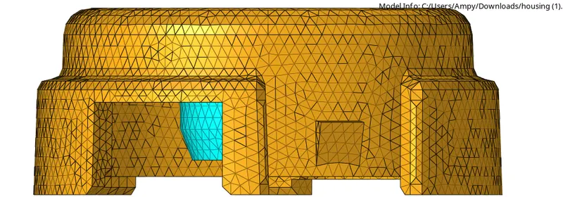
Go to 3D-tetra mesh-select the component-go to mesh parameters
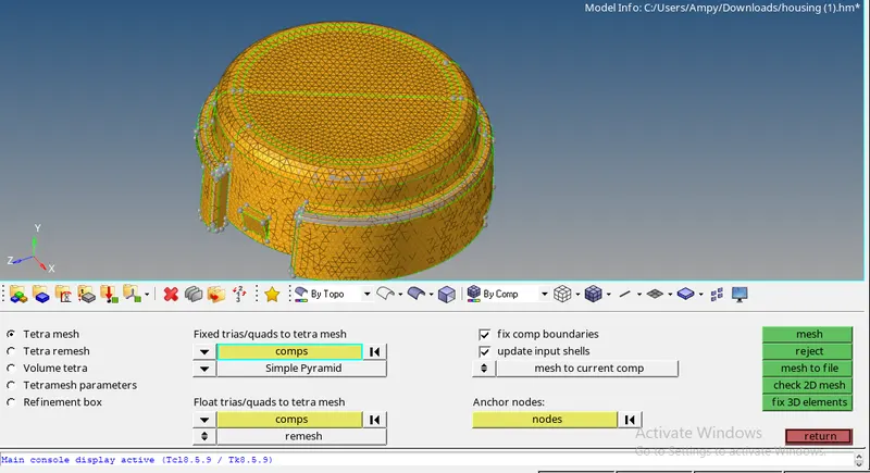
select the min tetra (if possible)-edit the tetcollpase value and go back to tetra mesh and click ok.
Check for the tetcollpase failure.
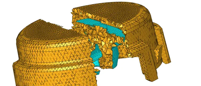
If there is failure remesh the elements.
Final image of the model:
2.Arm
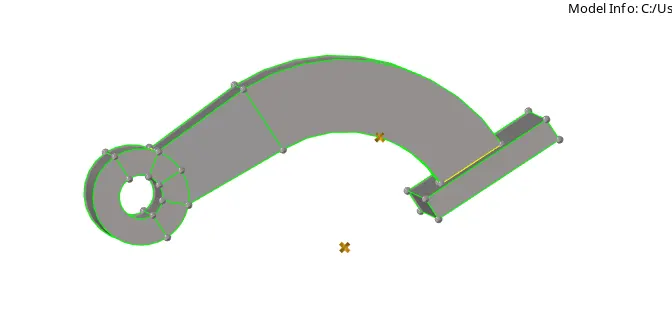
CAD image:.
Procedure:
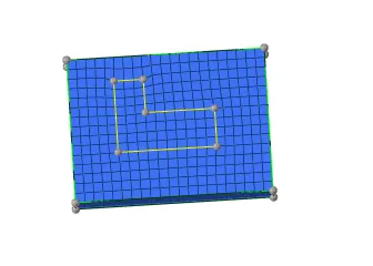
For base-create 2d mesh using quads-3D-elemnt offset

select the elemnets to offset-destination surafce-enter the offset value-total thickness
click offset+ -all the elemts are craeted till the lower surafce.
For arm curve-slect the 2d elemts of the arm use spine option in 3D
select spine-select the elements to be spined -set the angle to 90
create a centre of rotaion and then select the x axis and the base as centre of rotation and then set the value of on spine to 25
click offset- and check whether all the elelments are offseted .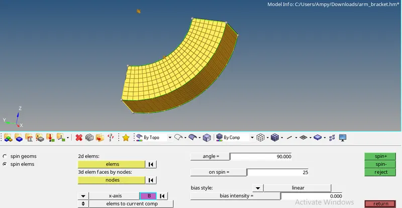
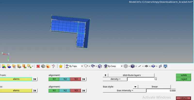
Arm Straight-create a face using arm curve-hide the mesh of the arm curve
Create a 2D mesh on other side of the face-mainatin same number of elements on both the sides
Go to 3D-linear solid-select the elemts on face and next select the elements on the other face
Now select the aligmnet on both the faces( remember to select the same elemnt on both the face)
click solids ok
BOSS-Create a 2D mesh on the face of the model and edit the mesh so that there are proper quad elements
create a node according to the last arm so that we can get a proper mesh flow
Go to 3D- solid map-select the elemts to be dragged and then fill up all the other parameter.
click mesh and check all the mesh produced is correct.
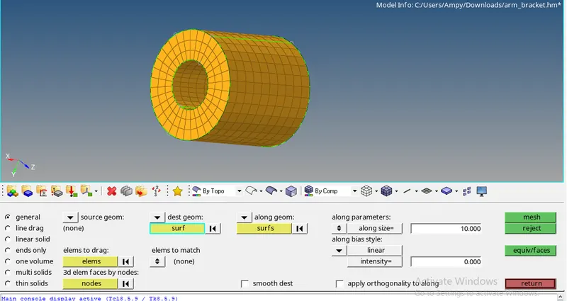
Now delete all the 2D elements in the model by using delete-config-quad4 elemts-save it
Final image of the model: