Project 2
INTRODUCTION:
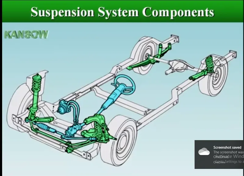
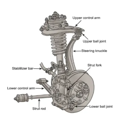
Automotive susepnsion assembly is a part of car model which helps the body to avids shocks and helps in proper running of the vehicle.Here it is very important to anaylse the model with static and dynamic load.
The rear suspension of a vehicle performs the same general function as front suspension, but the specific construction is typically quite different. The most basic purposes of a suspension system are to prevent the body of a vehicle from hitting the ground and to keep the tires in contact with the road
AIM:
To discritsize the parts seperately and deploy a proper mesh .
To ensure the proper connection between the parts.
PROCEDURE:
Import the model to Ansa
Conduct a geometry check and rectify all th errors.
Measure all the thickness of the parts
Seprate the parts and assign seprate PID to each part.
For same cross sectional part produce a midsurafce and mesh using proper qaulity criteria.
And for the remaining parts whose Cross scetion is not the same conduct a tetra mesh and assign a SOLID PID to each part
Ensure all the qaulity is cleared.
Save the model.
STEPS:
Import the model
Check for the goemetry clean up after analysing the model.
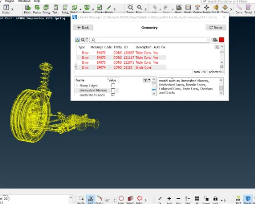
Give a complete TOPO to the model.
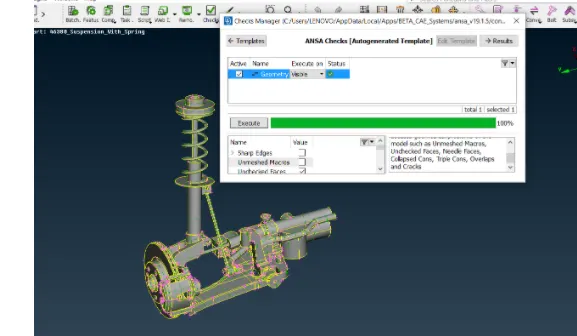
Disassemble the model according to parts available and give it a seprate PID
Suspension system:
As the suspension parts have same crosssection area so we are producing a mid for these components .
check the dimension then use offset command to offset the topsurafce mention the dimension and save it
enter the quality criteria
Quality criteria for Mixed elements (For Midsurface only):
|
S.No |
Quality Criteria |
Value |
|
1 |
Target/Average length |
4 |
|
2 |
Minimum Length |
2 |
|
3 |
Maximum Length |
6 |
|
4 |
Aspect |
3 |
|
5 |
Warpage |
15 |
|
6 |
Skewness |
45 |
|
7 |
Jacobian |
0.7 |
|
8 |
Minimum Quad Angle |
45 |
|
9 |
Maximum Quad Angle |
135 |
|
10 |
Minimum Tria Angle |
30 |
|
11 |
Maximum Tria Angle |
120 |
use spotmesh command to produce a mesh and check for the quality criteria and solve the errors
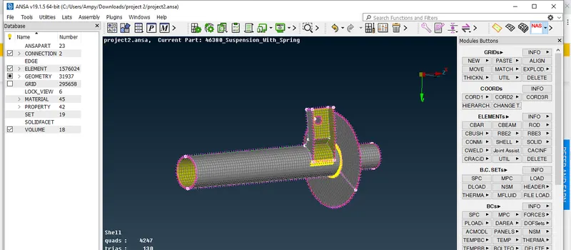
follow the same procedure for all the remainig components.
Tera mesh:
select the tyre and RIm model and check for the geometry clean up
then select the spot mesh and ortho tria for curve surfaces and mesh the component.
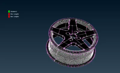
check for the quality criteria and then save it
go to volume mesh-define the part-go to list-remesh the part.
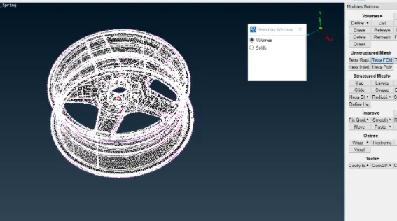
check for the telcollpase and sove the errors manually or use fix command.
the set a seprate PID to the component and save it
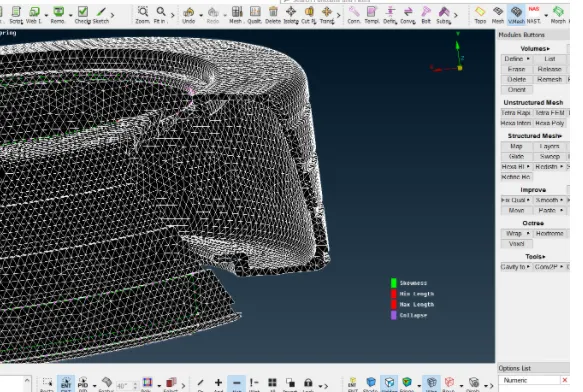
Follow the same procedure fro all the other components in which tetra mesh is to be produced.
COIL:
select the coil and produce a curve using the middle option.
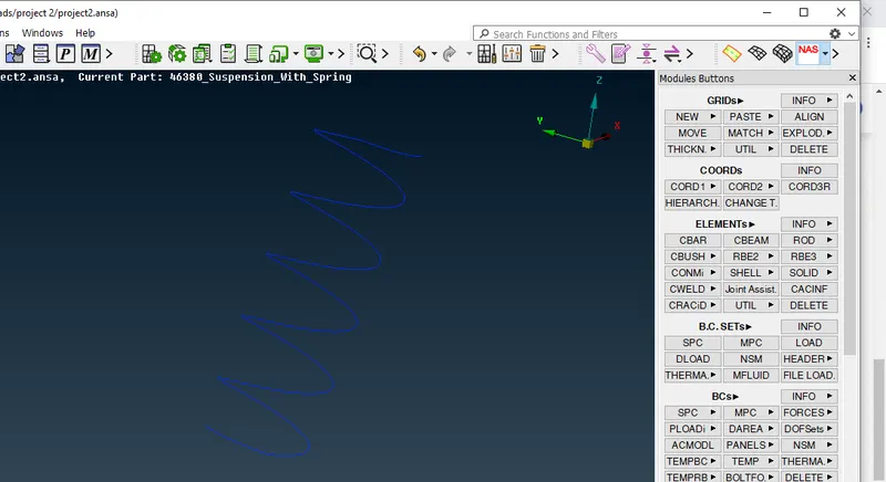
join the complete coil using connect option
by using CBAR we have to selct the orientation node and select the box type
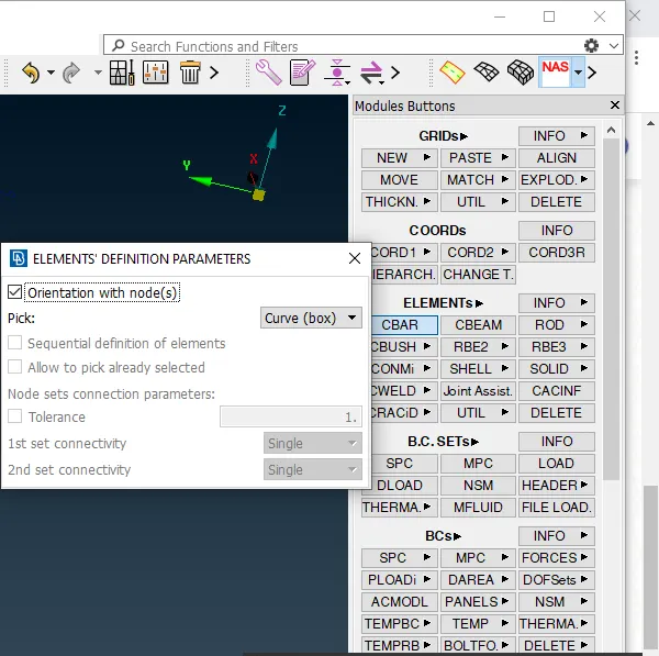
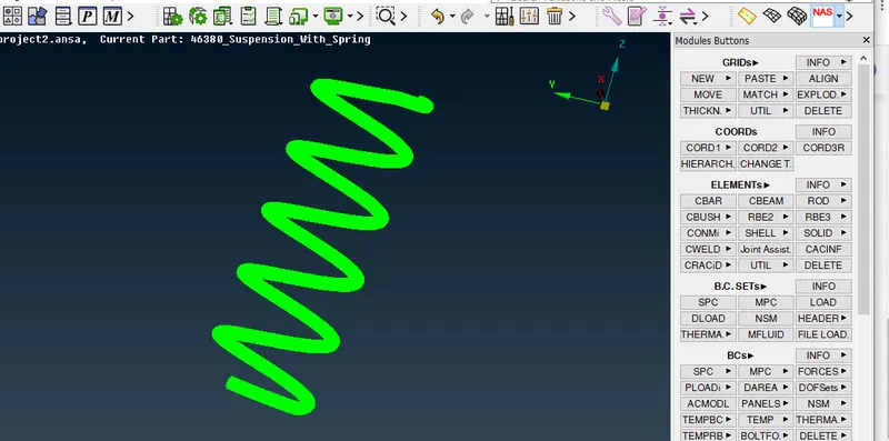
press ok and we will have a solid produced for the shell once we convert the elemnets into solids.
FINAL image of the product:
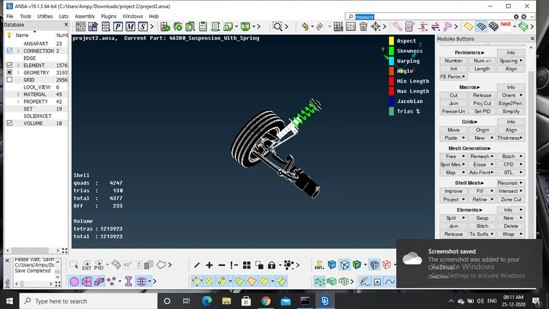
RESULT: Proper mid is produced, mesh is generated , also the tetra mesh has less quality criteria and has a very good feature caputring.