Week 1 Stress Concentration on a Plate with hole
Aim:To anaylse the stress concentartion a plate with hole
Case1:
Open the ansys workbench,set the dimension to mm,kg,KN.
Select structural analysis>>set up engineering data by selecting the material required for the part>>right click on geometry>>open spaceclaim>> create a diagram according to the question given.
Initially create a rectange set up the dimension length=300mm and height=120mm >>using concentrated lines draw horizontal and vertical lines so that we get a centre plane>>create a hole at the centre of dia=60mm>>close the editing panel
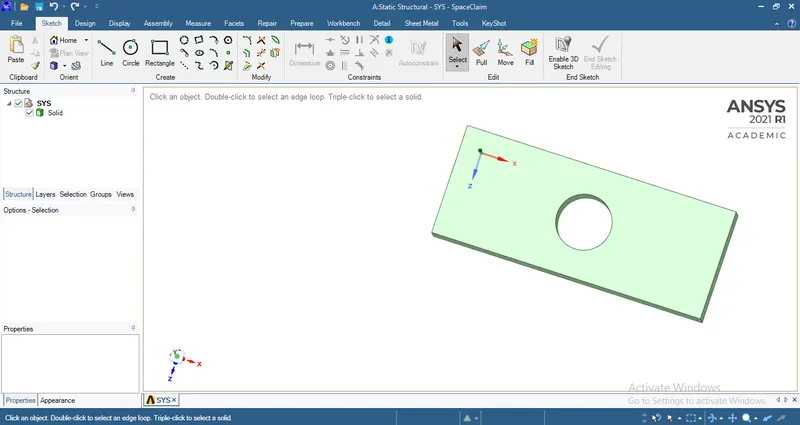
To assign the thickness>>select the pull option>>select the face and pull in particular direction>>set the dimensions t=30mm>>on the right side of the screen we have a panel where the curve is available, delete that and close the space claim screen.
The model is been updated.
Model>>right click edit>>mechanical screen is been opened>> we can see that the same figure is been diaplayed>>check for the material>>coordinate sysstem>>mesh>>right click create>>method>>In method panel >>select the body and apply>>change methods to tetrahedron>>then change the element size to 5mm>>go back to mesh and genertae mesh>> we can see the mesh is been deployed.
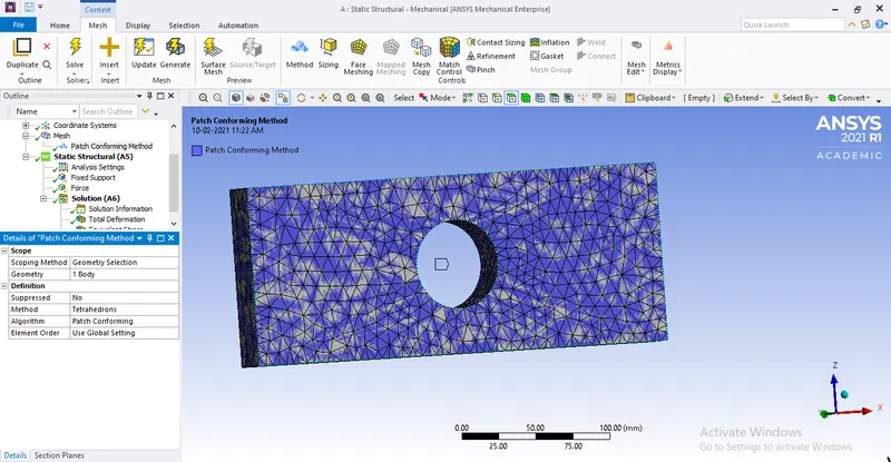
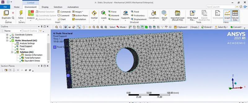
Structural anaylsis>>right click create>>fixed body select the left side of the model
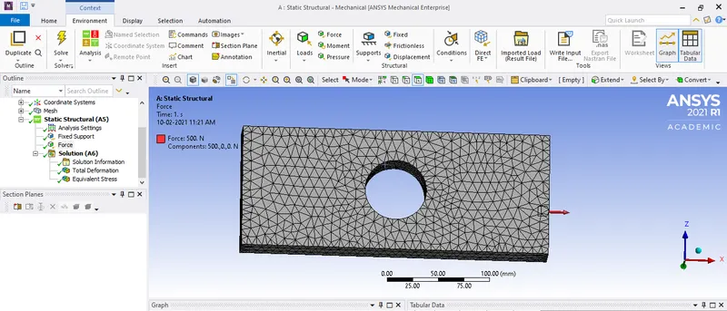
Structural anaylsis>>right click create>>again create force>>select the right side of the model>>check in which direction the model is to be streched>>(+)x direction>>change the vectors to as components>>select the x and mention the value as 500N and then save it
Go to solution>>right click create total deformation and von misses stress.
Right click on the structural analysis and then solve.
compare the results
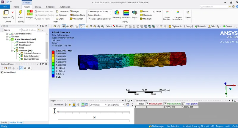
Total deformation:
max:0.00027mm
min:0 mm
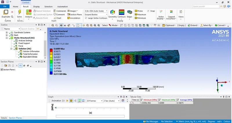
von misses stress:
max:0.6809 mpa
min:1.33*10^-2 mpa
Case2:
Open the ansys workbench,set the dimension to mm,kg,KN.
Select structural analysis>>set up engineering data by selecting the material required for the part>>right click on geometry>>open spaceclaim>> create a diagram according to the question given.
Initially create a rectange set up the dimension length=300mm and height=120mm >>using concentrated lines draw horizontal and vertical lines so that we get a centre plane>>create a hole at the centre of dia=60mm>> create a random hole on the central horizontal line of dia=30mm and set the length from centre is 90mm and repeat the same for the other side>>close the editing panel
To assign the thickness>>select the pull option>>select the face and pull in particular direction>>set the dimensions t=30mm>>on the right side of the screen we have a panel where the curve is available, delete that and close the space claim screen.
The model is been updated.
Model>>right click edit>>mechanical screen is been opened>> we can see that the same figure is been diaplayed>>check for the material>>coordinate sysstem>>mesh>>right click create>>method>>In method panel >>select the body and apply>>change methods to tetrahedron>>then change the element size to 5mm>>go back to mesh and genertae mesh>> we can see the mesh is been deployed.
Structural anaylsis>>right click create>>fixed body select the left side of the model.
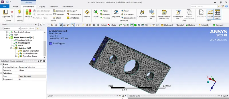
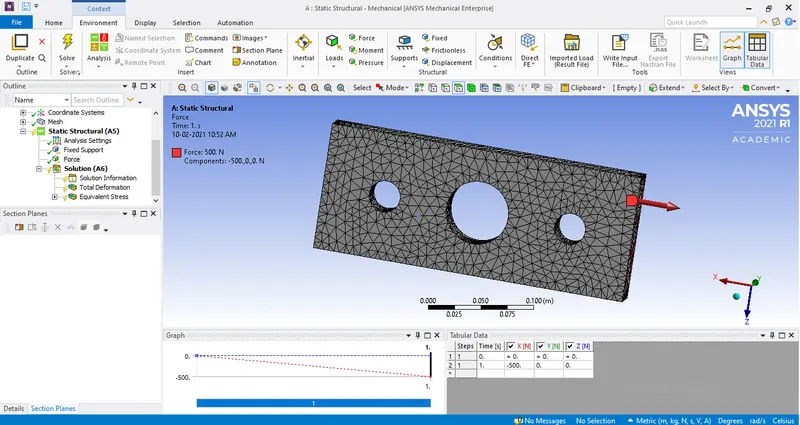
Structural anaylsis>>right click create>>again create force>>select the right side of the model>>check in which direction the model is to be streched>>(-)x direction>>change the vectors to as components>>select the x and mention the value as -500N and then save it
Go to solution>>right click create total deformation and von misses stress.
Right click on the structural analysis and then solve.
compare the results
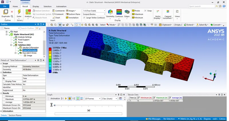
Total deformation:
max =2.98*10^-4mm
min=0mm
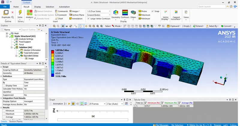
Von misses stress:
max=0.58958 Mpa
min=3.370*10^-3 Mpa
Results:
case1 case2
stress max 0.6809 mpa 0.58958 Mpa
stress min 1.33*10^-2 mpa 3.370*10^-3 Mpa
max displacement 2.98*10^-4mm 0.00027mm
min displacement 0mm 0mm
Based on the above analysis we can see almost same results in both the models but there is difference in the stress generated. As we know that the stress plays an important role in maufacturing.Hence the model having min stress is been considrerd.
From the above results we get to know that the case1 has more stress formulation than the case2.
Hence in the manufacturing point if view,the best model would be case 2(plate with three holes) because the stress generated is minimum and the chances of the model getting failure is less when compared to the case 1.