Assignment 6
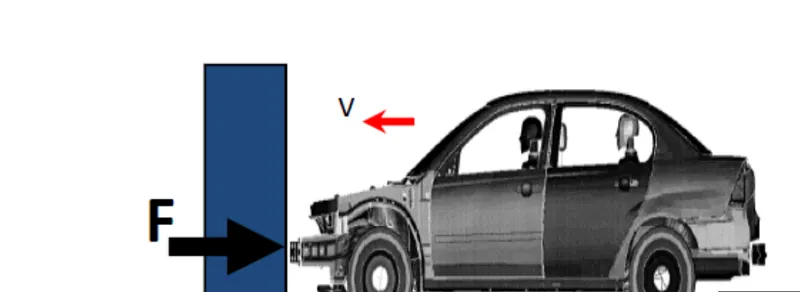
A crash test is a form of desrtuctive testing usually performed in order to ensure safe design standards in crash worthiness and crash compatiblity for various modes of transportation or related systems and components
Abstarct:
An automoblie(car body structure) was designed and analyzed which can be used for travelling of th epassengers and goods. the car body structure is made of aluminium and the crash analysis is performed onn the car structure to knoe how the car body structure deforms in a crash accident. crash analysis is performed on car body design for ensuring safety of passengers in accidents. A detailed car bodly deformationb analysis has performed in hypermesh and radioos and hypercrash.
PROCEDURE:
1) Import the given model into hypermesh workbench.
-go to solver deck and select the file location
-click on import button.
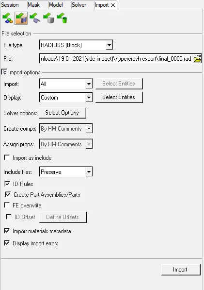
-model will be displayed in the hypermesh graphics area shown below
Case setup and execution:
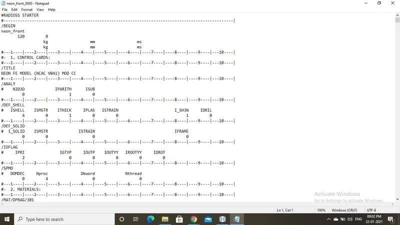
1. check the unit system by openeing the 0000.rad file in notepad
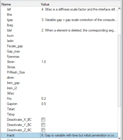
2. create appropriate interface, friction 0.2 and recomended parameters
In this case Type 7 contact interface is defined. TYPE7 (Multiusage impact interface) creates contact between master surface and slave nodes
define all the recomended values
select all the slaves nodes and all the master nodes of the whole model.
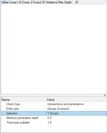
3. make sure no penetration and intersections in the model
So before running the stimulation we need to check whether the model has penetration and intersections if there then remove.
now there are no penetrations in the surface.
4. Create a rigid wall awith friction 0.10
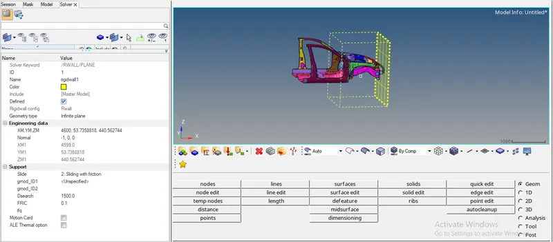
In this we are having a side impact so we have to select a cylindercial type of rigid wall
steps:
-go to solver browser>right click>create>Rwall
-select the type of rigid wall>CYL
-enter the co ordinate of nodes where the rigid wall is to be created (in front of the front door)
-define search distance for slave nodes(1000)
-enter COF-0.10
5) Compare the model weight with the referance model and use added masses to reach target weight 700kg while getting CG about the required range.
To find COG go the Tools>mass details>COG.
Present weight of the model is 188 kg
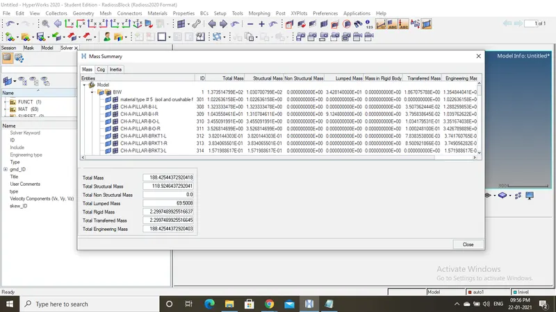
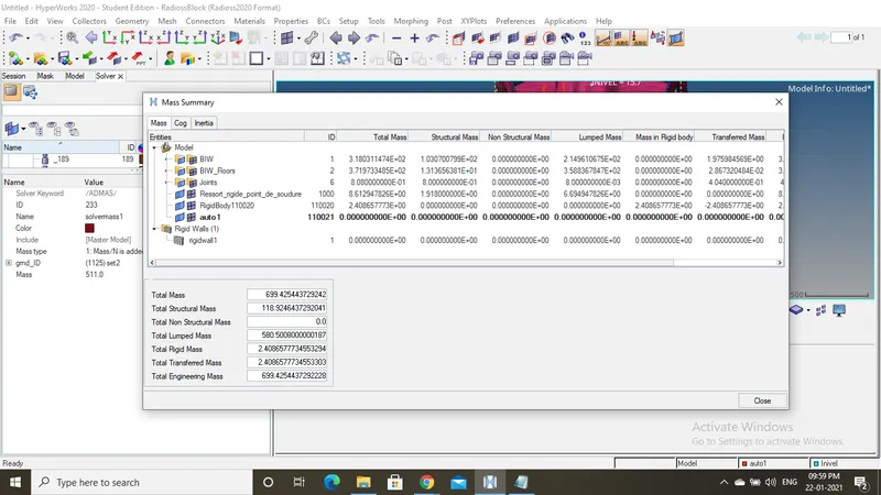
So we need to add masses considering the weight to driver and co passenger as 100KG each and gear propeller as 150 and other other weight as 90 kg
So totally we get 700 kg and that COG is loacted exactly at the centre.
-go to solver>admass> select the Grnd_id>right click>slect node where load is to be added and put the value of mass to be added and then select type1.
Follow the same steps until you get the masses as 700kg
check for the COG point whether it lies in the centre of the model.
6. Initial velocity 35mph
So to move the vehicle we have to move the model with some velocity.
so the value is in (miles per hour) convert it to mm/sec
1mile=1.609 E66 mm and 1 hour=3.6E6
so we get the final value as 15.64 mm/ms
steps:
-Go to solver-right click>create new> boundary conditions>inivel
-select Grnd_id>right click>all nodes (because The vehicle needs to move completely)
-velocity conponents set value for Y direction as(15.64)
-then the initial velocity is added
7)Sectional force in th rail member,gunshot and A pillar
Define a cross section is actually to check how much forces is been produced during the impact.
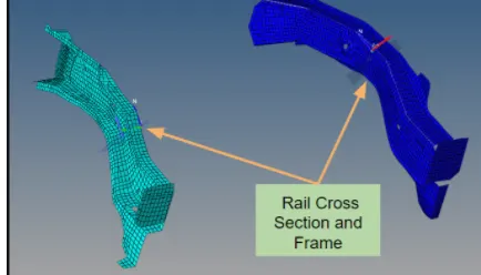
cross rail
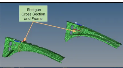
Gunshot
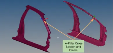
Steps:
Go to solver>right click>create new>section.
select the three nodes-N1>N2>N3.
set the value of delta-0.1,aplha-0.67 .
select the Grshell elements where the section is to be formed.
To create a frame >create a new movable frame.
select the origin nodes- select Z-axis and then select a node in Z axis and other node for plane in Yz plane and set the relative value to 25 and click create.
Now assign the frame to Cross section in section block.
(Note: the frame should be always be perpendicular to the surafce where the frame is created)
8)Intrusion at B pillar,hinge pillar and fuel tank region.Provide recommendation on what can help to reduce Fuel tank intrusion.
To create intrustion
Go to 1D>springs> and select the point where the intrustion is needed.
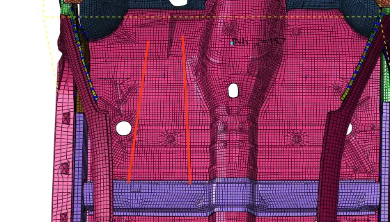
9.
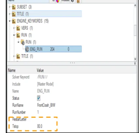
Timestep :0.5 to 0.1 microseconds.
Run 80ms.
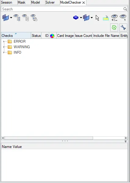
10)Use model checker to ensure good quality.
go to modelchecker>run the error folder.
check if any errors, rectify using the software or try to do manually.
after the check is done go to analysis>radios>slect the path>give it a name with0000.rad file and then (-nt4) and run the stimulation.
RESULTS:
1.Energy and mass error:
open the .OUT file
As the energy error shoulod not exceed above 5%.
and along with this mass error=0.01605
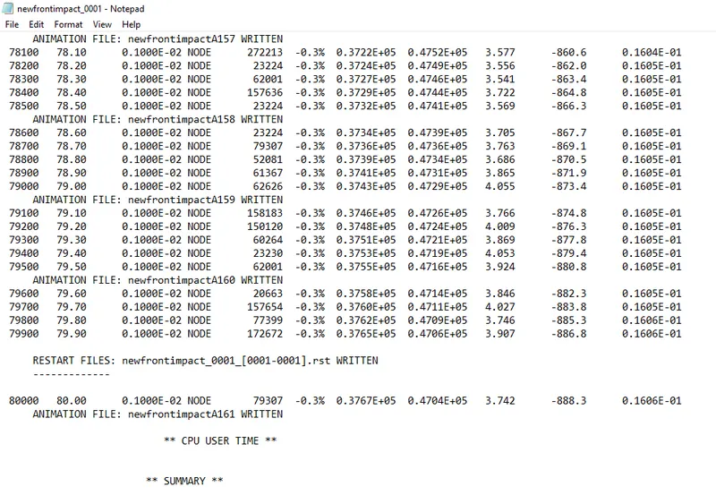
Total elapsed cycle:5786.38 sec
2)Von misses stress
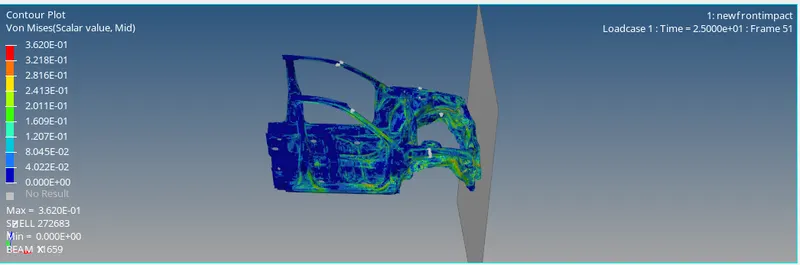
max von misses stress occured is 3.62KN/mm2 at node 272683 .From the Picture we can see that once the car hits the rigid pole,themax stress is flowing from door reggion and transmitted furthur through cross member
3)Displacement:
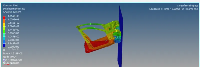
max displacement occured is at node 79904.
4)Energy plot
internal and kinetic energy
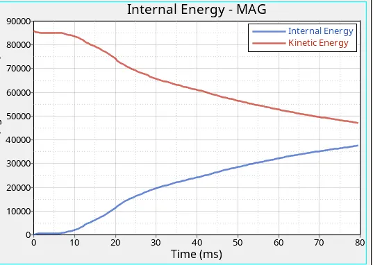
Now here we observe in the energy graph.global energy varaibales for the total energy, kineticenergy, internal energy and hourglass energy has been plotted . The above energy graph shows the change of energu during thc crash.The max kinetic energy of the system is at t=0. It reduces sharply with process of impact.At the same time due to the distortion of the vehicle,which is absorbing the energy the internal energy ascends sharply.Up to the end of impact 90% of the kinetic energy has been transformed to the internal energy of the distorted compnent. At the max deformation the velocity will become zero and thus the kinetic energy will aslo be droping down that means there is no energy to absorb in the system. Thus the internal energy reamins constant thereafter once after the stimulation .
Contact energy and hourglass energy
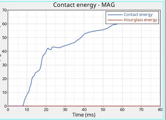
From the above graph we can see that the hourglass energy is almost negligible since we have use improved integrated element formulation. From the graph Hourglass is at 0 and constant through the stimulation contact energy is nothing but the opposite energy generated from the system to avoid the penetration.To avoid the penetration we have to determine the Gapmin value as 0.5. When the car is moving with velocity of 35mph and hits the rigid pole,it starts deformation at the door section and coming in contact with the cross member as evident from the animation hence the penetration of the elements occurs and thus the opposite reaction force also exerted in order to avoid the penetration.Hence the contact energy increasing gradually increases from zero.
Hourglass energy is found from the above graph.Ideally hourglass energy should not exceed 10% of internal energy and the same is also satisfied in the stimulation
5)Sectional forces at gunshot.
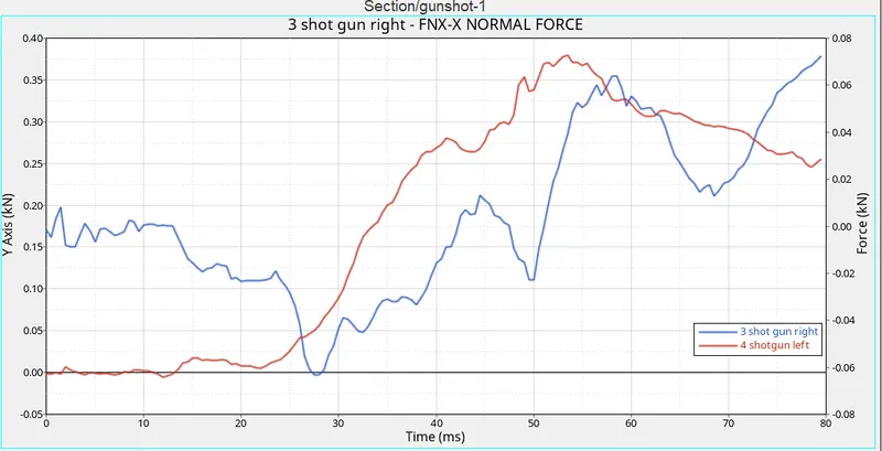
The max cross sectional forces at gun shot right is 0.35kn/mm at t=55ms where as The max cross sectional force at gunshot left RR is 0.38 KN/mm at t=57ms. Once the car hits the rigid wall is the wave is propogating from bumper to the rest of the car through rail ,gunshot and A pillar. From the above graph we can say that the force received at both the section is not different. There is a variatation in the amount of force receiving at the section with respect to time might be because of vibration during the crash. Both the sections are undergoing compression force.
6)Cross section at A pillar
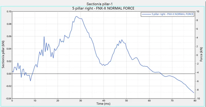
From the above graph we get to know that the force acting on the a pillar is max at the at T=28ms . Initally the force acting on the pillar gets max when it hits the rigid wall, but most of the energy is absorbed by the rail,shot gun and finally the energy is acting on the pillar. so the impact on the pillar is less when compard to other front parts of a car.
5) Axial force on the Bumper :
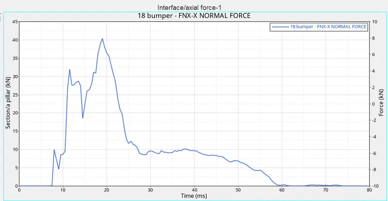
From the graph we get to know that Axial force of 40 KN is max at 18ms. so when the axial force on bumper is max when bumper gets fully impacted into the rigid wall and then the axial force reduces as the kinetic reduces reduces.
6) Accelometer left and right:
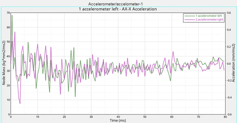
The above graph indicates the accelometer 1&2, these accelometers are placed near the below the Bpillar. Hence these are thewaves that are produced by an accelerometer 1& 2
7) Intrusion on the nodes(66124,1219636)
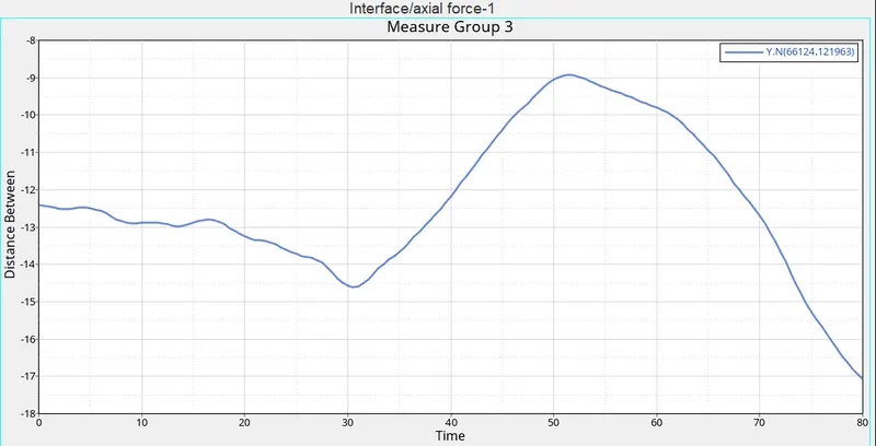
Nodes(66476,122006)
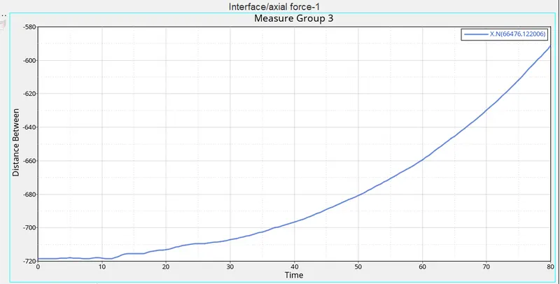
These intrusion are placed near the accelarator and side wall of accelarotar.These intrusions are placed so that whatever the impact takes places in that area, where the drivers right foot and left foot is placed. so to check whether the impact is more or less.
NOTE:
This link provided below is related to the front impact model and file.
https://drive.google.com/file/d/1bSSZCbNxVJpSh7GUBMh4RVWRhfe8VXF6/view?usp=sharing