Advanced Sheet Metal Design Using NX Cad Challenge_2_Box Assembly
Developing a sheet metal box assembly using Nx software
Objective
The aim of the work is to understand the NX software tools (Tab, Normal Cutout, Flange, Break Corner, Bend, Dimple, Bead, mirror, Closed corner, Hem, Unite, Rebend, Unbend, Flat pattern and 2D detailed drawing) and create or develop a 3D model of sheet metal Box assembly.
Introduction
Box assembly mainly used to restore the materials which are used in our day to day life. Sheet metals are the best for developing a box assembly because the cost very less comparing to boxes from casting and another processes. Sheet metal can bend and rebend at different directions with less scrap, cost and manpower is not required more to make a sheet metal product compare to other processes.
Nx software is a simple and easy user guide software and many automotive companies are preferring this software.
Design Methodology / Approach
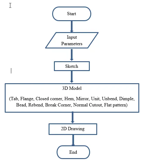
Figure 1: Flowchart of developing of sheet metal casing
Description (Need to explain tools / Features used while designing)
Step by step features are used while creating a 3D model using Nx Software.
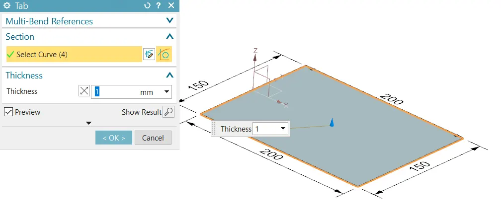
Figure 2: Creating tab feature as a base part
For creating a sketch selected XY plane, drawn a rectangle from center from the origin point with a dimension of 200mm (X direction) and 150 (Y direction) and exit the sketch. Click on Tab feature and select the curve (sketch) and give the thickness value 1mm.
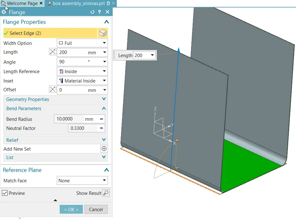
Figure 3: Creating a flange at base part both edges
Both Corners/ edges applied flange at length 200mm, angle 90 degree and radius is 10mm
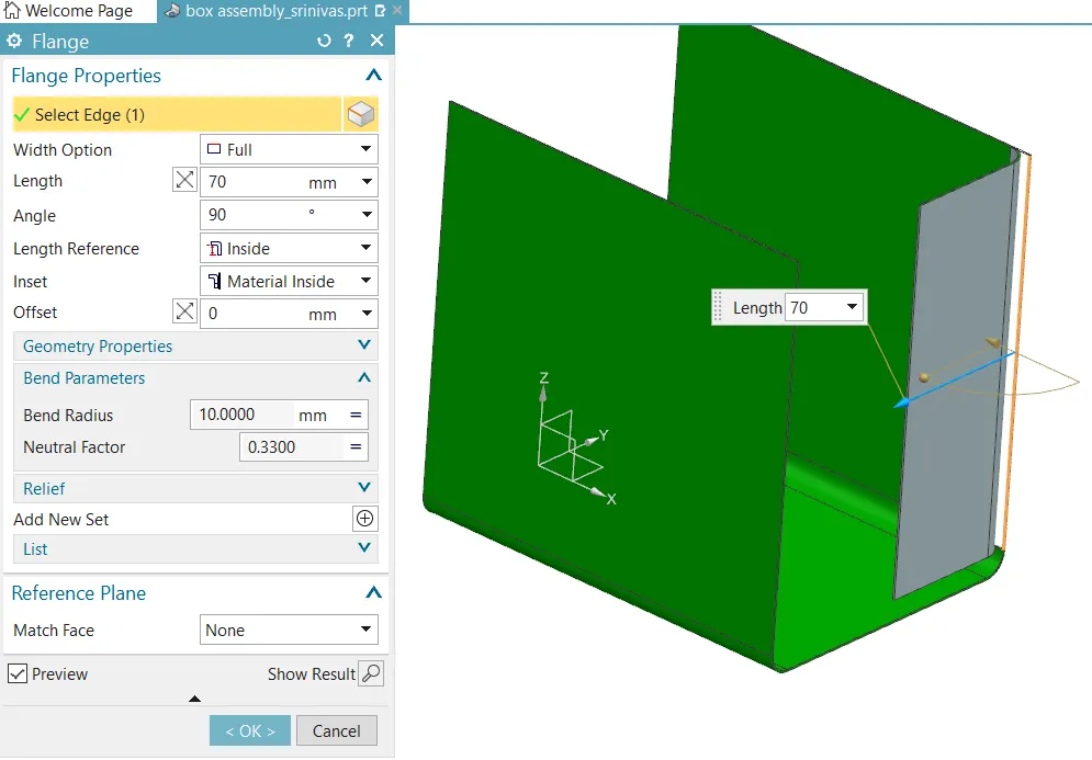
Figure 4: Creating flange at one edge
Again, flange is used at one side with 70mm length, angle and radius are same 90degree and 10mm. Similar way the flange is created at another side
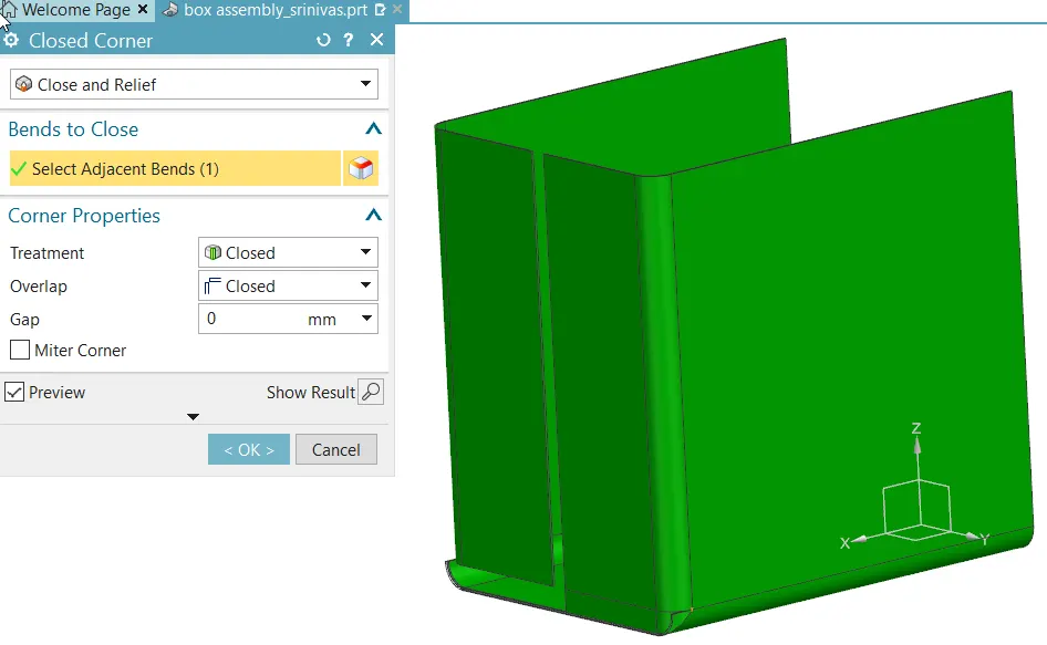
Figure 5: Creating a closed corner
Closed corner is the feature to close the corners where two adjacent flanges meet by extending bend and flange. Similar way another end has to apply closed corner to make complete zero gap.
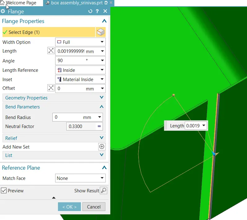
Figure 6: Creating a flange to join and to make hem at one end
Here to make a flange the dimensions are used like length, angle, bend radius is 0.00199999999mm, 90 degree and 0 mm. Similar way another side edge has to select.
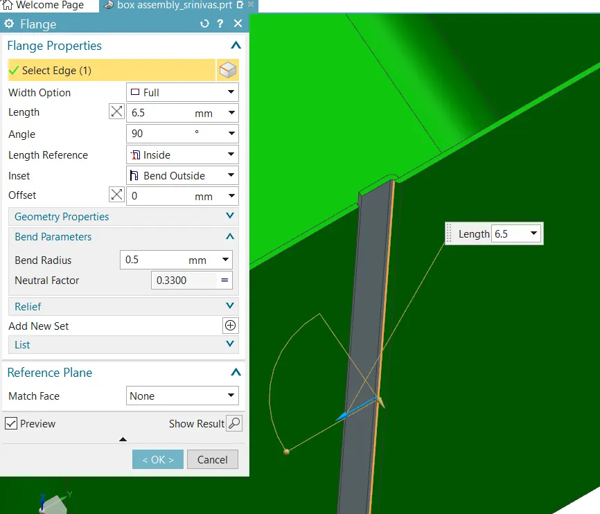
Figure 7: Creating a flange Continuation of Figure 6
Here to make a flange the dimensions are used like length, angle, bend radius is 6.5mm, 90 degree and 0.5 mm. Similar way another side edge has to select.
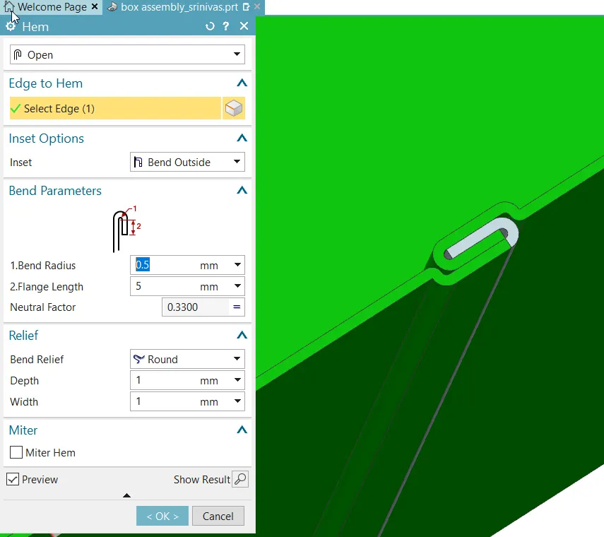
Figure 8: Creating a hem is to join the two flanges
Hem is used at both flanges to make support not to unfold the bend sheets. The values are used to make hem is inset option – bend outside, bend radius – 0.5mm, flange length – 5mm.
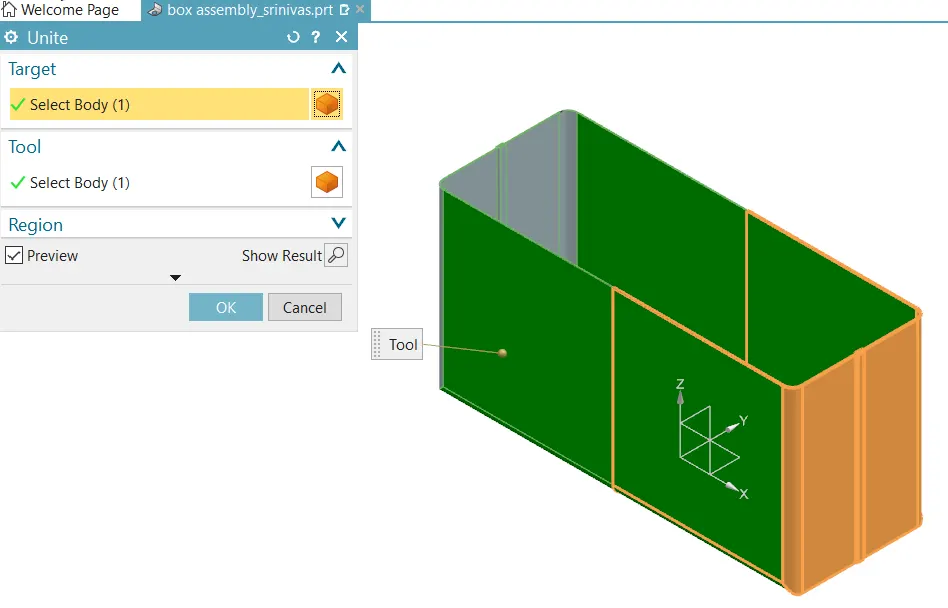
Figure 9: Unite
After completing creating hem the object is mirrored w.r.t to ZY plane then the target body and tool body is joined as a single body by using unite feature.
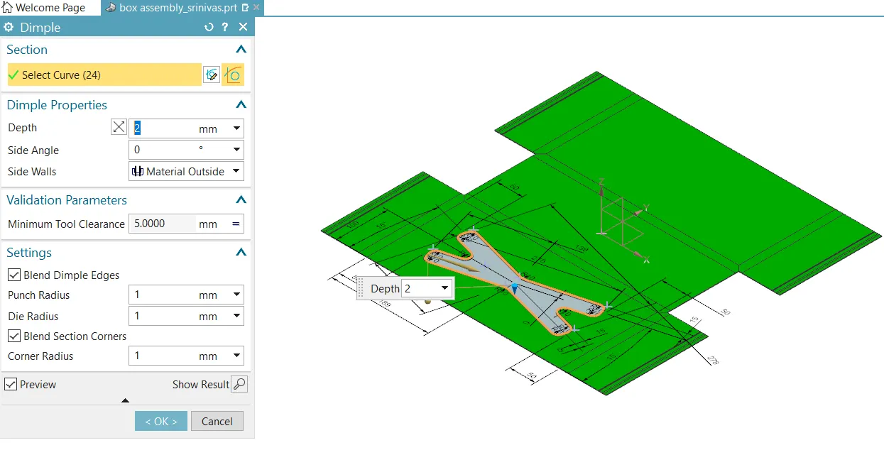
Figure 10: Unbend and creating a dimple at sides sheet
The unite body is unbend and created a sketch on top surface to make a dimple on top surface with depth 2mm then it is mirrored w.r.t to ZX plane.
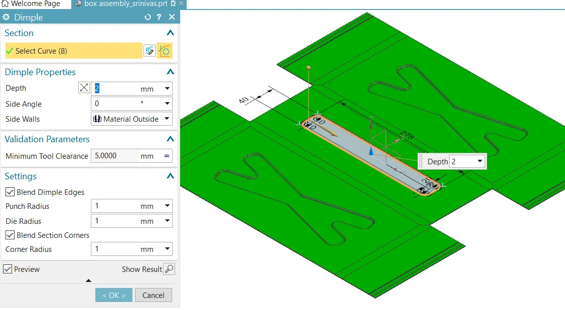
Figure 11: Creating a dimple at middle sheet
Another dimple is created at middle with depth of 2mm.
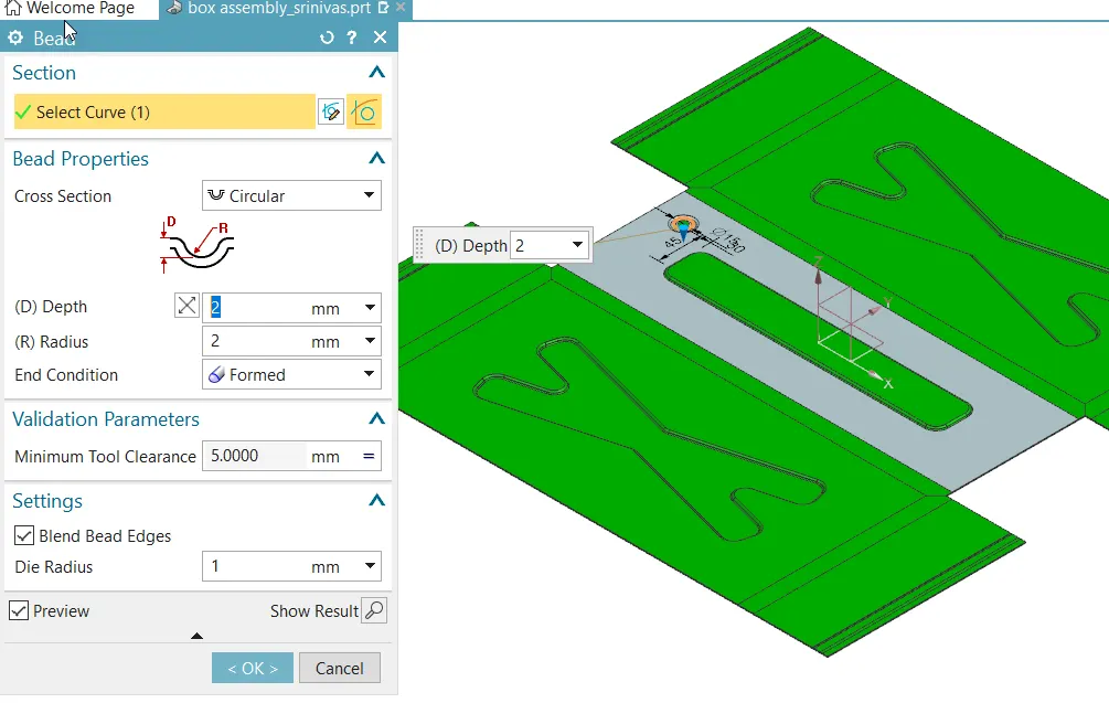
Figure 12: Creating a bead
Created a bead at middle top side with depth of 2mm, radius 2mm and die and punch radius 1mm towards bottom side then mirror the bead feature w.r.t to ZX plane and again mirror the bead feature and mirrored feature w.r.t to ZY plane.
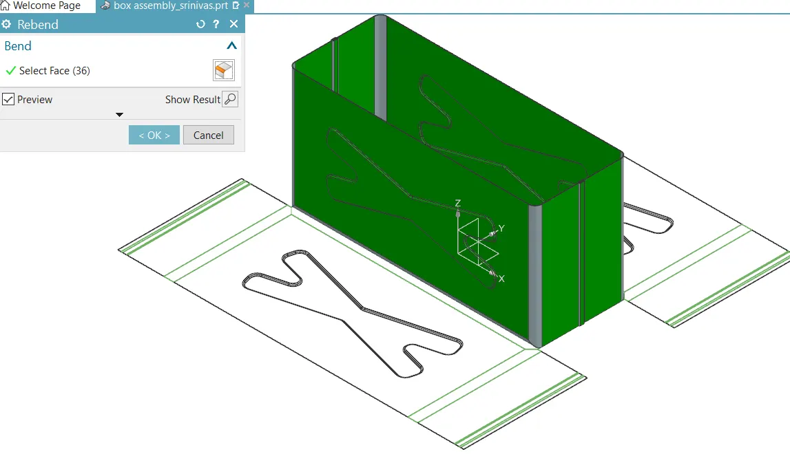
Figure 13: Creating a Rebend
After completing all inside feature just rebend the body to its original bending position.
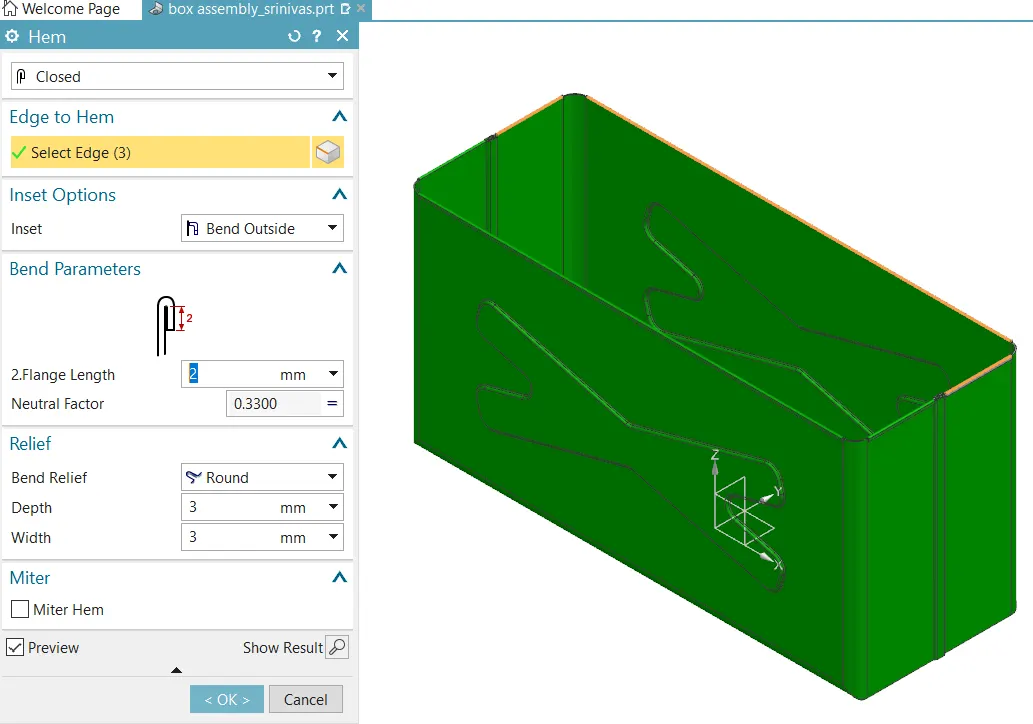
Figure 14: Creating a Hem to grip for top cover
Creating a hem feature at top outside edges with flange length 2mm.
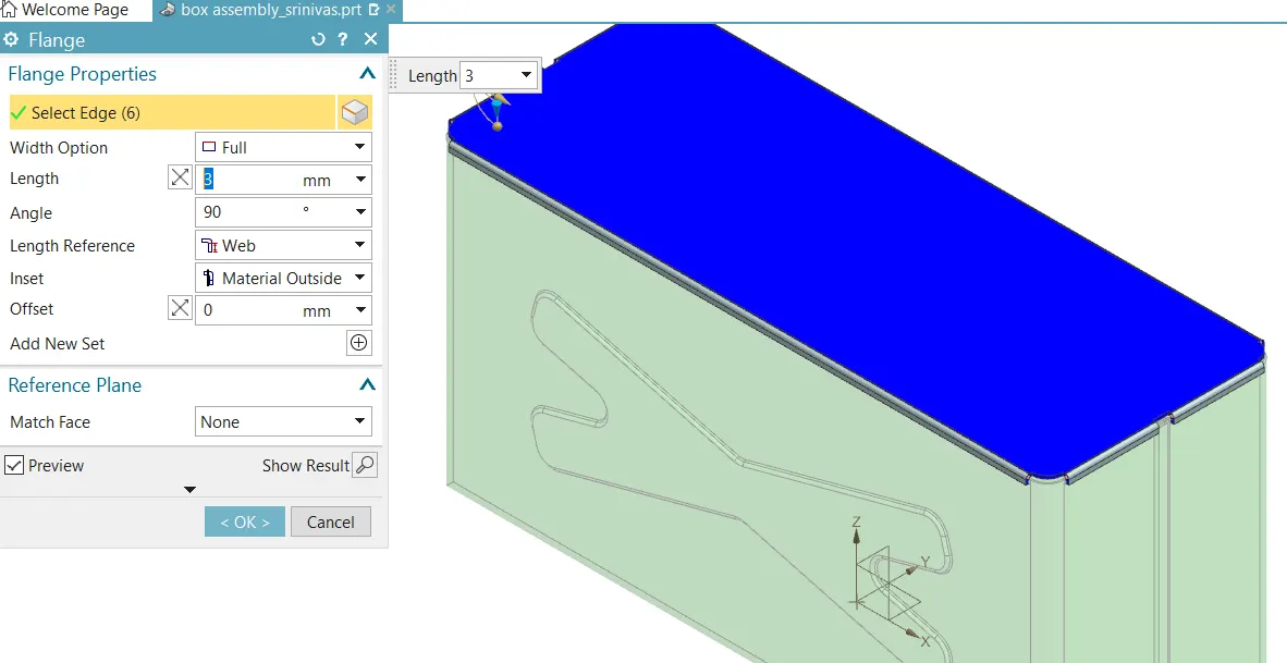
Figure 15: Creating a tab as Cover/Cap
Create a plane at a distance 203mm w.r.t to XY plane to create a top cover/ cap. Then use the flange feature at all edges as shown in above figure.
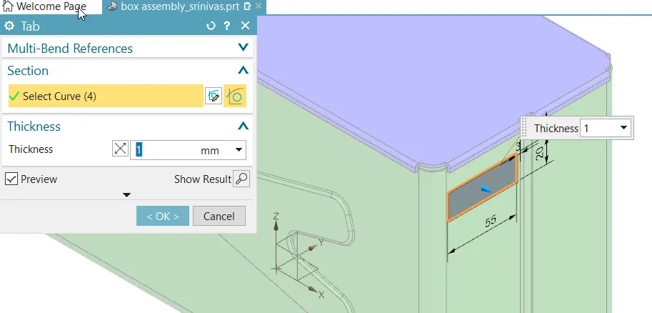
Figure 16: Creating a tab at right side for hinge support.
Tab is created at right side to support or to create a hinge.
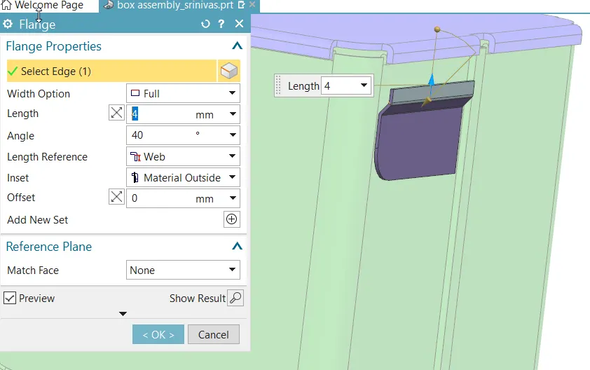
Figure 17: Creating a flange for hinge support
After creating a tab two flanges are created with same dimension values as shown in above figure.
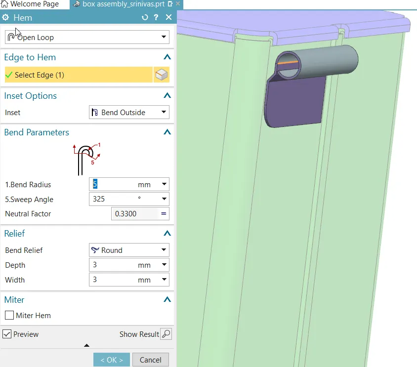
Figure 18: Creating a hem to make hinge
After flange hem is created with the dimensions bend radius 5mm and sweep angle 325mm.
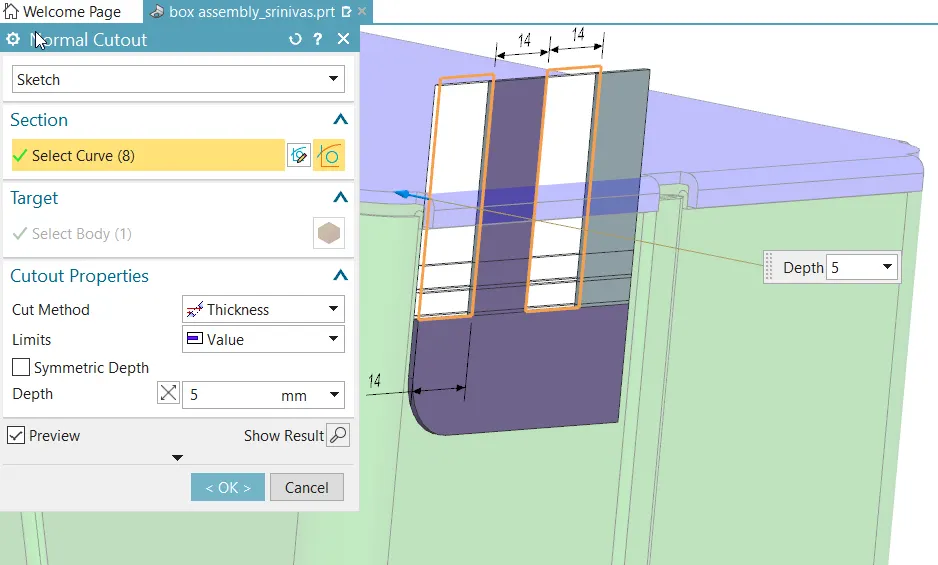
Figure 19: Creating a Normal cutout
After hem feature the part is unbend to make a normal cutout with 5mm depth as shown in figure.
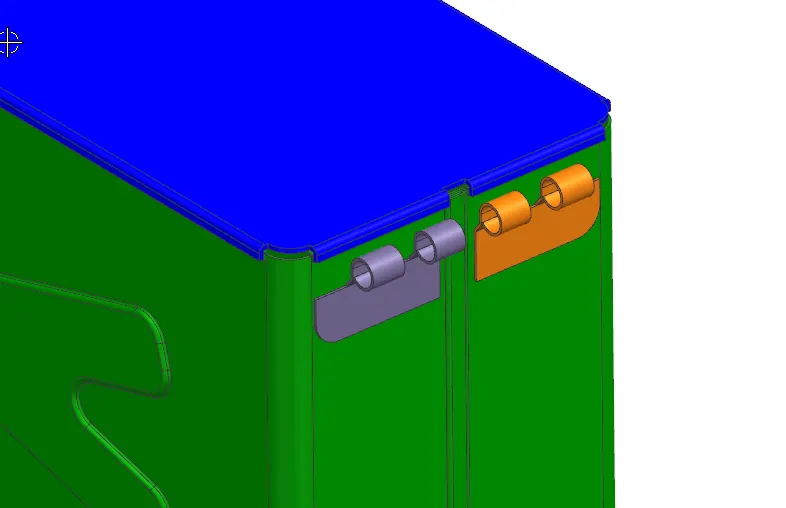
Figure 20: Mirror the bottom hinged part
After completing normal cutout, the part is rebend to its original position and then mirrored the part w.r.t to ZX plane.
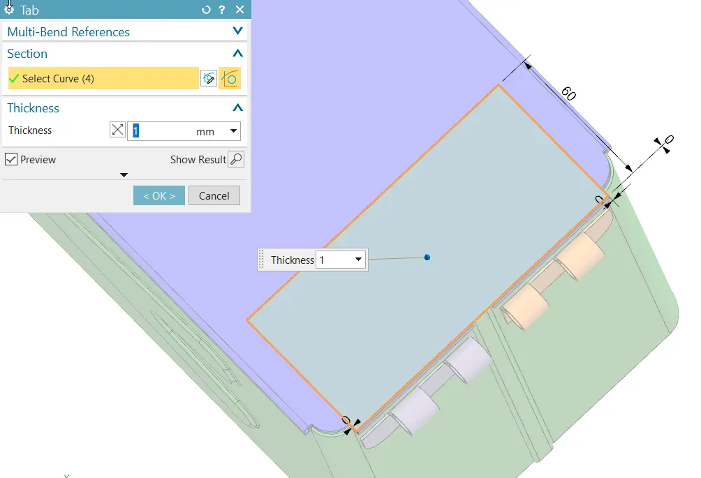
Figure 21: Creating a tab at top surface of the cover/cap
Tab is created to make hinge as a base part with thickness 1mm as shown above figure.
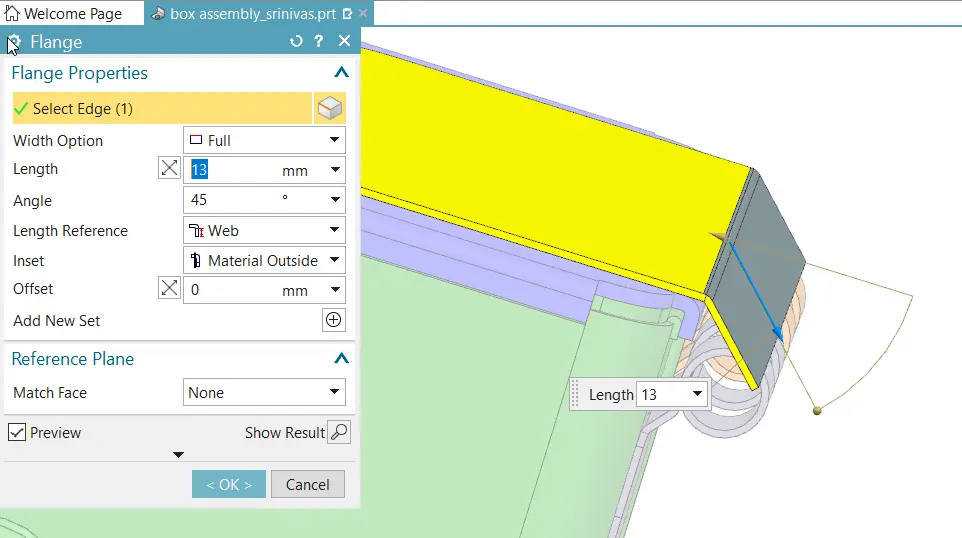
Figure 22: Creating a flange to tab for top hinge support
Here the flange is used to maintain angle 45 degree and length 13mm.
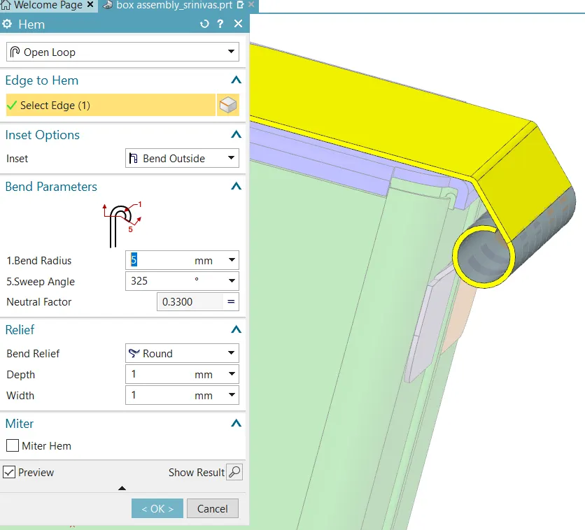
Figure 23: Creating a hem for top hinge support
Hem is created from selecting edge of the flange with bend radius 5mm, sweep angle 325mm as shown in above figure.
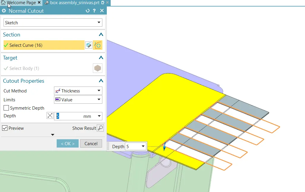
Figure 24: Creating a normal cutout of hem
Top hinge support is done unbend and used normal cutout (sketched w.r.t to bottom hinge).
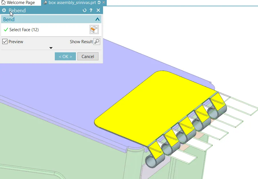
Figure 27: Creating a Rebend of top hinge part
After cutout the part is rebend to its original position.
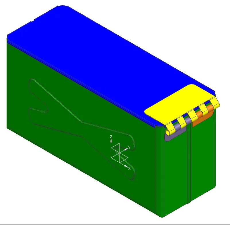
Figure 28: Isometric View
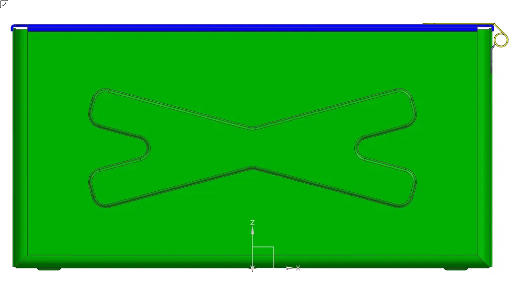
Figure 29: Front View
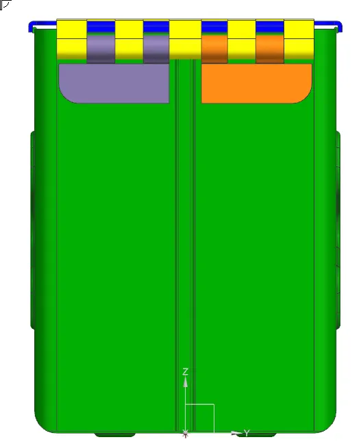
Figure 30: Side View
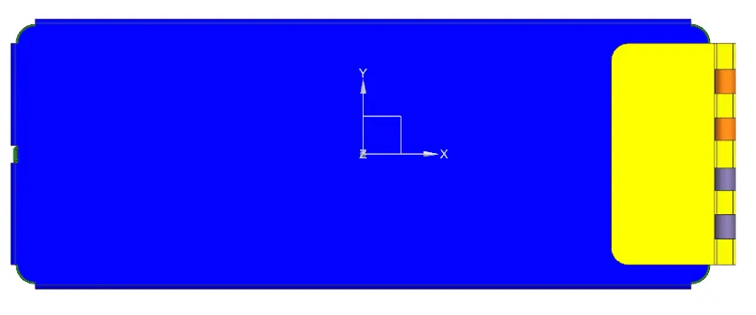
Figure 31: Top View
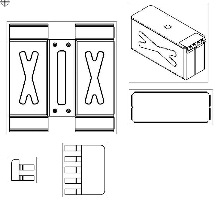
Figure 32: Detail drawing View
Conclusion:
I have understood the NX software tools (Tab, Normal Cutout, Flange, Break Corner, Bend, Dimple, Bead, mirror, Closed corner, Hem, Unite, Rebend, Unbend, Flat pattern and 2D detailed drawing) and developed a 3D model of sheet metal box assembly.