Advanced Sheet Metal Design Using NX Cad Challenge_6_Bracket
Developing a Sheet Metal Bracket using NX CAD
Objective
The aim of the work is to create a bracket by using NX sheet metal applications.
Introduction
In this project, creating a sheet metal bracket from 2d drawing using NX CAD and the features like bead, hole, contour flange, unbend and rebend are added.
Design Methodology / Approach
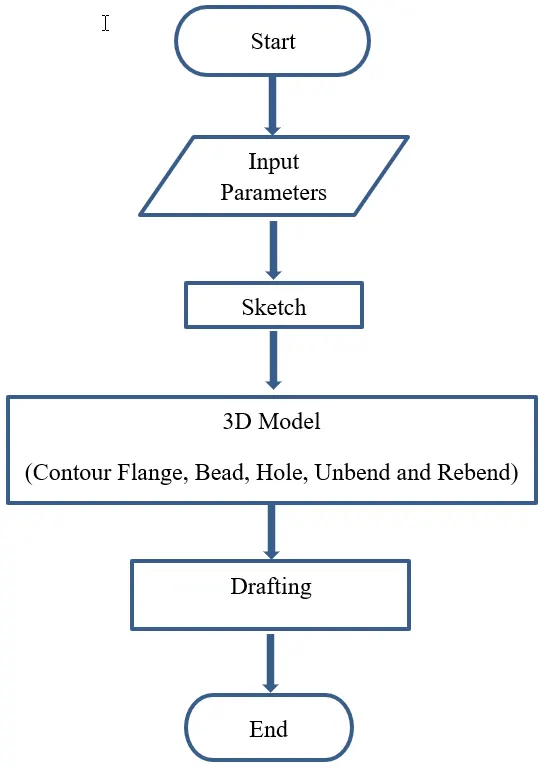
Figure 1: Flowchart of developing of sheet metal bracket
Description (Need to explain tools / Features used while designing)
Step by step procedure developing a sheet metal bracket.
Step 1: Creating a Contour flange.
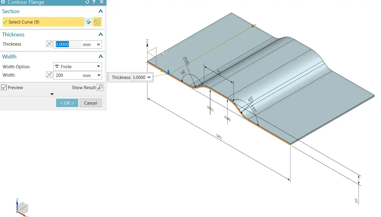
Figure 2: Contour flange
In ZX plane sketch is created and then contour flange feature is selected. Now select the curve and give the width 200 mm distance as shown in figure 2.
Step 2: Normal Cut-out
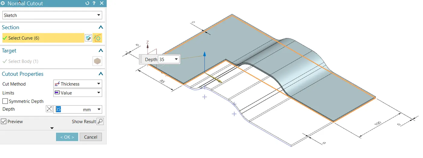
Figure 3: Creating a normal cut-out feature
After completion of contour flange select the top surface to draw a sketch entity and then use normal cut-out to remove the unwanted portion as shown in figure 3.
Step 3: Break corner at sharp edges
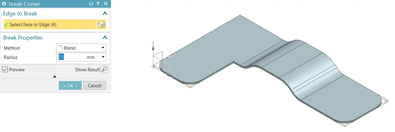
Figure 4: Break corner 25mm dia.
Select the edges and give the blend radius 25mm.
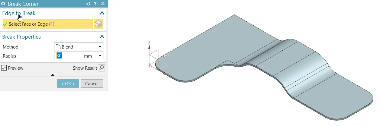
Figure 5: Break corner 30mm dia.
Select the edge and give the blend radius 30mm.
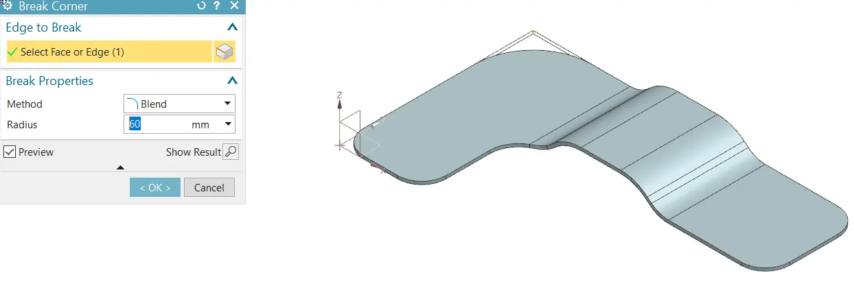
Figure 6: Break corner 60mm dia.
Select the edge and give the blend radius 60mm.
Step 4: Unbend
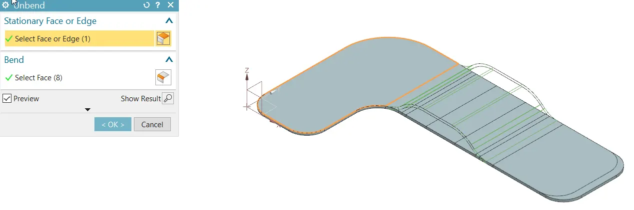
Figure 7: Unbend
Part is unbend to create a features on top surface.
Step 5: Bead
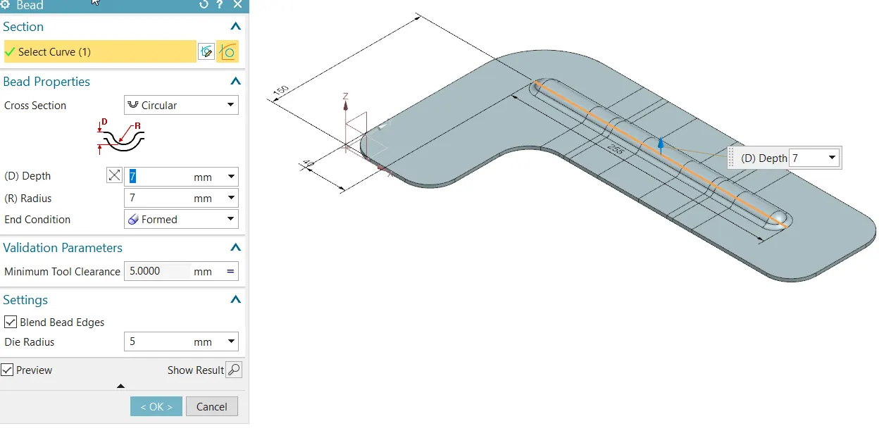
Figure 8: Creating a bead
Sketch is drawn on top of the surface and selected the sketch entity while using a bead feature. The parameters are shown in figure 8.
Step 6: Rebend
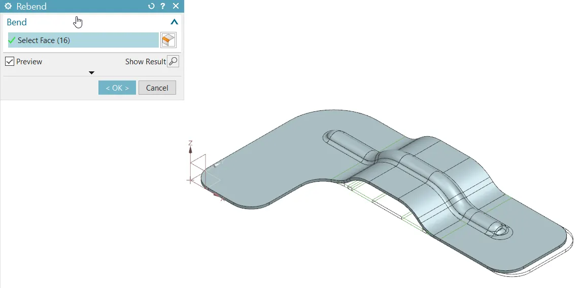
Figure 9: Rebend
Rebend to original position
Step 7: Hole
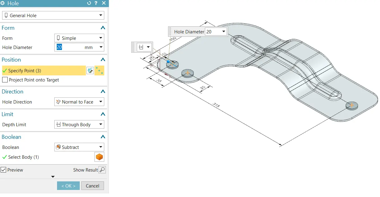
Figure 10: Creating a hole
First creating a point for holes then w.r.t to points the hole is created as shown in figure 10.
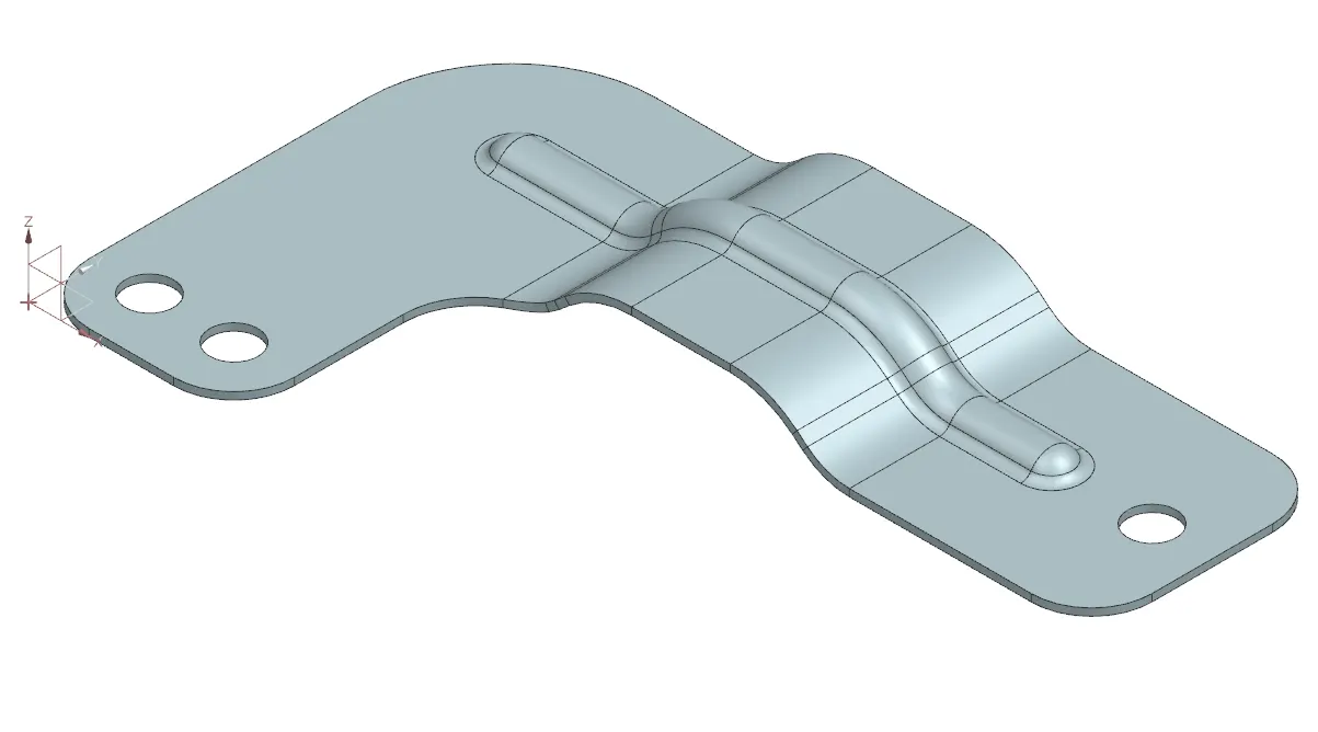
Figure 11: Isometric View
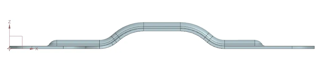
Figure 12: Front View
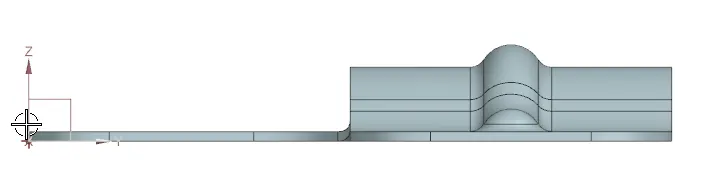
Figure 13: Side View
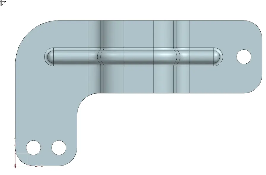
Figure 14: Top View
Step 9: Drafting
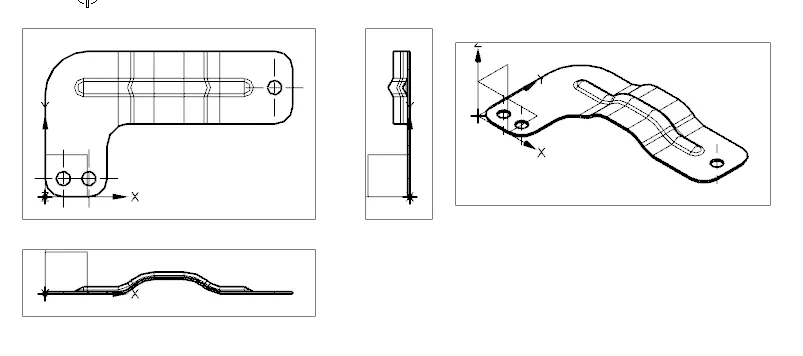
Figure 15: Drafting
Conclusion:
Developed / Created a bracket by using NX sheet metal applications.