Advanced Sheet Metal Design Using NX Cad Challenge_5_Odd Shaped Enclosure
Developing a Sheet Metal Odd Shaped Enclosure using NX CAD
Objective
The aim of the work is to create an odd shaped enclosure by using NX sheet metal applications.
Introduction
In this project, creating a sheet metal from solid part by using different features like sheet metal from solid, bead, flange, jog, hole and flat pattern. Flat patterns are useful at manufacturing point of view.
Design Methodology / Approach
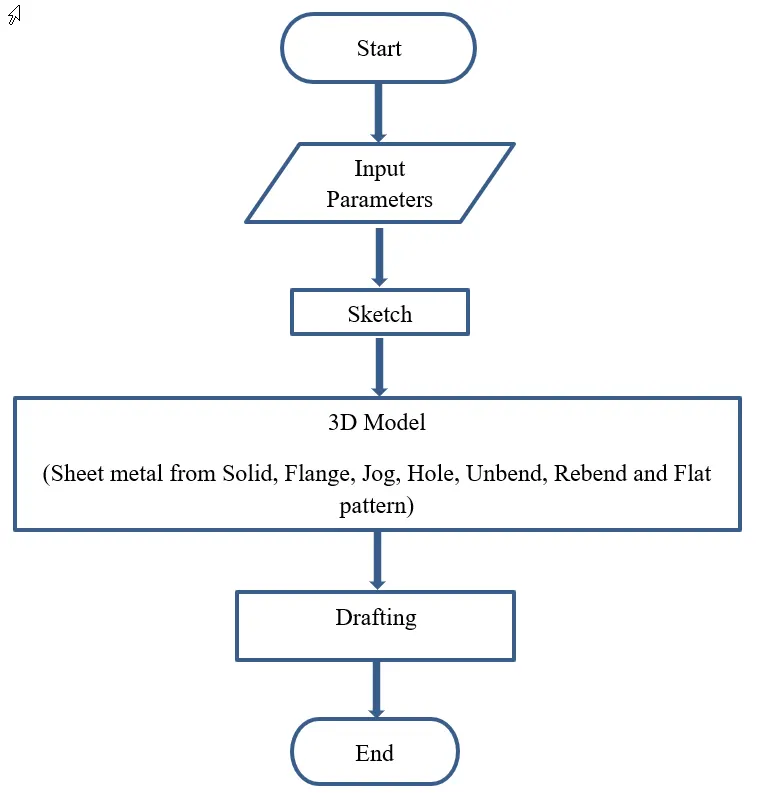
Figure 1: Flowchart of developing of sheet metal odd shaped enclosure
Description (Need to explain tools / Features used while designing)
Step by step procedure developing a sheet metal odd shaped enclosure.
Step 1: Creating a solid part by using extrude feature.
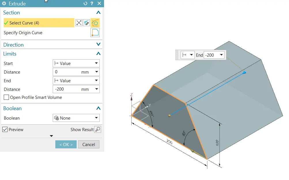
Figure 2: Extrude
In ZX plane sketch is created and then extruded 200 mm distance as shown in figure 2.
Step 2: Converting Sheet metal from solid
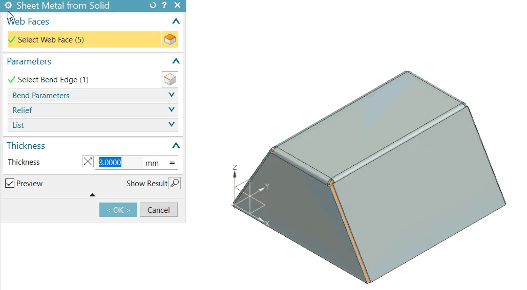
Figure 3: Sheet metal from solid
Extrude part has to convert into sheet metal for that purpose sheet metal from solid feature is selected and then select the faces which one needed (figure 3 the top 5 faces selected). Now the edges is to select to wrap the solid part and the thickness is used 3mm.
Step 3: Creating a flange
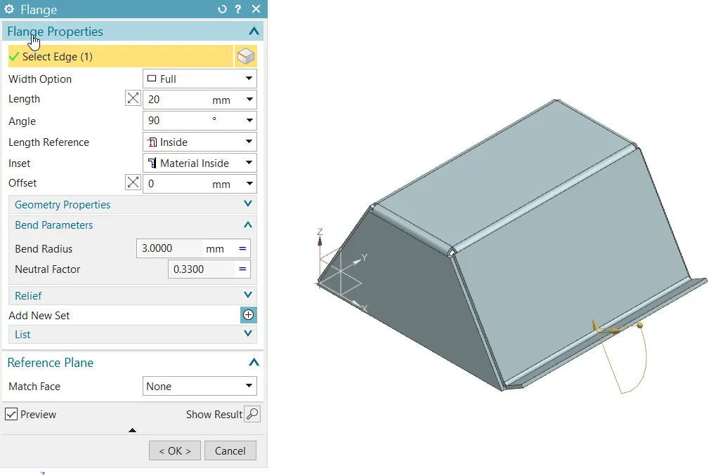
Figure 4: Flange
Select a one side edge to create a flange and the values as showed in figure 4.
Step 4: Creating a jog
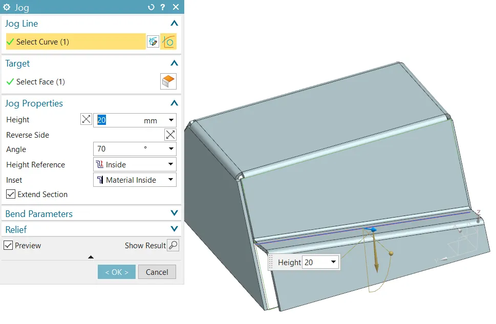
Figure 5: Jog
On another side created jog feature w.r.t to line entity. The line is drawn approximate in inclined. The jog parameters are shown in figure 5.
Step 5: Unbend
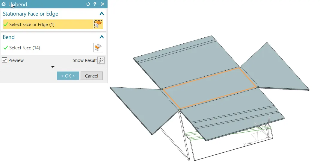
Figure 6: Unbend the sheet metal
The sheet metal is unbending to apply/create more features like bead and holes
Step 6: Creating a bead
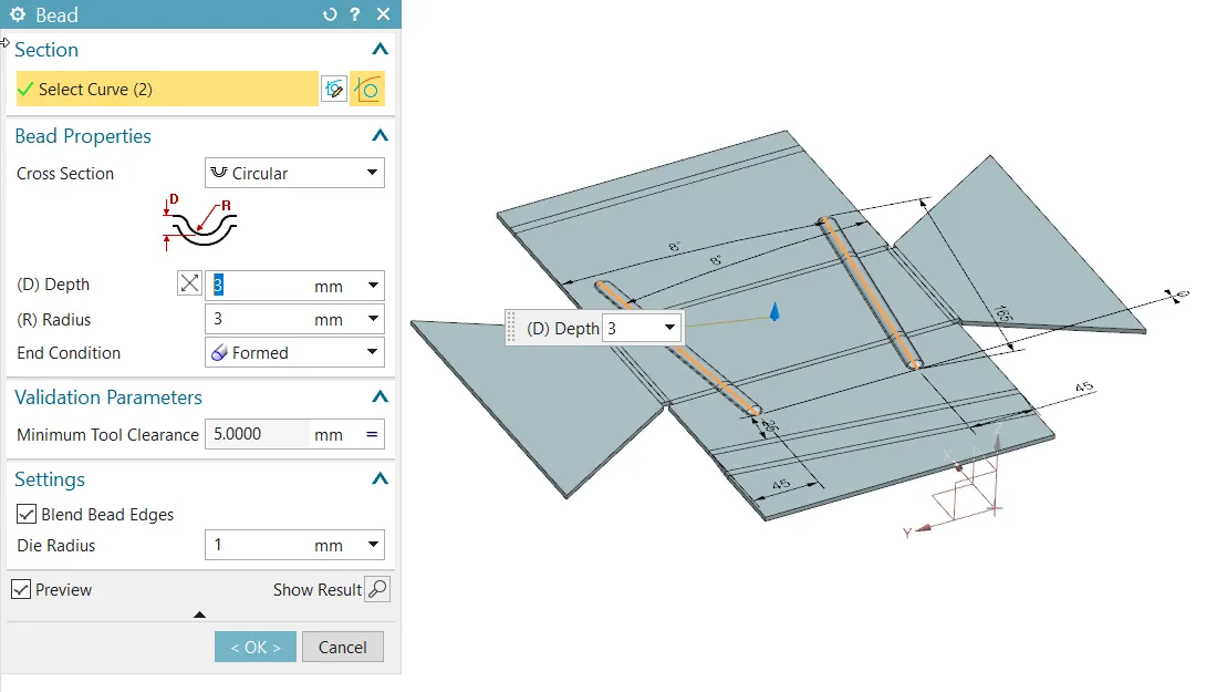
Figure 7: Bead
After unbending, the sketch is created roughly on the top surface then created a bead with the help of sketch entity as shown in figure 7.
Step 7: Creating a hole
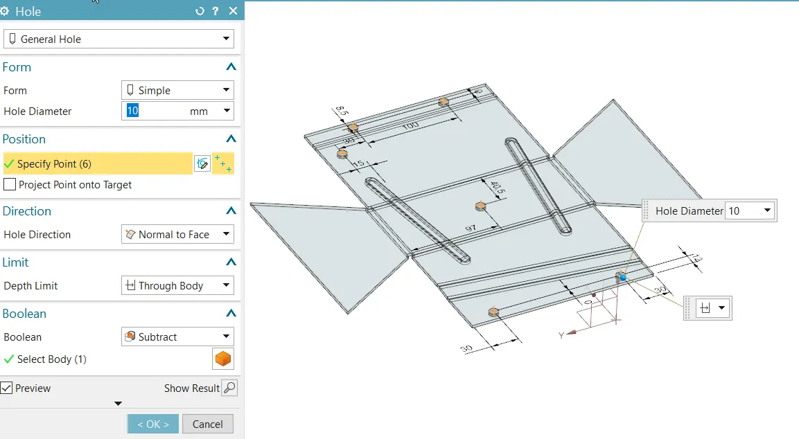
Figure 8: Holes
First creating a point for holes then w.r.t to points the hole is created as shown in figure 8.
Step 8: Rebend
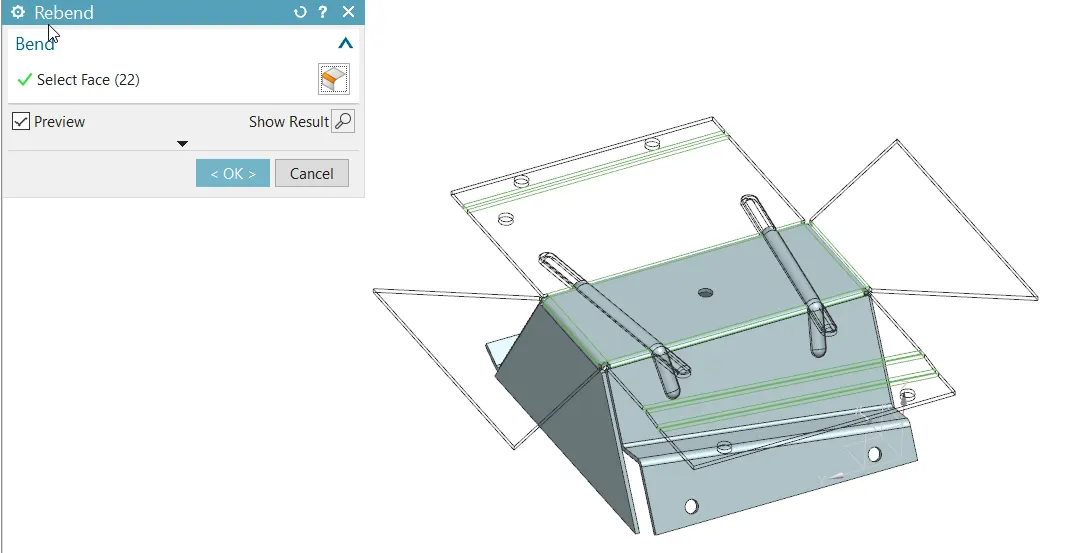
Figure 9: Rebend
After creating the features, the sheet metal part is bend to its original position.
Step 9: Creating a flat pattern
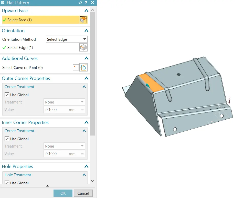
Figure 10(a): Flat pattern
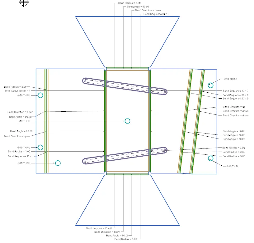
Figure 10(b): View of flat pattern
Figure 10(a) shows the step to create a flat pattern by selecting top face and edge to orient.
Figure 10(b) is the view of flat pattern and it is used for manufacturing purpose. It is easy to understand part for manufacturing.
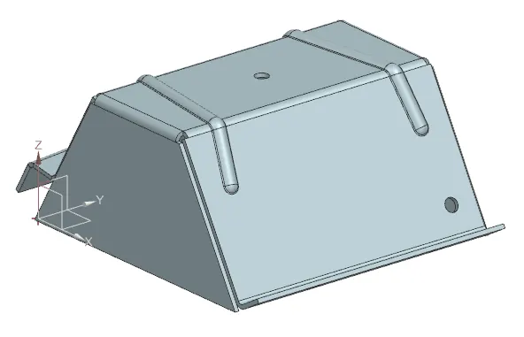
Figure 11: Isometric View
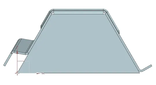
Figure 12: Front View
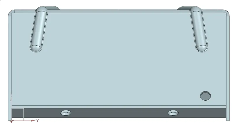
Figure 13: Side View
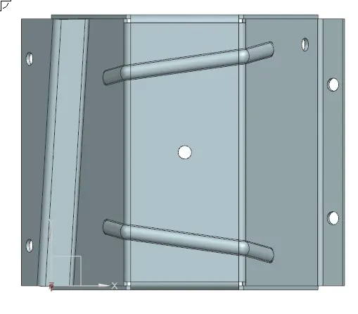
Figure 14: Top View
Step 10: Drafting
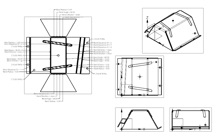
Figure 15: Drafting
Conclusion:
Developed / Created the odd shaped enclosure by using NX sheet metal applications.