Advanced Sheet Metal Design Using NX Cad Challenge_1_Casing Design
Title - Developing a sheet metal casing using Nx software
Objective
The aim of the work is to understand the NX software tools (Tab, Normal Cutout, Flange, Break Corner, Bend, Hole, Dimple, Bead, Flat pattern, mirror and 2D detailed drawing) and create or develop a 3D model of sheet metal Casing.
Introduction
Sheet metal is a metal forming processes into thin and flat pieces, the fundamentals of sheet metal is to cut and bend the sheets by using punch and die operations. The sheet metal thickness ranges from 0.5mm to 6mm. Many industries prefer sheet metal to reduce the cost, reduce the no. of operations, reduce the time, increase the efficiency of production and developed the part with minimum trial and errors in a short time.
Nx is also known as Unigraphics, it is flexible, powerful, innovative product developed solution and advanced high-end software in CAD / CAE / CAM.
Design Methodology / Approach
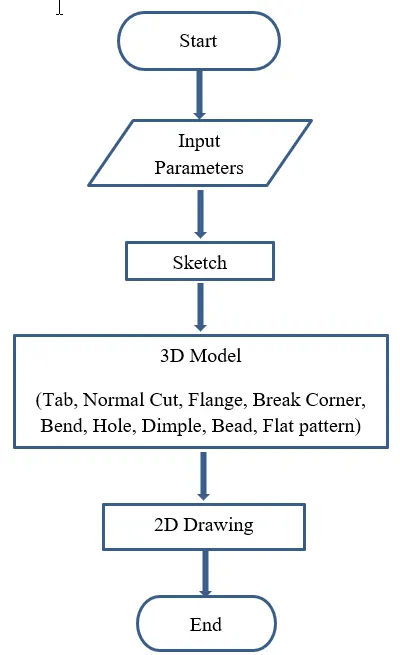
Figure 1: Flowchart of developing of sheet metal casing
Description (Need to explain tools / Features used while designing)
Tab: It is used to convert 2D sketch to 3D. Tab is also known as base part (extrude at certain thickness)
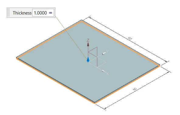
Figure 2: Creating tab feature
For creating a sketch selected XY plane, drawn a rectangle from center from the origin point with a dimension of 60mm (X direction) and 50mm (Y direction) and exit the sketch. Click on Tab feature and select the curve (sketch) and give the thickness value.
Normal Cutout: Normal Cutout is nothing but cutting the material perpendicular to the face along with continuous sketch entities.
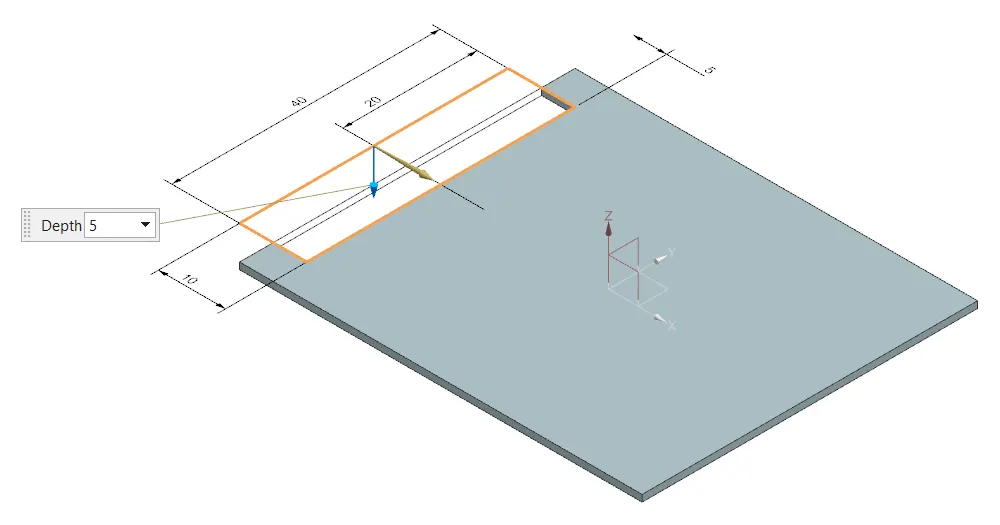
Figure 3: Creating normal cutout feature
To make a normal cutout at the top face of the base or tab is selected and drawn a rectangle sketch and the dimensions are used 5mm width from the base plate edge and 40mm long is maintained symmetric w.r.t to x-axis.
Bend: It allows to bend the material along with Sketch (line) entity.
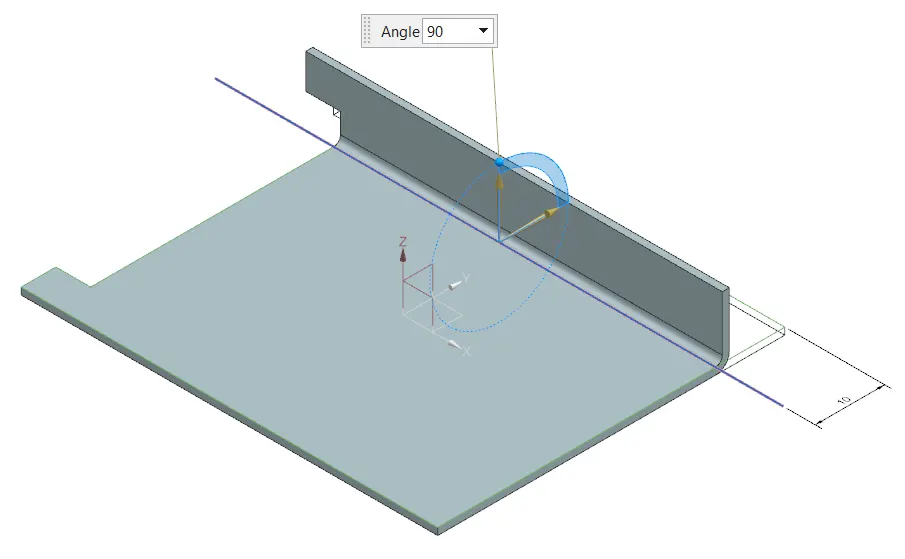
Figure 4: Creating bend feature
Drawn a line on top face of base feature, maintained the dimension 10mm from line to edge of the base feature and maintained bend angle 90 degrees. Again, same procedure is done at another end by creating line and bending the base feature along the line entity.
Flange: Flanges are nothing but joining the two parts with the help of welding or rivets.
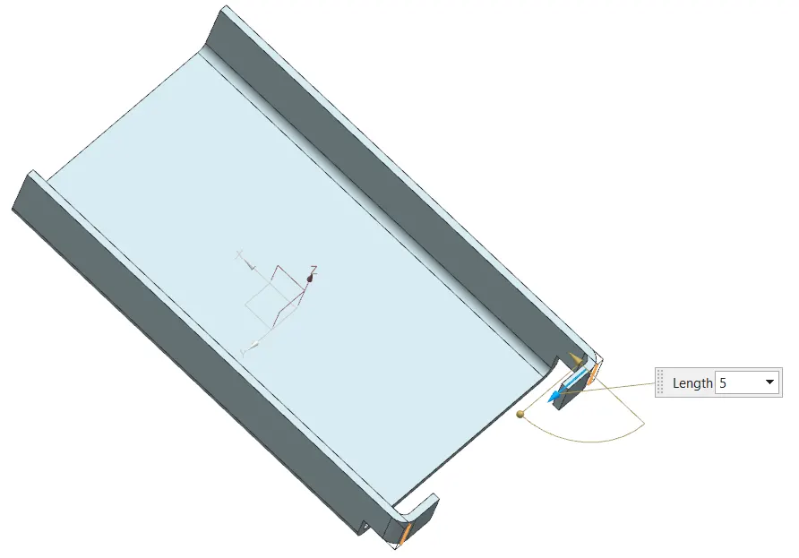
Figure 5: Creating flange feature
The flange feature is selected at edges and without using any bend relief. Length, radius and angle of the bend is 5 mm, 1 mm and 90 degrees.
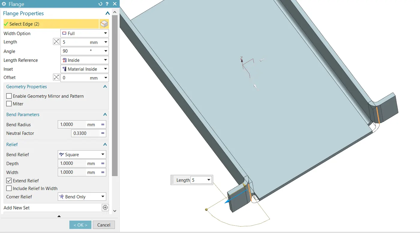
Figure 6: Creating flange feature with bend relief
Similarly, the bend radius 1mm, length 5mm and 90-degree angle. Here the bend relief is used and its type is square relief. The dimension for relief is used 1mm for depth and width.
Break Corner: It consist of two method blend (radius) and chamfer (distance and angle). Break Corners are used to avoid sharp edges and damages are reduced while assembling the parts.
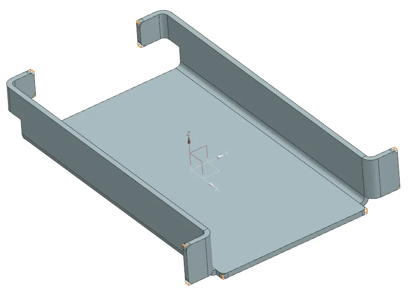
Figure 7: Creating break corner feature
Selecting break corner feature and selecting all sharp edges. Use the method as blend and maintain the radius is 1mm.
Unbend: Creating a complex shape within bended sheet metal the tool moment is very difficult. For that purpose, the bend sheet metals are flattened by using unbend feature.
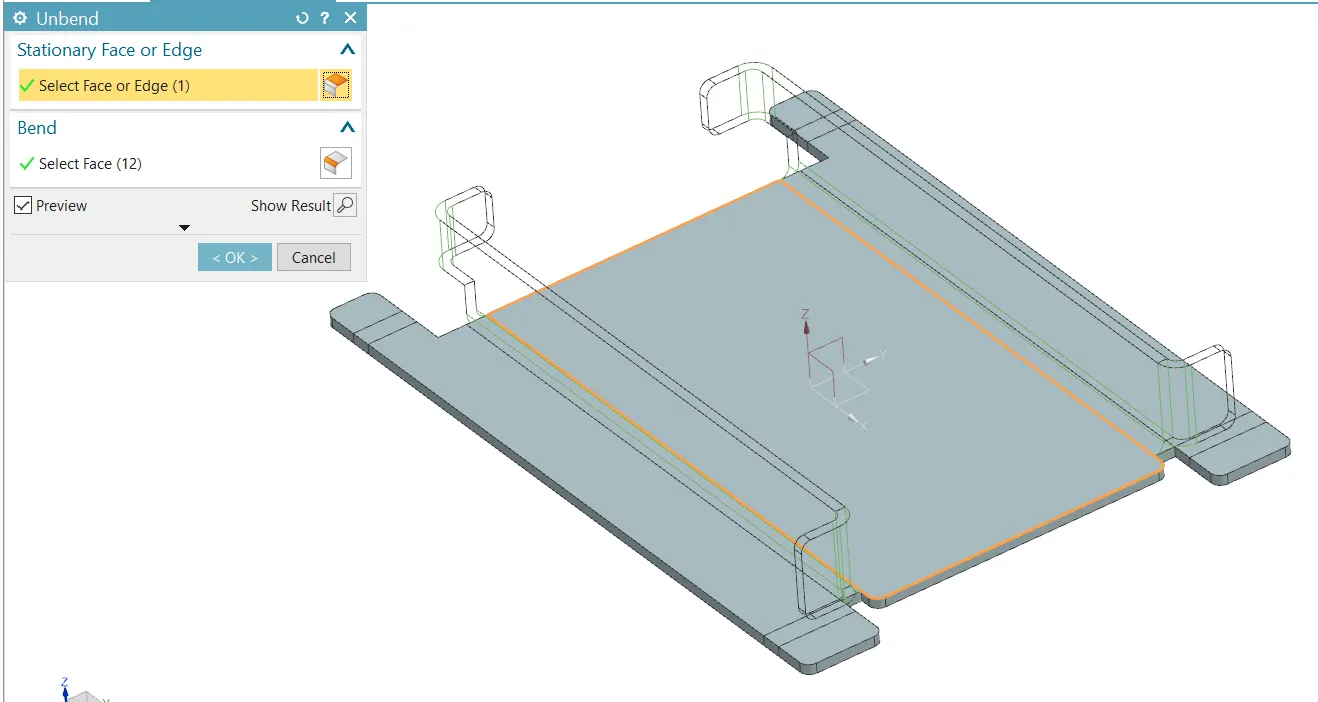
Figure 8: Creating unbend feature
Selecting the face which wants to make a constant/fix and remaining bend features are unbend w.r.t to constant face.
Hole: Holes are used to join the different parts to make product by using rivets.
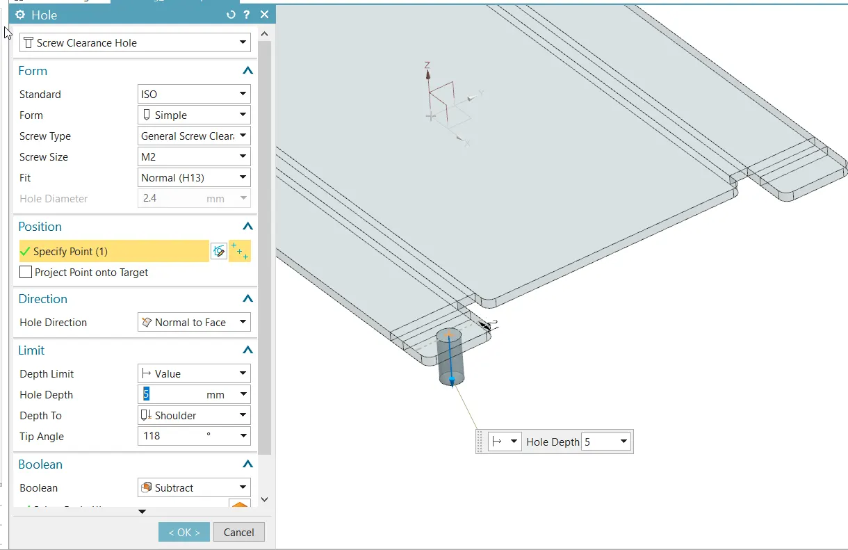
Figure 9: Creating hole feature
Click on hole feature, click on sketch option, now draw a line at top surface near to edge and convert it construction line. Now create a point w.r.t to construction line center point and exit the sketch. Give the screw size value M2 and depth through hole or 5mm then click okay. Similarly, create hole feature all the sides.
Mirror Feature: Mirror feature is a tool to copy the feature and mirror it across the plane.
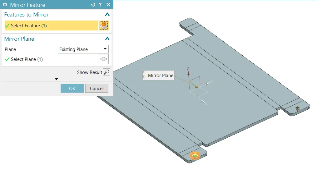
Figure 10: Creating mirror feature
Mirroring the hole feature along the ZX plane.
Similar way another side create a hole and mirror the hole feature.
Dimple: Dimple is used to lift the material within closed sketch entities.
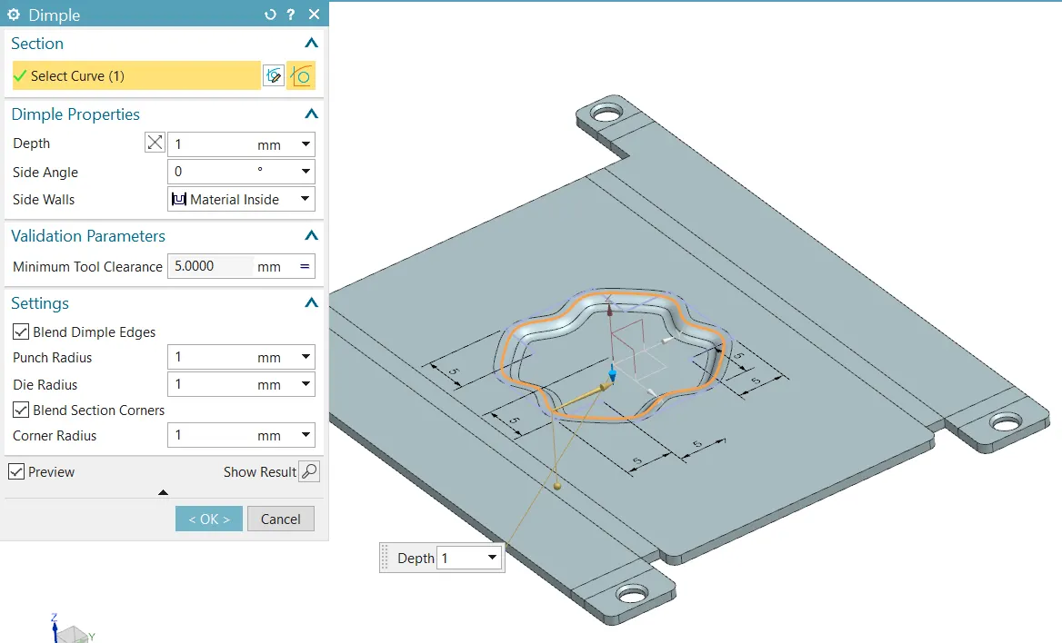
Figure 11: Creating dimple feature
Click on dimple feature and select top surface and sketch the profile with maintaining 5mm length with origin or centered at (0,0,0). Now select the spline (studio spline) and the sketch is drawn at an angle of 45degrees then exit the sketch. In dimple feature the value 1mm is used for all (depth, punch radius, die radius and corner radius) then click okay.
Bead: Bead is also used to lift the material along the contour of a sketch.
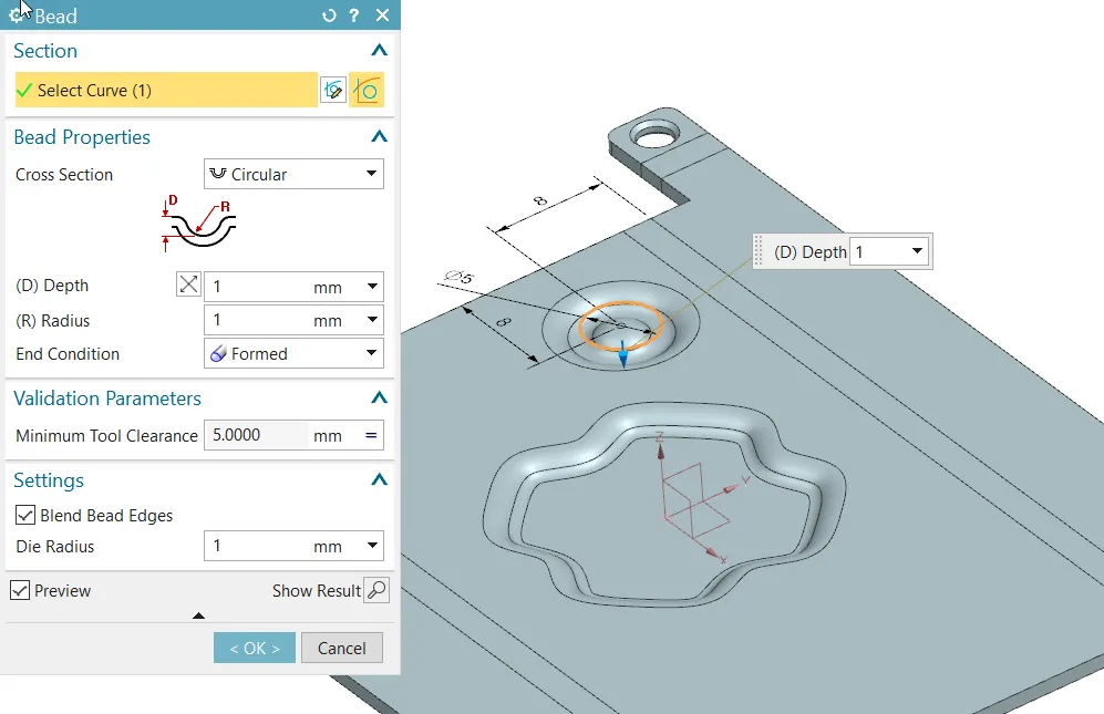
Figure 12: Creating bead feature
Creating a circular sketch on top face at one edge, diameter 5mm, 8mm at edges shown in pic. Give the values 1mm for depth, radius, blend bead edges then click okay. Similarly mirror the bead feature at four sides.
Sheet metal casing views:
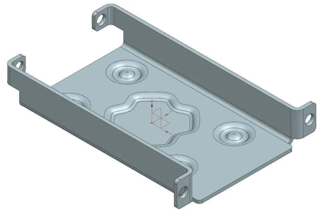
Figure 13: Isometric View
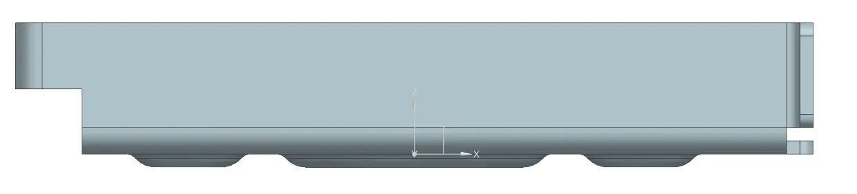
Figure 14: Front View
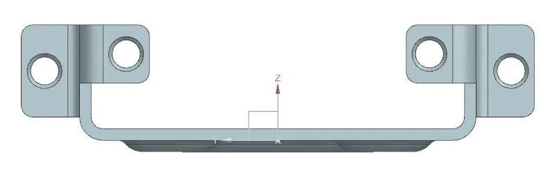
Figure 15: Side View
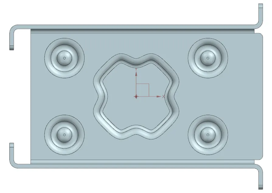
Figure 16: Top View
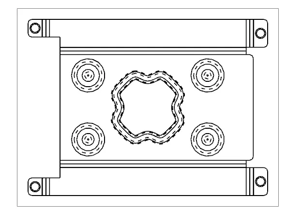
Figure 17: Detail drawing View
Conclusion:
I have understood the NX software tools (Tab, Normal Cutout, Flange, Break Corner, Bend, Hole, Dimple, Bead, Flat pattern, mirror and 2D detailed drawing) and developed a 3D model of sheet metal Casing.