Fender Design Challenge
Title: Design and Develop a Fender from Class A Styling Surface
Objective:
The aim of these project is to design fender and the main design requirements for Drip, Bumper, A pillar and Sill mounting areas.
Introduction:
Fender
Fender is a front outer side member of a car which covers the wheel side. Fender purpose is to prevent sand, mud, rocks, liquids and other particles. or
Fender is a closure component, closing the engine compartment and other compartments. The major role of the fender is to avoid the chipping inside the engine compartment. During the motion the wheel picks a sand mud and small stone particles and throws it inside the car and these fenders will be helpful in preventing them by hitting inside the engine compartment and car body. These fenders will have a plastic part which lies on wheel arch area. The fender plays a major role to avoid problems for pedestrian also.
Types of Fenders
- Full bumper types
- Half bumper types
Full bumper types are used in past. It has a large blank size and a lot of wastage while creating shapes etc.
Half bumper types are used in present and future also because the blank size is less and the wastage or scrap is less comparing to full bumper type fenders.
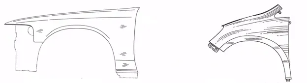
Figure 1: Full and Half bumper fenders
Important areas to be considered while designing a fender:
- Drip area
- Bumper mounting area
- Sill mounting area
- Body mounting area
The drip area is the connection of the fender with the engine compartment.
The bumper, sill and body mountings are design with the help of bumper, sill and body portion.
Input parameter to design a mounting in fender:
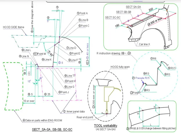
Figure 2: Input parameters for develop a drip area
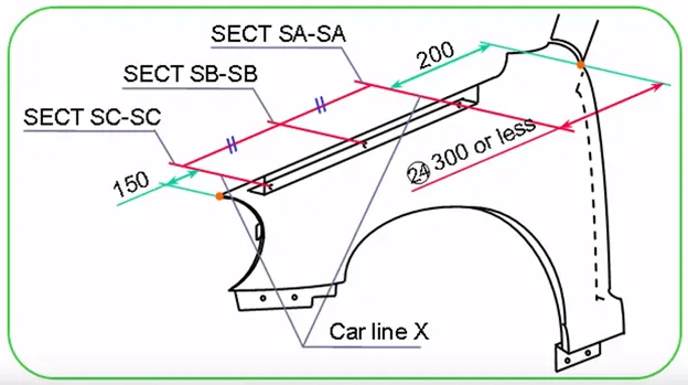
Figure 3: Spacing for Drip area from Cowl and Head lamp unit area.
The gap from rear fender of the fender and front fender of the fender
The cowl part is carrying the wiper motor and its instruments to have sufficient mount space for the cowl will have minimum 200mm.
The head lamp is having housing unit to sufficiently place for these required minimum space 150mm.
The drip mounting length varies from different cars.
Drip depth shall be uniform A=B=C.
If depth unavoidably varies, it shall be either A>B>C or A<B<C.
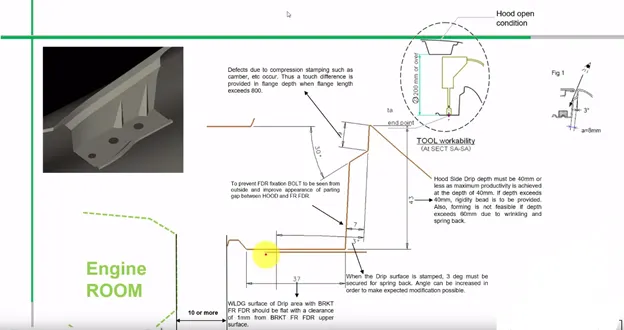
Figure 4: Developing drip area and importance of dimension values
The above figure shows the importance dimensions to be maintained and every dimension are explained in figure itself.
- The depth of drip should not be exceeding 60mm, if it is exceeds then the forming is not feasible due to wrinkling and spring back effect
- 3-degree, 30 degree and 8mm or 7mm distance are used not to visible inside components like engine component and fasteners etc.
- 37mm is used to join with another part or bracket and the clearance of 1mm from breaket front fender and drip surface.
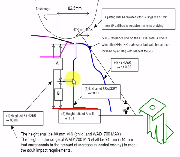
Figure 5: The dimensions for height of the fender.
The above figure shows the height range of the fender based on child and adult to meet the impact requirements.
- The parting line should be within a range of 47.5mm, if it is exceeding 47.5mm then there is problem in terms of styling surface.
- The thickness fender is t=0.65 but in this project used 0.75mm thick.
- The L-shaped bracket thickness is 1mm. The height ratio of A and B are 1:1 i.e., is 40+40=80mm.
Procedure
Step 1:
Drip area Creating with the help of inputs from figures 2, 3, 4 and 5.
The features are used to create are Law extension, Emboss, Trim sheet, Edge Blend, Face Blend, Skew and Dart.
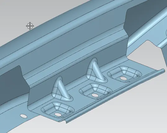
Figure 6: Drip area mounting
Design Consideration for drip area are
- 150mm distance from front end of the fender and the gap is filled with headlamp.
- 200mm distance from rear end of the fender and the gap is filled with wiper motor assembly.
- Initially 3-degree angle and 9mm length is given while creating a drip area because the engine component should not be visible from outside.
- The depth of the drift should be between 40 to 60mm. If the depth exceeds from 60mm then forming is not feasible due to spring back and wrinkles.
- Embosses and ribs are given to drip area to give strength. Embosses dimensions are depth 3.5mm and 15 degree of angle for all three embosses. Dart dimensions are angle 45-degree, depth 8mm and 3.75mm. For dart and embosses the blend radius is 3mm used.
Step 2:
Bumper Mountings are taken randomly, in real time bumper mounting are design with the help of bumper.
The features are used to create are Law extension, Emboss, Trim sheet, Edge Blend, Skew and Dart.
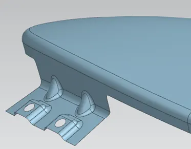
Figure 7: Bumper mounting
- Law extension length 20mm and 75 degree of angle.
- Skew to join the two surfaces.
- Dart angle 45 degrees, depth 4mm and radius 3.75mm. Create two darts in existing spaces as shown in figure 7.
- Trim sheet is used to create a hole of dia 5mm.
- For skew use 3mm edge blend and for dart and embosses 2mm edge blend.
Step 3:
Sill mountings are created randomly and in real time the mounting and given from sill body portion.
The features are used to create are Extend sheet, Emboss, Trim sheet, Edge Blend.
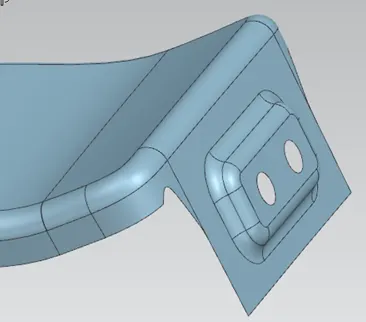
Figure 8: Sill mounting
- Extend sheet to 15mm to make the sheet length 30mm.
- Giving relief by manual like creating a sketch and trim the sheet both sides.
- Emboss dimensions are depth 3.5mm and 15 degree of angle.
- Edge blend is 3mm.
- Trim sheet is used to create a 5mm hole on sheet.
Step 4:
A pillar mounting is created with the help of A pillar structure.
The features are used to create are Law extension, Offset and Edge blend.
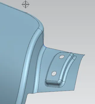
Figure 9: A pillar mounting
- Law extension dimensions are 42mm length and 90 degree of angle.
- Offsetting the law extension face 5mm.
- Creating a sketch and law extension feature is used 6mm length and 95 degree of angle.
- Trim sheet to create a hole of 5mm diameter.
- Edge blend and face blend are 2mm.
Step 5:
Creating holes for baffles.
Trim sheet feature is used to create holes of 5mm.
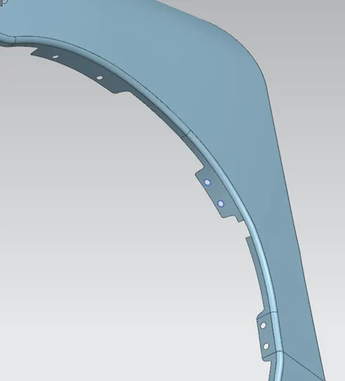
Figure 10: Baffle position.
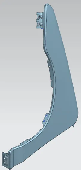
Figure 11: Isometric View
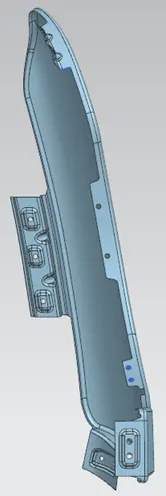
Figure 12: Front View
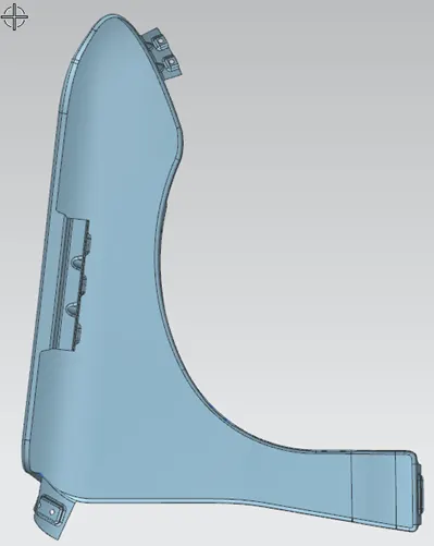
Figure 13: Side View
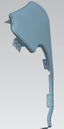
Figure 14: Top View
Conclusion:
Developed the Drip, Bumper, Sill, A pillar and Baffle mounting areas by design requirements of the fender design.
https://drive.google.com/drive/folders/1vhvJVvvtdnp_pHw2Wj1H5iL_bhZaAAlo