Roof challenge
Title: Design and Development of Roof Design
Objective
Developing a roof design based on the styling surface and from the master sections. The bow roof1, bow roof2 and center roof rail was developed from the given input master section. Roof design is studied with heat distortion criteria and snow criteria conditions.
Introduction
The roof is a important part of the car which protects the passenger from different conditions like heat distortion, snowed and any accidents etc.
Roof is not a single panel which has reinforcement inside like front roof rail, bow roof1, center roof rail, bow roof2 and rear roof rail. The bow roof is positioned on flat surface area of the car. Depends upon car length the bow roofs will be added for example a van has 3-4 bow roofs. Rear roof rail is joined with back door and front roof rail is joined with shield glass and body side.
Front roof rail
Front roof rail is an additional commodity which is been given as a reinforcement.
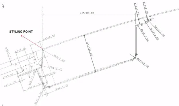
Figure 1: Master section of front roof rail
Styling point is nothing but the point at edge of the styling surface as shown in above figure.
Due to deep drawing situation the face is opened at 3 degree, if the 3 degree changes to 5 degree then the flange 21.5mm is move inside means the visibility criteria of the wind shield glass is not satisfied. The front roof rail the flange is maintained 21.5mm. Wind shield glass thickness varies from 3.7mm to 4.7mm. Below the wind shield glass rubber is pasted and the paste thickness is 4 to 5mm and they’re also a sealant which is running throughout and these sealants will have to considered as thickness. Considering all these points and prepared surface offset of wind shield glass and roof surface to particular value, which will contribute as to get a point and the length. Wind shield and rubber dimensions which will be contribute to 21.5mm. 32mm offset has reason and it depends upon the visibility criteria and minimum 80mm is followed because for front driver seating should be maintain minimum clearance.
Rear Roof Rail
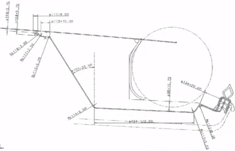
Figure 2: Master section for rear roof rail
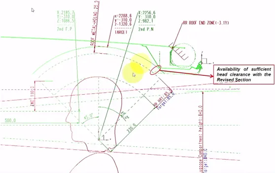
Figure 3: Head clearance from roof and rear roof rail
Approach:
- Removal of surface and maintain surface similar to roof side rail.
- Increase strength
- Smooth rear roof area connection with PLR, RR, INR.
- Effective material usage.
Similarly, the rear roof rail under these situations again we have conditions of the rear head room clearance and the rear visibility criteria.
Center roof rail, Bow roof1 and Bow roof2
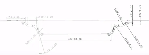
Figure 4: Master section for center roof rail
Approach:
- Addition of mastic, bead area in reinforcement roof CTR (increase strength)
- Since mastic bead added, possibility to reduce bow roof 1
- Thickness reduced from base (2.3 to 1.5 mm) for mass reduction
- Usage of high tensile material to increase strength.
These are depending upon again head room clearance and the deepness based upon the headlines.
Roof Mastic Information
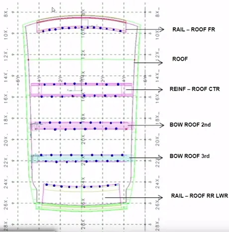
Figure 5: Roof mastic points information
Mastic points available between the roof reinforcement and outer panel. Whenever the mastic is adding there is a remarkable region of strength improvement. Spot welds also introduced for joining the panels towards to complete the assembly.
Roof Crush Test
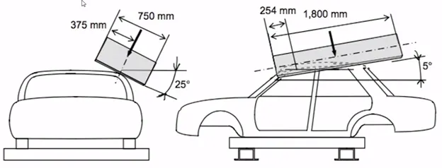
Figure 6: Crush test
Mainly for roof test use rollover test but present used roof crash test.
- Initially the condition of the test sample is to close and lock all the doors & close the windows.
- Fixing test sample is to fix the body sill or chassis frame on a hard level surface horizontally.
|
Crush Speed |
13mm / sec or less |
|
|
Load and displacement amount specifications. |
The displacement of the load application device is 127mm or less, when a load is 1.5 times and the unload weight is (N conversion value) for 22, 240N, whichever is smaller is applied. |
The displacement of the load application device is 127mm or less, when a load is 1.5 times and the unload weight is (N conversion value) is applied. (FMVSS No. 216 only) The requirements shown on the left are applied to GS40 (GS39) and SASO, irrespective of models. |
|
Time to test completion. |
Within 120 sec |
|
Assembly of Roof Design
According to the master sections the roof, front roof rail and rear roof rail is developed from the styling surface. Bow roof1, center roof rail and bow roof2 are developed from the roof surface, these three bow rails give strength to the roof. Each component the emboss is given for strengthen and mastic points are used to join with roof.
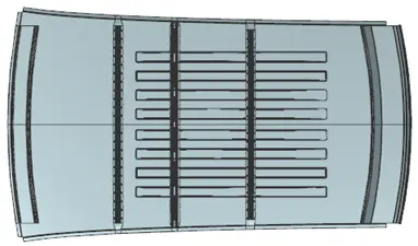
Figure 7: Assembly of roof design
Draft Analysis for each component
Draft analysis mainly enables to detect if the part drafted will be easily removed. The draft angle 7 degree is used with respect to y axis.
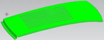
Figure 8: Roof outer part
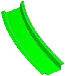
Figure 9: Front roof rail
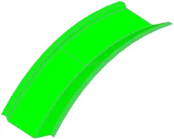
Figure 10: Rear roof rail
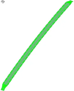
Figure 11: Bow roof1
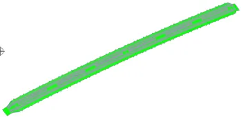
Figure 12: Center roof rail
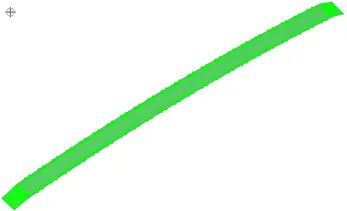
Figure 13: Bow roof2
Calculations:
Heat Distortion Criteria
The roof is exposed to heat for long time and the high temperature will effect the roof structure and the roof structure is satisfying or not is studied by heat distortion criteria.
Prediction formula:
W= 1.73 x 10^-3 x L + 1.85 x 10^-8 x (R^2)/2 + 1.10 x 10^-3 x l -268
Where,
L = Roof length in X-direction
R = Roof Curvature
R = 2(Rx x Ry) / (Rx + Ry)
Rx = X curvature
Ry = Y curvature
t = Roof plate thickness
l = Bow roof span
Judgement condition: ok < 2.7mm < NG
|
Heat Distortion Criteria |
||||||||||
|
S.No. |
Component |
Rx | Ry |
R |
l |
L |
t |
R^2/2 |
W |
OK/NG |
|
1 |
FRR-BR1 |
5789.1 |
2625.9 |
3613.0 |
435.9 |
2123.8 |
0.75 |
17,405,025.3 |
1.796 |
OK |
|
2 |
BR1-CRR |
5064.3 |
5800.2 |
5407.4 |
250.8 |
2123.8 |
0.75 |
38,986,633.0 |
1.99 |
OK |
|
3 |
CRR-BR2 |
4364.9 |
8734.5 |
5820.9 |
349.9 |
2123.8 |
0.75 |
45,177,169.1 |
2.2 |
OK |
|
4 |
BR2-RRR |
3424.1 |
13663.7 |
5475.9 |
610.8 |
2123.8 |
0.75 |
39,980,641.1 |
2.4 |
OK |
Snowed Criteria
The roof should be with stand environmental loads especially snow. If the roof is not able to with stand load then there will be a deformation on the roof. The snowed criteria study determines whether the roof is with stand or not.
Prediction formula:
Qr = (Iy x t^2) / a x s x ((Rx + Ry)/2)^2 x 10^-8
Where,
a = My x Lx^2 x 10^-2
My = Y(Ly - Y)
t = Roof thickness plate
Ly = Distance between the front and rear roof rail on vehicle OY (Ly is same for all component)
Lx = Distance between the left and right end of the roof on the roof bow
Y = Distance from FRR to BR
s = Distance for which bow roof bears divided load
s = L1 / 2 + L2 / 2
Iy = Moment of inertia
Rx = X curvature
Ry = Y curvature
Judgement Condition: Qr > 3.1 and 250 < s < 380
Moment of Inertia
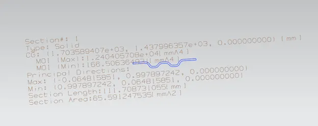
Figure 14: Bow roof 1
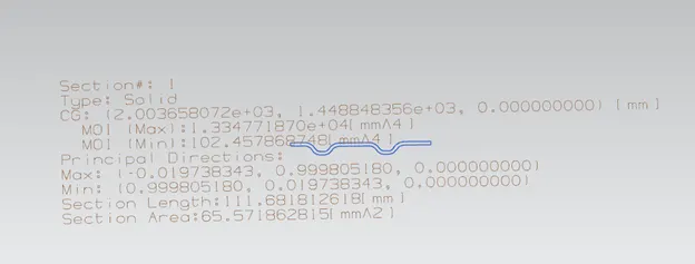
Figure 15: Center roof rail
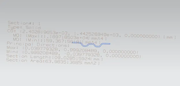
Figure 16: Bow roof 2
|
Snowed Criteria |
||||||||||||||
|
S.No. |
Component |
Iy |
α |
Lx | Ly |
Y |
s |
Rx | Ry |
t |
L1 | L2 | Qr |
OK/NG |
|
1 |
FRR-BR1 |
166.51 |
1.02 |
1137.88 |
2031.84 |
519.05 |
409.65 |
4490.51 |
2682.67 |
0.75 |
519.05 |
300.26 |
4.46 |
OK |
|
2 |
BR1-CRR |
102.46 |
0.62 |
1092.69 |
2031.84 |
300.26 |
349.59 |
3754.43 |
5705.4 |
0.75 |
300.26 |
398.93 |
3.04 |
NG |
|
3 |
CRR-BR2 |
159.37 |
0.75 |
1070.06 |
2031.84 |
398.93 |
567.88 |
4048.11 |
8891.7 |
0.75 |
398.93 |
736.83 |
1.29 |
NG |
|
4 |
BR2-RRR |
1.05 |
1048.71 |
2031.84 |
736.83 |
368.41 |
4196.26 |
15118.95 |
0.75 |
736.83 |
||||
Conclusion
- From the study of heat distortion criteria, the value of W is less than 2.5. So that, the heat distortion criteria are satisfied.
- From the study of snowed criteria the Qr value is less than 3.1 for bow roof2 and center roof rail and it is not satisfying for these reasons the emboss is given on roof to make strengthen and to satisfy the snowed criteria.