Advanced Sheet Metal Design Using NX Cad Challenge_7_ Metal bracket-II
Developing a Metal Bracket using NX Sheet Metal Application
Objective
The aim of the work is to create a metal bracket by using NX sheet metal applications.
Introduction
In this project, creating a sheet metal bracket from 2d drawing using NX CAD and the features like normal cutout, hole, contour flange, advanced flange and gussets are added.
Design Methodology / Approach
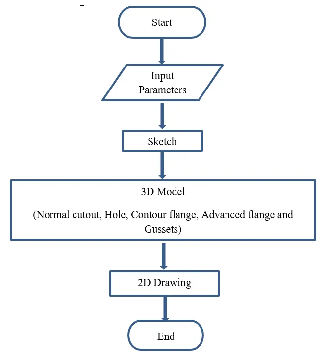
Figure 1: Flowchart of developing of sheet metal bracket
Description (Need to explain tools / Features used while designing)
Steps/Features involved in developing a sheet metal bracket.
- Contour flange creates a base feature.
- Normal cut out are used to remove material.
- Break corner are used to avoid sharp edges.
- Advanced flange is used to add a flange along the edge (Continues or tangency).
- Holes are used to make a standard counter bore, countersunk and thread.
- Gussets are used to give strength and stiffness to flanges/ bending.
- Unbend is nothing but making the sheet flat from bend position
- Rebend is the feature to make original position with bends.
Below figures will show the step by step procedure to make a metal bracket
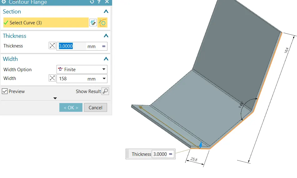
Figure 2: Contour flange
In ZX plane sketch is created and then contour flange feature is selected. Now select the curve and give the width 158 mm distance as shown in figure 2.
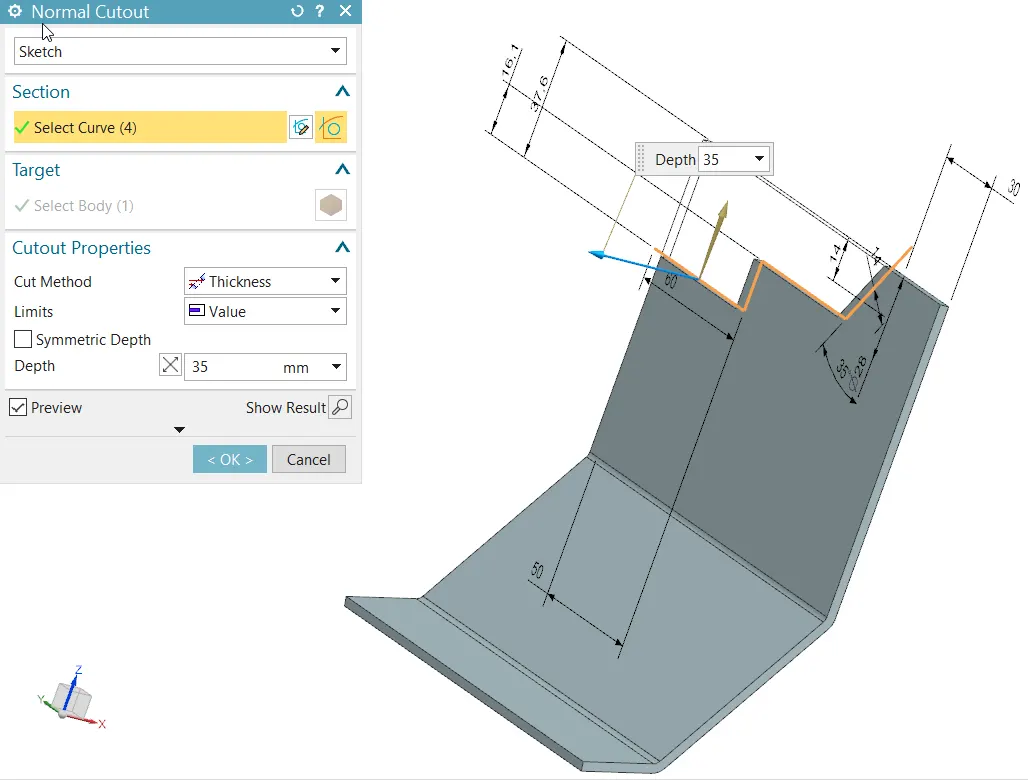
Figure 3: Creating a normal cut-out feature at top left side
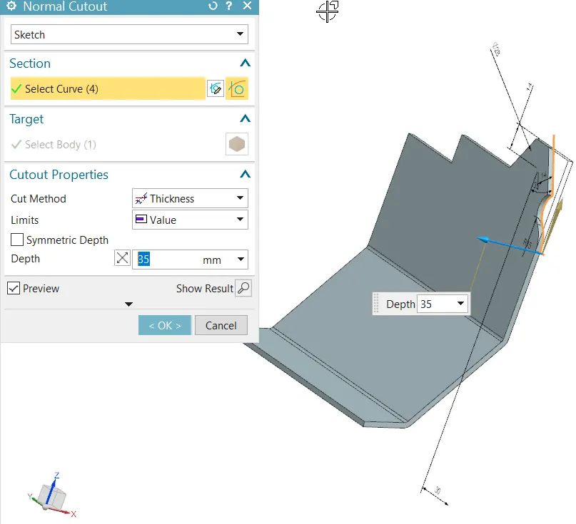
Figure 4: Creating a normal cut-out feature at top right side
After completion of contour flange select the top surface to draw a sketch entity and then use normal cut-out to remove the unwanted portion as shown in figure 3 and figure 4.
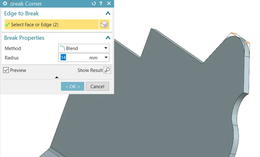
Figure 5(a): Break Corner radius 14mm
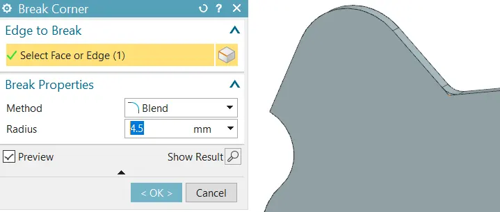
Figure 5(b): Break Corner radius 4.5mm
The above figures show the radius like 14mm and 4.5mm to avoid a sharp edge
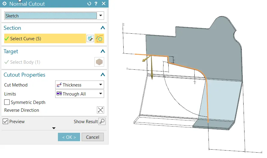
Figure 6: Normal Cut-out at left side
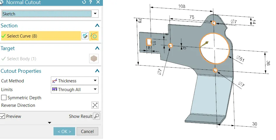
Figure 7: Normal Cut-out to make pocket
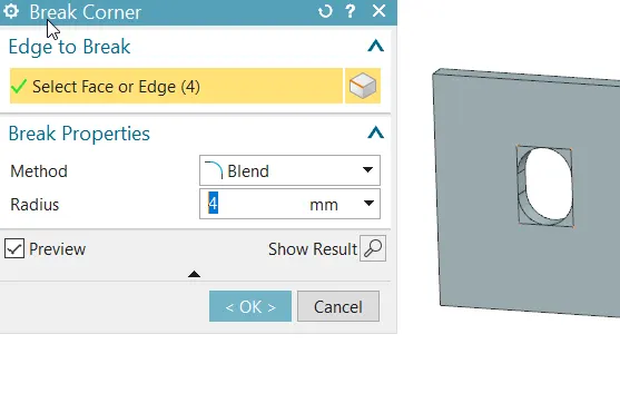
Figure 8: Break Corner radius 4mm
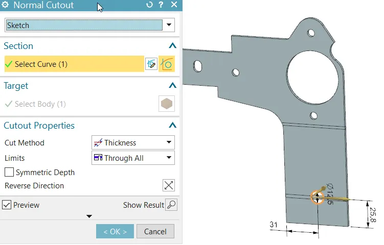
Figure 9: Normal Cut-out
For creating a hole first the feature is unbend and created a hole. After that again rebend to its original position.
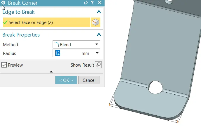
Figure 10: Break Corner radius 12mm
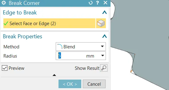
Figure 11: Break Corner radius 5mm
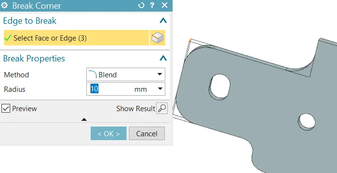
Figure 12: Break Corner radius 10mm
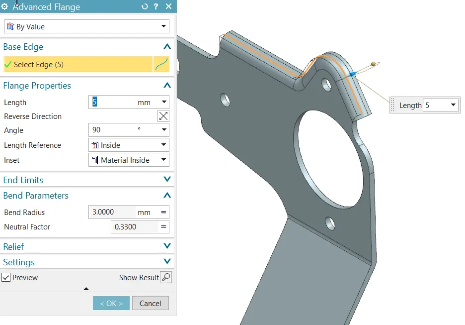
Figure 13: Advanced flange
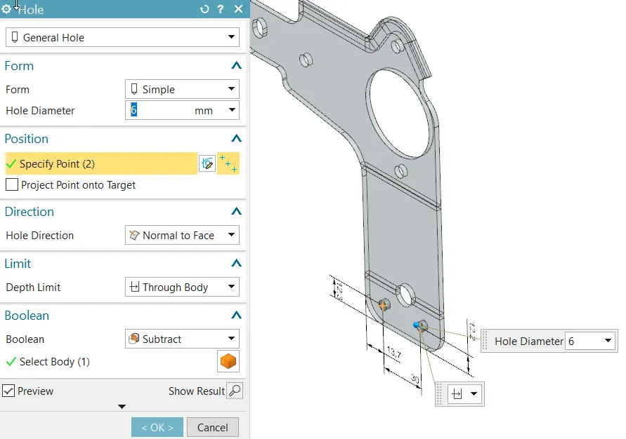
Figure 14: Hole
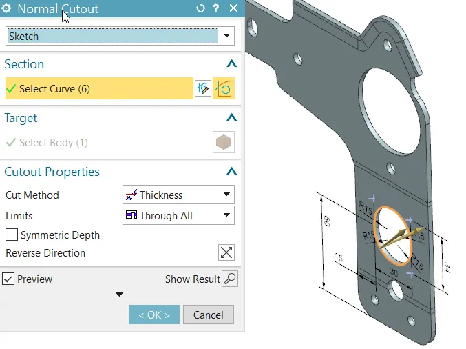
Figure 15: Normal Cut-out
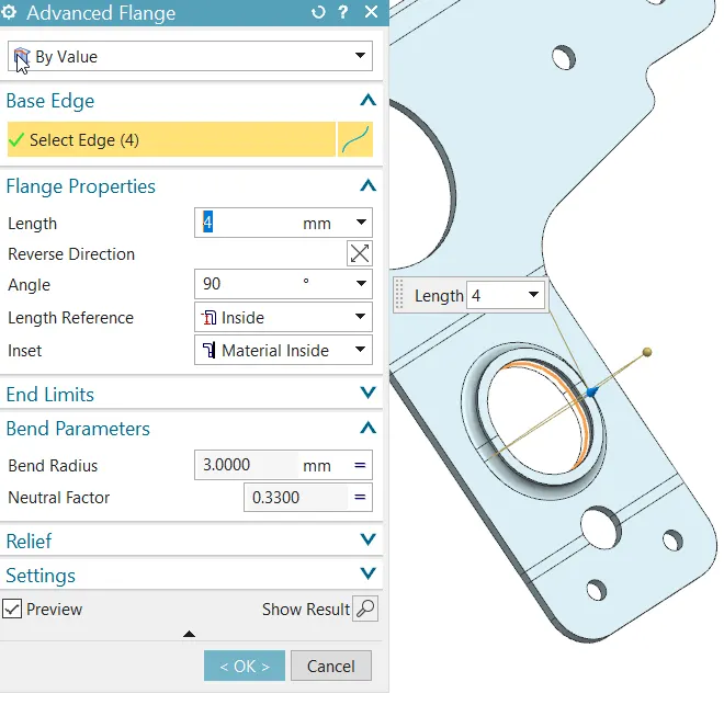
Figure 16: Advanced flange
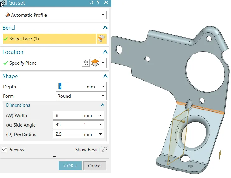
Figure 17: Gusset
Above Figure 17 shows creating a gusset, similarly apply on other end with plane distance 15mm.
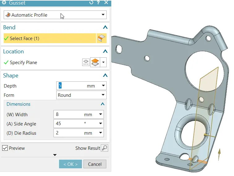
Figure 18: Gusset at bottom
Above Figure 18 shows creating a gusset, similarly apply on other end with plane distance 15mm.
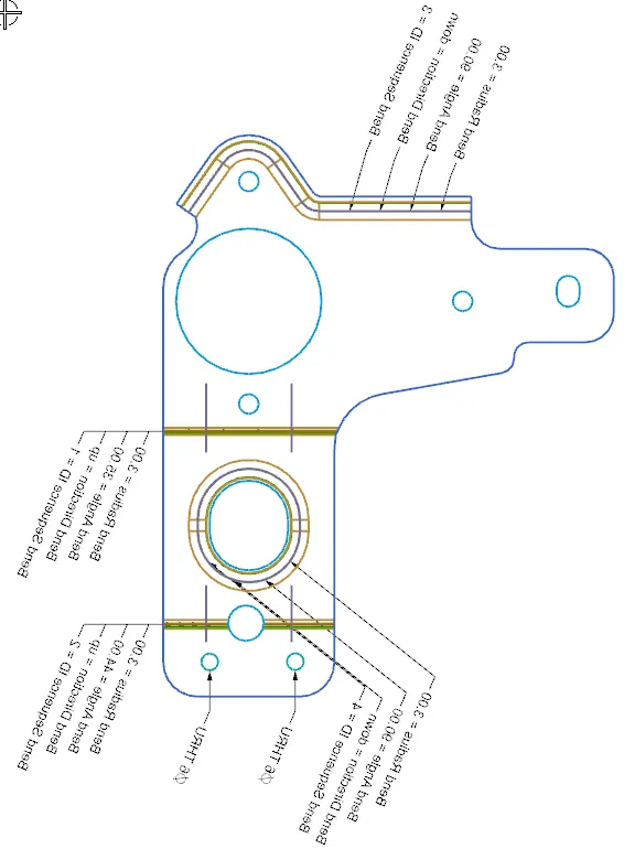
Figure 19: Flat pattern
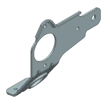
Figure 20: Isometric View
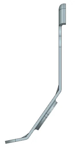
Figure 21: Front View
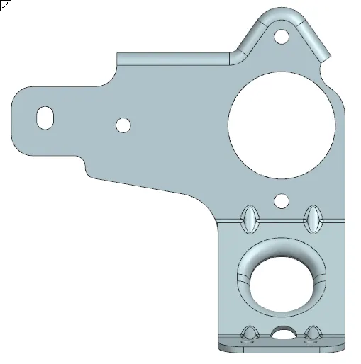
Figure 22: Side View
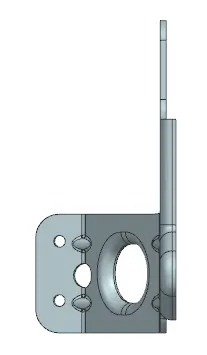
Figure 23: Top View
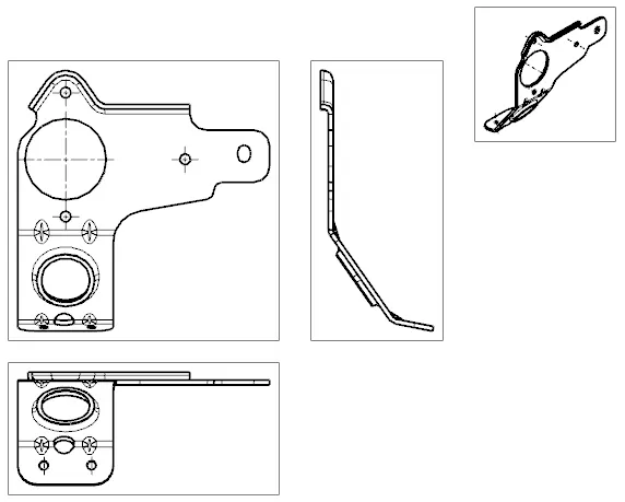
Figure 24: Drafting
Conclusion:
Developed / Created a metal bracket by using NX sheet metal applications.