DESIGN AND ASSEMBLY OF SHEET METAL BOX USING NX CAD
SHEET METAL BOX ASSEMBLY USING NX CAD
OBJECTIVE:
To design and assemble box using sheet metal application in NX CAD.
INTRODUCTION:
NX CAD is a designing software especially focussed on sheet metal applications having numerous methods with easy and precise way to create any sheet metal product. In this project, I have designed a box and assembled in NX CAD.
DESIGN METHODOLOGY/APPROACH:
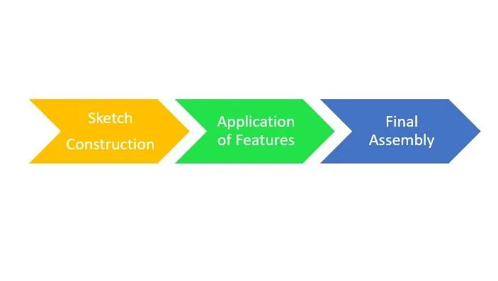
FEATURES:
1. Tab:
This command is used to extrude the 2D sketch connected curves to sheet metal giving appropriate thickness.
2. Flange:
Flange is a extrusion along the edges of the sheet metal part.
3. Closed Corner:
This is used to closed the corner of the ends of two adjacent faces using adjacent bend faces.
4. Hem Flange:
It is used to provide extra strength as well as to keep to sheet metal together without welding application.
5. Mirror Body:
Mirror Body is a feature command used to mirror a body w.r.t plane chosen.
6. Mirror Feature:
This is same as mirror body but with features, its going to be mirroring.
7. Dimple:
This command is used to bump or punch a design on sheet metal which may be used fo grip or sand purpose.
8. Unbend:
This feature is used to flatten the sheet metal
9. Rebend:
This feature is used to get back the original shape of sheet metal after unbending.
10. Bead:
This is used as same as dimple but there is some light difference. It is used to make simple alongside non-cut cutouts.
11. Normal Cutout:
Used to cut the sheet metal using sketches.
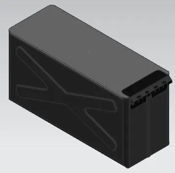
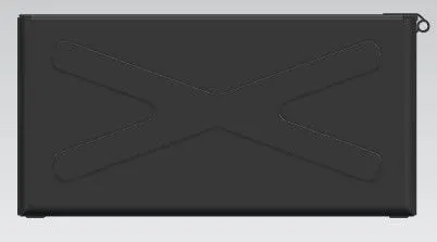
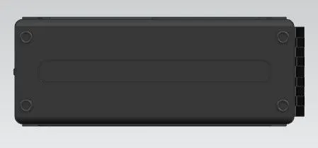
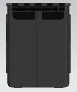
IMAGES OF SHEET METAL BOX ASSEMBLY:
CONCLUSION:
Thus by using NX CAD sheet metal box assembly was sucessfully designed and assembled.