Turbocharger: parts, diagram and how it works
A turbocharger uses the engine's own exhaust to spin a turbine, which drives a compressor that packs more air into the cylinders. Here a small car turbo is modelled in 3D, cut open, pulled apart and run through the exhaust, boost and wastegate stages, with every part labelled.
By Skill-Lync · Published 21 Nov 2026 · Teaching model built and rendered in Blender from code
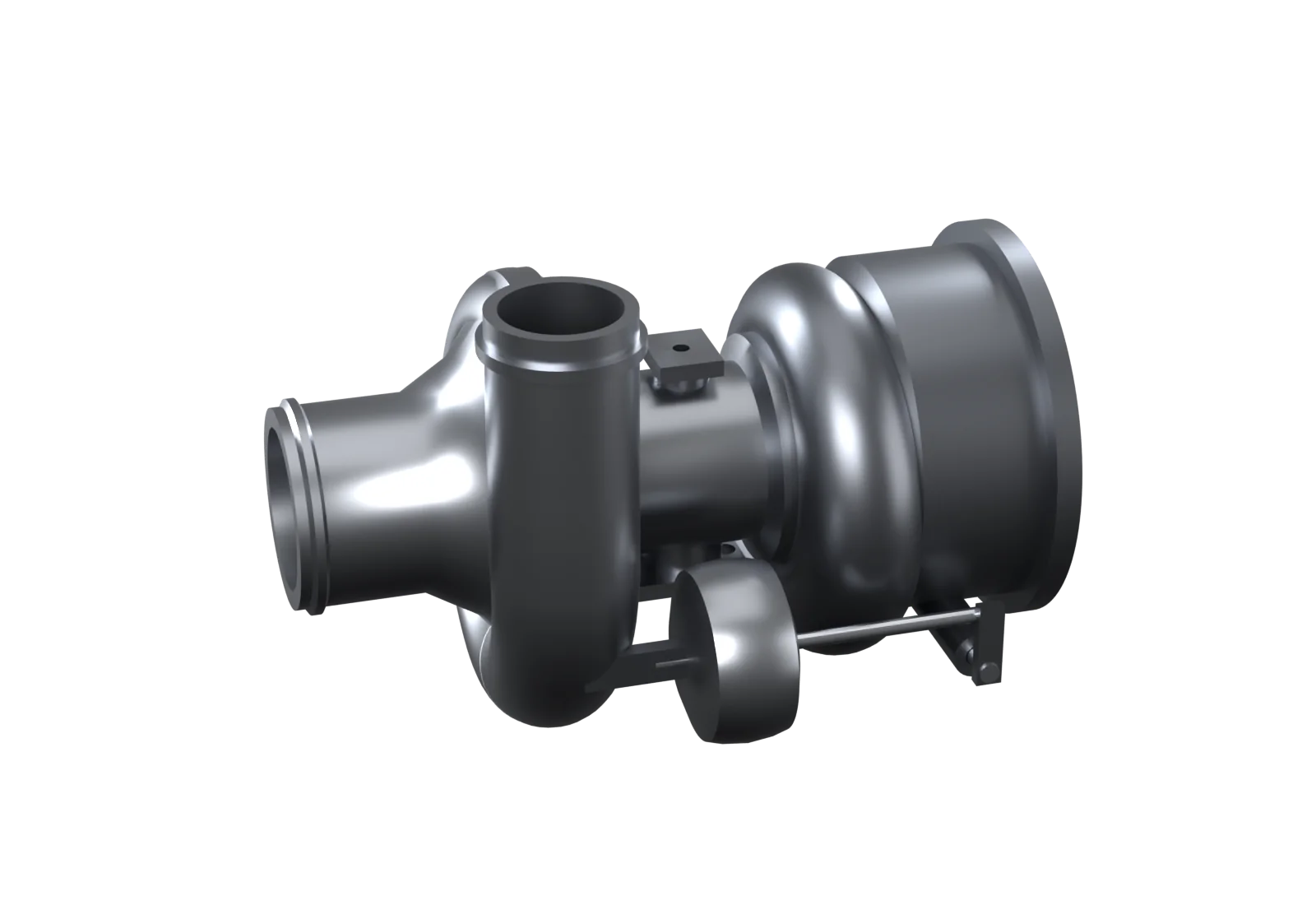
- 1Boost air outlet
- 2Air inlet
- 3Oil drain
- 4Wastegate actuator
- 5Compressor housing
- 6Exhaust outlet
- 7Oil inlet
- 8Turbine housing
- 9Centre (bearing) housing
- 10Actuator rod
- 11Wastegate lever
What is a turbocharger?
A turbocharger is an exhaust-driven air pump for an engine. Exhaust gas spins a turbine wheel; a shaft connects it to a compressor wheel that pressurises the intake air. Denser intake air lets each cylinder burn more fuel, so a small turbocharged engine can make the power of a much larger one.
Think of two fans on one stick. The hot exhaust blows on one fan and makes it spin; the other fan, on the same stick, blows fresh air into the engine. The energy comes from exhaust that would otherwise just leave through the silencer. Swiss engineer Alfred Büchi patented the idea in 1905 (a German patent); today turbochargers are common on petrol as well as diesel car engines.
Speed and density figures come from the worked example on this page and are illustrative, not one product's specification.
What are the parts of a turbocharger and their functions?
A turbocharger has three main sections: the turbine (turbine wheel and turbine housing) on the exhaust side, the compressor (compressor wheel and compressor housing) on the air side, and the centre housing between them, which holds the shaft in oil-fed journal and thrust bearings. A wastegate valve and its actuator control the boost.
Inside a turbocharger: labelled cutaway
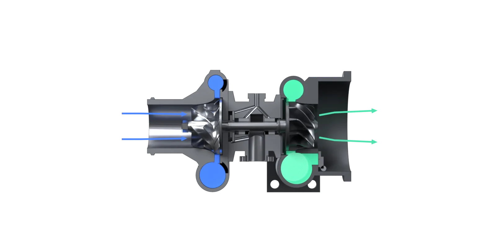
- 1Compressor volute
- 2Back plate
- 3Air inlet
- 4Compressor wheel
- 5Thrust bearing
- 6Fresh air in
- 7Journal bearing
- 8Compressor nut
- 9Diffuser
- 10Turbine volute
- 11Oil feed
- 12Heat shield
- 13Exhaust out
- 14Turbine wheel
- 15Journal bearing
- 16Shaft
- 17Oil drain
- 18Wastegate port
- 19Wastegate valve
| Part | What it does |
|---|---|
| Turbine housing (volute) | A cast snail-shaped housing bolted to the exhaust manifold. Its spiral passage narrows towards the end, so exhaust speeds up and enters the turbine wheel evenly all the way round. |
| Turbine wheel | A radial-inflow wheel cast in a nickel superalloy (Inconel 713C is a common choice) because it runs in exhaust gas at up to about 950 °C. Exhaust flows in at its rim and out along the axis, spinning it. |
| Shaft | Welded to the turbine wheel (electron-beam or friction welding) and carries the compressor wheel, held on by a nut. Turbine and compressor always turn at exactly the same speed. |
| Compressor wheel | An aluminium-alloy wheel with full and shorter splitter blades. It sucks air in along the axis and throws it outward at high speed. |
| Compressor housing, diffuser and volute | The diffuser is the narrow gap around the wheel; the volute is the widening spiral around it. Both slow the air down, turning its speed into pressure, and lead it to the outlet. |
| Centre (bearing) housing | Holds the bearings between the hot turbine and the cool compressor. Oil comes in at the top and drains out at the bottom; some designs also have water-cooling passages. |
| Journal bearings | Two floating bushes that spin freely on films of oil, both between the shaft and the bush and between the bush and the housing. The oil films carry the shaft; metal should never touch metal. |
| Thrust bearing and collar | Take the axial push on the shaft (the turbine and compressor push it in opposite directions by different amounts). Ball-bearing turbos carry this load in the bearing cartridge instead. |
| Piston-ring seals | Split rings, like small piston rings, at each end of the shaft that keep oil in the centre housing and gas out of it. |
| Heat shield and back plate | The heat shield keeps turbine heat away from the bearings; the back plate closes the compressor side and forms one wall of the diffuser. |
| Wastegate valve and port | A flap valve over a hole that connects the turbine inlet straight to the outlet. Opened, it lets part of the exhaust bypass the turbine wheel, which limits boost. |
| Wastegate actuator | A spring-loaded diaphragm canister fed with boost pressure (or an electric motor on newer engines). When boost reaches its setting it pushes the rod and opens the wastegate. |
How does a turbocharger work?
Exhaust gas from the engine flows through the turbine housing and spins the turbine wheel. The shaft turns the compressor wheel at the same speed, which draws in fresh air, compresses it and sends it, usually through an intercooler, to the engine's intake. When boost reaches its limit, the wastegate opens and lets some exhaust bypass the turbine.
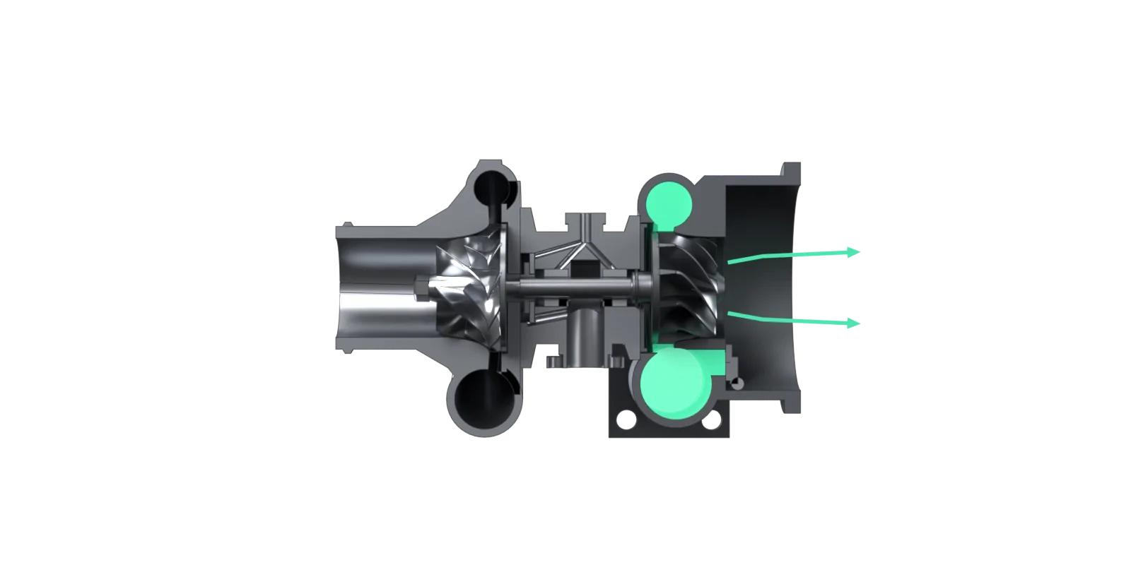
- 1Compressor volute
- 2Compressor wheel
- 3Journal bearing
- 4Turbine volute
- 5Oil feed
- 6Exhaust out to the silencer
- 7Turbine wheel spins
- 8Shaft
- 9Wastegate valve
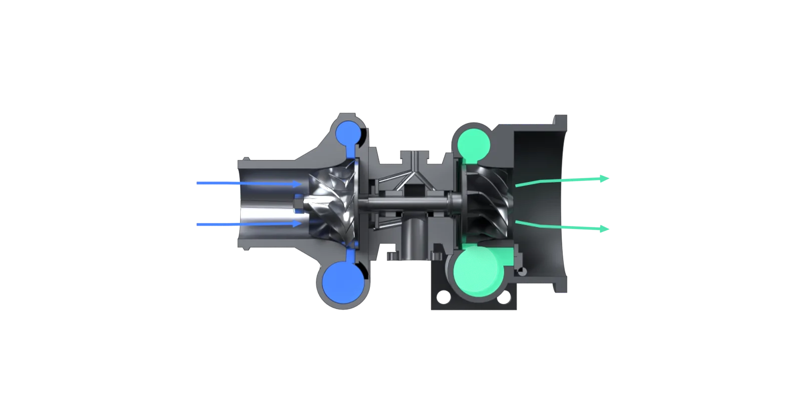
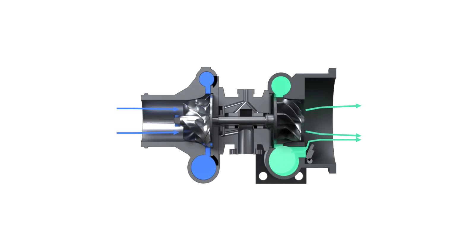
1. Exhaust spins the turbine. Hot exhaust (mint) from the engine enters the turbine housing and spirals round the volute, which narrows so the gas speeds up. It flows inward through the turbine wheel blades and leaves along the axis. Giving up energy to the blades spins the wheel, and the shaft, very fast. This step shows only the exhaust side; the compressor is turning too (next step).
2. Compressor boosts the air. The same shaft turns the compressor wheel. It draws fresh air (blue) in along the axis and flings it outward. The diffuser and the widening volute slow the air down, which turns its speed into pressure. That pressurised air goes through the intercooler to the intake manifold, so each cylinder breathes in more air.
3. Wastegate caps the boost. At high load the turbine could keep spinning faster and over-boost the engine. Boost pressure in the actuator pushes the rod, which swings the wastegate valve open. Part of the exhaust then skips the turbine wheel through the wastegate port, so the turbine speed, and the boost, stop rising.
In a running engine all three happen at once; the steps separate them so you can follow each flow. Arrows show the main flow paths; the gas fills show which passages carry air (blue) and exhaust (mint).
Turbocharger working principle, with numbers
Two textbook relations do most of the work. Compressing air from temperature T₁ by a pressure ratio Π with an isentropic efficiency η heats it to T₂; the power the compressor needs is the air flow times the enthalpy rise, which for a centrifugal wheel is roughly a work coefficient μ times the square of the wheel tip speed U₂ (Euler's turbomachinery equation):
A worked example with round numbers: a 1.5-litre petrol engine at 5,000 rpm (volumetric efficiency 0.90) on a 25 °C day, with the compressor at a pressure ratio of 2.0 (about 1 bar of boost) and an assumed efficiency of 0.72. Then , a 91 K rise where an ideal compressor would add 65 K. An air-to-air intercooler with an effectiveness of 0.65 (Garrett quotes 60-70% for street cars) brings it back to about 57 °C.
| Intake air | Density | vs no turbo | Air flow at 5,000 rpm |
|---|---|---|---|
| Engine without a turbo (25 °C, 1.01 bar) | 1.18 kg/m³ | 1.00× | 67 g/s |
| Turbo, 2.0 bar absolute, no intercooler (116 °C) | 1.82 kg/m³ | 1.53× | – |
| Turbo + intercooler (57 °C) | 2.14 kg/m³ | 1.81× | 120 g/s |
Pushing 120 g/s of air through a 91 K rise takes about 11 kW, all of it carried by a shaft 8 mm thick. With an assumed work coefficient of 0.80, the wheel tip must move at , so a 48 mm wheel spins at . On the other end, 130 g/s of exhaust at 900 °C needs an expansion ratio of only about 1.5 across the turbine to supply that 11 kW (assuming 70% turbine and 95% mechanical efficiency).
Assumed values: volumetric efficiency 0.90, compressor efficiency 0.72, work coefficient 0.80, turbine efficiency 0.70 (total-to-static), mechanical efficiency 0.95, full-load mixture 12.5:1, exhaust at 900 °C. Intercooler and air-filter pressure losses are ignored, and the turbine figure assumes the wastegate is shut. Real efficiencies come from the manufacturer's maps and change across the operating range. Every number here is checked by a script kept with the model files.
Turbocharger exploded view: how the parts fit together
The compressor housing and turbine housing are clamped to either end of the centre housing, with the back plate on the compressor side and the heat shield on the turbine side. The rotating assembly comes out as one group: the turbine wheel and its welded shaft, the thrust collar and journal bearings on the shaft, and the compressor wheel held on by its nut.
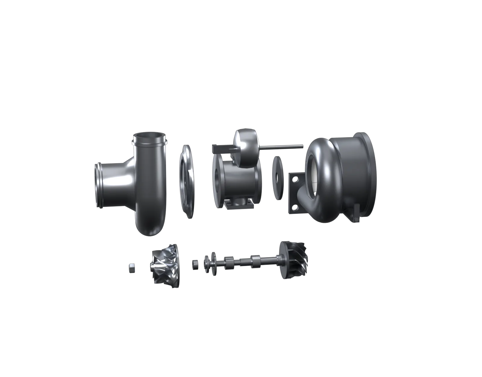
- 1Compressor housing
- 2Back plate
- 3Centre housing
- 4Wastegate actuator
- 5Heat shield
- 6Turbine housing
- 7Nut
- 8Compressor wheel
- 9Thrust collar and bearing
- 10Journal bearings
- 11Turbine wheel and shaft
- 12Wastegate lever and spindle
Turbocharger dimensions: front and inlet-end views
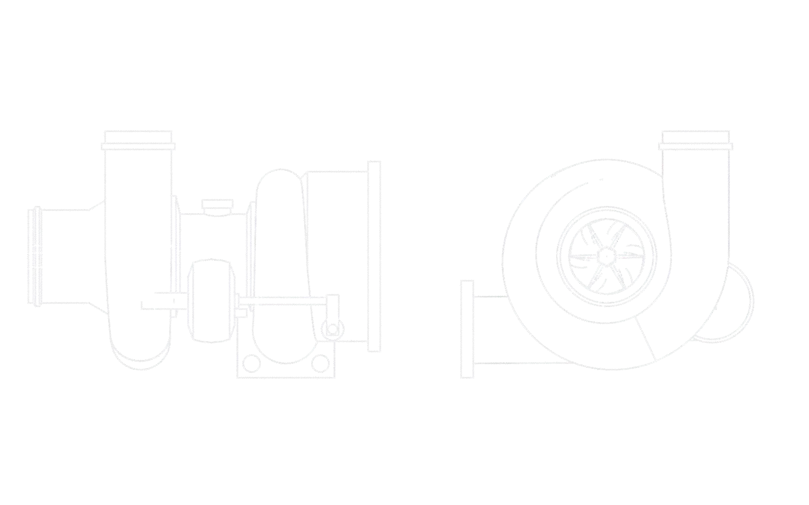
| Dimension | Value | Basis | |
|---|---|---|---|
| A | Overall length, air inlet to exhaust outlet flange | 174 mm | This model |
| B | Overall height, compressor outlet to turbine inlet flange | 122 mm | This model |
| C | Compressor wheel inducer (inlet) diameter | 36 mm | This model; Garrett's GBC17-250 small-engine turbo uses 36 mm |
| – | Compressor wheel exducer (outer) diameter | 48 mm | This model; GBC14-200: 46 mm, GBC17-250: 49 mm |
| – | Turbine wheel inducer / exducer diameter | 42 / 37 mm | This model; GBC14-200: 39 / 36 mm, GBC17-250: 44 / 40 mm |
| – | Shaft journal diameter | 8 mm | This model |
What are the types of turbochargers?
Turbochargers differ mainly in how boost is controlled (wastegate or variable-geometry turbine), how the exhaust is fed in (single-scroll or twin-scroll), how many are used (single, twin or sequential) and the bearing system (oil-fed journal bearings or a ball-bearing cartridge). Small car engines mostly use a single wastegated or twin-scroll turbo.
| Type | How it works | Why use it |
|---|---|---|
| Wastegated (this model) | A valve bypasses exhaust around the turbine once boost reaches its limit; internal (built into the turbine housing) or external (a separate valve on the manifold) | Simple and cheap; the most common type on petrol cars |
| Variable geometry (VGT / VNT) | A ring of movable vanes around the turbine inlet changes the gas angle and speed: narrow for quick spool-up, open for high flow | Less lag and a wider boost range. Long used on diesels; Porsche says its 2006 911 Turbo was the first series petrol engine with VTG |
| Twin-scroll | The turbine housing has two inlet passages, each fed by cylinders that don't fire one after another (1 and 4, 2 and 3 on a 1-3-4-2 engine) | Cleaner exhaust pulses reach the turbine, so it spools up faster |
| Twin-turbo / sequential | Two turbos, one per cylinder bank, or a small one for low speed and a large one that joins in higher up | Quick response and high peak power |
| Ball-bearing turbo | The shaft runs in an angular-contact ball-bearing cartridge instead of floating journal bushes; it also carries the thrust load | Lower friction, so faster spool-up |
| Water-cooled centre housing | Coolant passages around the bearings, in addition to the oil | Protects the oil from coking after a hot shutdown |
Turbo wastegate: function and actuator
The wastegate keeps boost at its target. Without it, exhaust flow keeps rising with engine speed and load, the turbine keeps speeding up, and boost would climb past what the engine can take. The wastegate valve opens a path from the turbine inlet straight to the outlet, so the extra exhaust skips the wheel.
In this model the actuator is a canister with a spring-loaded diaphragm, connected by a hose to the compressor outlet. When boost pressure on the diaphragm beats the spring, the rod pushes the lever, the spindle turns and the valve swings open. On many modern engines the ECU controls the actuator through a solenoid valve or uses an electric actuator, so boost can be set for each operating point. A wastegate stuck shut causes over-boost; one stuck open, a lack of power; a worn linkage often rattles.
Turbocharger vs supercharger: which is better?
A turbocharger is more efficient because it runs on exhaust energy that would otherwise be wasted, which is why it is the usual choice for downsized engines that cut fuel use and emissions. A supercharger is driven mechanically from the crankshaft, so it gives instant boost without lag, but it takes engine power to drive it.
| Turbocharger | Supercharger | |
|---|---|---|
| Driven by | Exhaust gas through a turbine | Belt, chain or gears from the crankshaft |
| Efficiency | Recovers exhaust energy | Uses engine power to drive it |
| Response | Some lag while the turbine spools up | Instant, tied to engine speed |
| Heat and oil | Runs very hot; needs oil feed and drain | Cooler; often self-contained lubrication |
| Typical use | Petrol and diesel cars, trucks, ships | Some performance cars, drag racing, older aircraft engines |
Common turbocharger problems and their symptoms
Garrett says most turbo failures come from three causes: oil starvation, oil contamination and foreign object damage. Look out for a sharp rise in noise, visible exhaust smoke and a lack of power.
| Problem | Cause | What you notice |
|---|---|---|
| Oil starvation | Low oil level or pressure, blocked feed pipe, hot shutdowns coking the oil | Bearing wear, shaft play, wheels rubbing their housings, whining noise |
| Oil contamination | Dirty or old oil, missed oil changes, wrong filter | Scored bearings and shaft; failure that looks like starvation |
| Foreign object damage | Debris through a torn air filter or from the engine | Chipped or bent blades, a siren-like noise, loss of boost |
| Oil leaking past the seals | Blocked or kinked oil drain, high crankcase pressure, worn seal rings | Smoke from the exhaust, oil in the intercooler pipes |
| Wastegate faults | Seized valve, split actuator diaphragm, worn linkage | Over-boost (stuck shut) or low boost and power (stuck open), rattle |
Where are turbochargers used?
In many modern car engines, both petrol and diesel, where a smaller turbocharged engine replaces a larger one for the same power with lower fuel use. Also in trucks, buses, tractors, ships, locomotives, diesel generators and piston aircraft engines, where turbos also make up for thinner air at altitude.
Turbocharger interview and viva questions
Why is an intercooler fitted after the compressor?
Compressing air heats it: in our example from 25 °C to about 116 °C. Hot air is less dense and makes knock more likely in a petrol engine. Cooling it back to about 57 °C raises the density by another 18% at the same boost pressure (from 1.82 to 2.14 kg/m³ in the example).
Why are the turbine and compressor wheels made of different materials?
The turbine wheel runs in exhaust gas at up to about 950 °C, so it is cast in a nickel superalloy such as Inconel 713C that stays strong when hot. The compressor wheel sees air at about 100-200 °C, so it can be aluminium, which is light and reduces the inertia that causes turbo lag.
Why does the compressor volute get bigger towards the outlet while the turbine volute gets smaller?
The compressor volute collects air leaving the diffuser all the way round the wheel, so its flow grows along the spiral and its area grows with it. The turbine volute does the opposite: it feeds gas into the wheel all the way round, so the flow left in it shrinks and its area shrinks to keep the gas speed even.
Why must you not switch off a hot turbo engine immediately after hard driving?
The oil pump stops with the engine, but the turbine and its housing are still very hot. Oil sitting in the hot centre housing can break down into hard carbon deposits (coking) that block the oil passages and starve the bearings later. Letting the engine idle briefly lets the turbo cool while oil is still flowing.
What is a twin-scroll turbocharger?
A turbine housing with two separate inlet passages. On a four-cylinder engine with firing order 1-3-4-2, cylinders 1 and 4 share one scroll and 2 and 3 the other, so exhaust pulses from consecutive cylinders don't interfere. The turbine gets cleaner pulses and spools up faster.
About this 3D model
This is a teaching model of a small passenger-car turbocharger, not a CAD replica of a product. Its wheel sizes follow Garrett's small-engine turbos (a 36/48 mm compressor wheel and a 42/37 mm turbine wheel), with floating journal bearings, a thrust bearing, an internal wastegate and a pneumatic actuator. Simplifications: the turbine inlet is drawn round instead of the usual rectangular or oval section, there is no water jacket, the compressor's anti-surge features and the blow-off valve are left out, and the housings are clocked to show the parts clearly. Skill-Lync modelled and rendered it in Blender entirely from code, so it can be checked and re-rendered.
Related Skill-Lync courses and reading
- IC Engine Calibration using GT-POWER and GT-SUITEEngine and turbocharger models, boost and wastegate control, and the maps calibration engineers tune.
- Advanced Turbomachinery SimulationsCFD of compressor and turbine wheels: blade passages, performance maps and losses.
- Internal Combustion Engine Analyst course using Python and CanteraEngine cycles, charge density and combustion, worked in Python.
- Advanced CFD for IC Engine Applications using CONVERGESimulate intake flow, mixing and combustion inside a boosted engine.
- Automobile engineering book, chapter 9: turbochargers and superchargers
- How turbochargers boost engine efficiency (CFD)
- An introduction to turbomachinery
- How an IC engine works: four strokes and real engine numbers
- Carburetor in 3D: parts, cutaway and how it works
- Fuel injector in 3D: parts, cutaway and how it works
- Disc brake in 3D: parts, caliper cutaway and how it works
- More parts in 3D: all engineering components
FAQs
What are the main parts of a turbocharger?
A turbocharger has a turbine wheel in a turbine housing, a compressor wheel in a compressor housing, and a shaft joining them that runs in a centre (bearing) housing. The centre housing holds the journal bearings, a thrust bearing and the seals, with an oil feed and drain. Most car turbos add a wastegate valve and its actuator to limit boost.
What is the working principle of a turbocharger?
A turbocharger recovers energy from the engine's exhaust. Exhaust gas spins a turbine wheel, and the shaft drives a compressor wheel that pressurises the intake air. Denser air means more oxygen in each cylinder, so more fuel can be burned and the engine makes more power for its size.
How fast does a turbocharger spin?
Very fast, and the smaller the turbo, the faster. Garrett says turbochargers can rotate at more than 300,000 rpm depending on size; Mitsubishi rates its small TD02 at 260,000 rpm and the larger TD04 at 190,000 rpm. Our worked example, a 48 mm compressor wheel giving 1 bar of boost, comes out at about 134,000 rpm.
What does a wastegate do in a turbo?
A wastegate limits boost. It is a valve that lets part of the exhaust bypass the turbine wheel. When boost reaches the set level, the actuator opens the valve, the turbine stops speeding up, and boost stays at the target instead of rising until the engine or the turbo is damaged.
What is turbo lag?
The delay between pressing the accelerator and the boost arriving. At low engine speed there is little exhaust energy, and the rotating parts need time to speed up. Smaller, lighter wheels, twin-scroll housings, variable-geometry turbines, ball bearings and electric assistance all reduce it.
What is the difference between a turbocharger and a supercharger?
Both compress the intake air. A turbocharger is driven by exhaust gas, so it uses energy that would otherwise be wasted, but it can lag. A supercharger is driven by a belt or gears from the crankshaft, so it responds instantly, but it takes power from the engine to turn.
Why do turbochargers fail?
Garrett says most failures come from three causes: oil starvation, oil contamination and foreign objects getting into the wheels. Typical signs are a sharp rise in noise, visible exhaust smoke and a lack of power.
Sources
- Garrett Motion: Turbo Tech 101 (Basic) (parts, full-floating journal bearings and thrust bearing, ball-bearing cartridges, wastegates and actuators)
- Garrett Motion: Why do turbochargers fail? (oil starvation, oil contamination, foreign object damage; symptoms)
- Garrett Boost Club small-engine turbochargers (compressor and turbine wheel sizes used for this model's proportions)
- Mitsubishi Heavy Industries: turbocharger technical information (maximum speeds and gas temperatures by model)
- Porsche: 997 Turbo (first series petrol engine with variable turbine geometry, 2006) · Accelleron: 100 years of industrial turbocharging (Alfred Büchi's 1905 patent)
- J. B. Heywood, Internal Combustion Engine Fundamentals, McGraw-Hill, chapter 6 (turbocharging): compressor and turbine work, intercooling