Modified on
How Do IC Engines Work?

Skill-Lync
So you're a car enthusiast, and you’ve always wondered how a car’s Internal Combustion (IC) engine works. These engines are used in most vehicles that use fuel. The IC is a marvel of modern engineering. It helps us transition from a labour-first economy to a machine-first economy, enabling us to do more with less.
In this blog, we’ll look at how an IC engine works, from the basics of combustion to the complex systems that make it run.
_1679060146.png)
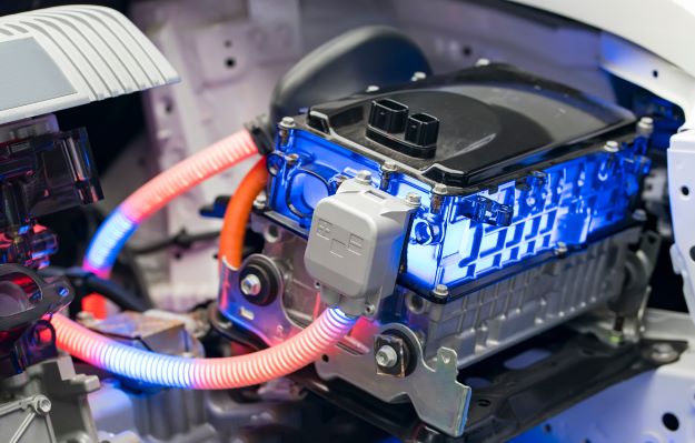
Introduction to IC Engine
The first Internal Combustion Engine, or ICE, was built by John Stevenson in 1798. ICEs are heat engines that convert fuel into mechanical energy by combustion within an enclosed space. A spark plug typically powers this combustion process, and the resulting energy is used to move a piston, which powers the vehicle.
The internal combustion engine is the most common type of engine used today,
- Cars
- Motorbikes
- Trucks
Components of an IC Engine
An internal combustion engine is a complex machine that uses many components to function properly. The most important components of an IC engine include,
- Cylinder block
- Piston
- Piston rings
- Connecting rods
- Combustion chamber
- Seals
- Crankshaft
- Cams and Camshaft
- Flywheel
- Fuel Injector
- Spark plug
Cylinder block
- The cylinder block is the primary component of an IC engine.
- It is also referred to as an engine block.
- An engine block is a primary support component that holds and supports the other engine components.
_1679060237.png)
Piston
- The piston is a tubular component inside the engine cylinder.
- Inside the cylinder, the piston is restricted to one-side motion.
- It is a part of the engine’s combustion chamber that creates mechanical power by converting the forces produced from the exhaust gas into a reciprocating motion.
- It forms the lower part of the combustion chamber.
Piston rings
- Piston rings provide an airtight seal between the piston and the cylinder wall.
- It helps transfer heat to the walls of the cylinder and lubricate and push oil out of it.
Connecting rods
- Connecting rods are used to connect the piston to the crankshaft.
- A gudgeon pin connects the smaller end to the piston, and the bigger end is connected to the crankshaft by a crankpin.
Combustion chamber
- It is the space between the piston and the cylinder during the combustion process.
- During fuel combustion, thermal energy is released by the expanding gases, which cause pressure to build up in the chamber. This pressure moves the piston.
_1679061544.png)
Seals
- Seals protect the bearings and prevent gas and oil from leaking outside the cylinder.
Crankshaft
- It is a component that converts the piston's reciprocating motion to the output shaft's rotary motion.
- Bearings are used to reduce friction and allow it to move freely,
Cams and Camshaft
- Cams and Camshafts control the exhaust and inlet valves' opening and closing.
- They are driven by a crankshaft and are programmed to open, stay open, and close at very precise times.
Flywheel
- The flywheel is a mass attached to the output shaft to perform uniform torque and minimise the fluctuation in angular velocity.
_1679061600.png)
Fuel Injector
- Fuel injectors spray the fuel through a tiny nozzle into the combustion chamber.
- When the throttle is opened, the fuel is first mixed with the air, and then it is sprayed into the combustion cylinders.
Spark plug
- The spark plug is the component which is located at the cylinder head and is used to initiate the combustion process by ignition.
Working Principle of IC Engines
The IC engine is a heat engine in which fuel combustion occurs with an oxidiser (usually air) in a combustion chamber. The heat energy released by burning fuel is converted into mechanical energy used to power the engine. The four-stroke IC engine is the most common engine used in automobiles today. It works by using the four strokes to convert the chemical energy of the fuel into mechanical energy. which are,
The Intake Stroke
- The intake stroke begins when the piston moves downward, drawing air and fuel into the cylinder.
The Compression Stroke
- During the compression stroke, the piston moves upward and compresses the air-fuel mixture.
- This increases the temperature and pressure of the mixture, making it more combustible.
The Combustion Stroke
- The combustion stroke begins when the spark plug ignites the pressurised mixture of air and fuel, causing it to burn.
- The burning fuel creates a high-pressure force that pushes the piston downward, creating mechanical energy.
The Exhaust Stroke
- The exhaust stroke begins when the piston moves upward, pushing the exhaust gases out of the cylinder.
- This completes the cycle, and the engine is ready to start the next cycle.
Four-stroke IC engines are a reliable and efficient way to convert fuel into mechanical energy. It is used in various applications, from cars to lawnmowers, and is the most common engine used in automobiles today.
_1679061665.png)
Systems Involved in an IC Engine
- Fuel system
- The fuel system is responsible for delivering the fuel to the engine.
- This is usually done by the fuel pump, which draws the fuel from the fuel tank and sends it to the engine.
- The fuel is then mixed with air in the carburettor, which helps to create a combustible mixture.
- Air intake system
- The air intake system supplies the engine with air.
- This is usually done by an air filter, which filters out dust and other particles from the air before it enters the engine.
- Ignition system
- The ignition system is responsible for igniting the fuel-air mixture in the engine.
- This is done by the spark plug, which creates a spark to ignite the fuel mixture.
- Exhaust system
- The exhaust system is responsible for removing exhaust gases from the engine.
- This is done by an exhaust manifold, which collects the exhaust gases and directs them out of the engine.
- Cooling system
- The cooling system is responsible for keeping the engine cool.
- The radiator is the main component which keeps the engine cool. It circulates coolant through the engine to keep it from overheating.
- Lubrication system
- The lubrication system keeps the engine's moving parts smooth and without friction.
- Oil is the most commonly used lubricant in ICEs.
Conclusion
By understanding how an internal combustion engine works, we can better appreciate its capabilities and limitations. To learn more about the engines and similar topics, check out our courses, such as the Post Graduate Program in Hybrid Electric Vehicle Design and Analysis and Electric Vehicle Design & Development. Skill-lync offers courses exclusively for engineering graduates to upskill their careers to the next level. Talk with our experts for more information!
Author

Navin Baskar
Author
Skill-Lync
Subscribe to Our Free Newsletter

Continue Reading
Related Blogs
Learn how to render a shock-tube-simulation and how to work on similar projects after enrolling into anyone of Skill-Lync's CAE courses.
09 May 2020
In this blog, read how to design the frontal BIW enclosure of a car (Bonnet) and learn how Skill-Lync Master's Program in Automotive Design using CATIA V5 will help you get employed as a design engineer.
09 May 2020
Tetrahedral is a four- nodded solid element that can be generated through the tria element by creating a volume and also through the existing volume of the geometry. These elements are used where the geometry has high thickness and complexity. The image attached below is a representation of a Tetra element. The Tetra element will have 4 triangular faces with four nodes joining them together
01 Aug 2022
A connector is a mechanism that specifies how an object (vertex, edge, or face) is connected to another object or the ground. By often simulating the desired behaviour without having to build the precise shape or specify contact circumstances, connectors make modeling simpler.
02 Aug 2022
One of the most crucial processes in carrying out an accurate simulation using FEA is meshing. A mesh is composed of elements that have nodes—coordinate positions in space that might change depending on the element type—that symbolise the geometry's shape.
03 Aug 2022
Author
Skill-Lync
Subscribe to Our Free Newsletter
Continue Reading
Related Blogs
Learn how to render a shock-tube-simulation and how to work on similar projects after enrolling into anyone of Skill-Lync's CAE courses.
09 May 2020
In this blog, read how to design the frontal BIW enclosure of a car (Bonnet) and learn how Skill-Lync Master's Program in Automotive Design using CATIA V5 will help you get employed as a design engineer.
09 May 2020
Tetrahedral is a four- nodded solid element that can be generated through the tria element by creating a volume and also through the existing volume of the geometry. These elements are used where the geometry has high thickness and complexity. The image attached below is a representation of a Tetra element. The Tetra element will have 4 triangular faces with four nodes joining them together
01 Aug 2022
A connector is a mechanism that specifies how an object (vertex, edge, or face) is connected to another object or the ground. By often simulating the desired behaviour without having to build the precise shape or specify contact circumstances, connectors make modeling simpler.
02 Aug 2022
One of the most crucial processes in carrying out an accurate simulation using FEA is meshing. A mesh is composed of elements that have nodes—coordinate positions in space that might change depending on the element type—that symbolise the geometry's shape.
03 Aug 2022
Related Courses