Modified on
What Goes Into Remastering A Non-Parametric Body Into A Parametric Body?

Skill-Lync
Remastering is a topic that comes under reverse engineering topics. Remastering is a technique that is used to create proper parametric bodies from non-parametric bodies. The remastering can be divided into two, based on the procedures that we follow to create a parametric body, i.e. surface and part remastering. In this article, we discuss the process of remastering. Keep in mind that the explanation below is a simple example to make you understand what is meant by remastering and its basic procedures. Advanced remastering procedures will be covered in separate articles.
Situations where remastering is performed
If we need to develop/modify a new design from our parent/old design when we only have the dump/non-parametric version of our old design; we need to create the parametric version of the old design(same design) using remastering. Remastering must only be performed if we do not have a parametric version of the old design. So after getting a fully dimensioned parametric body of the old design, later we can use the model and edit the values accordingly based on the new changes and requirements.
Example:
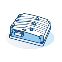
Let's take the same model that we previously worked on.
_1670059439.png)
Let's imagine that we only have this model available and that too in a non-parametric/dump form. So we use a remastering process to recreate this same model into a parametric body with all the dimensions and operations available.
Now for recreating this model first we need to make sure we need to modify the dump body into its simpler form. For that let’s temporarily remove the fillet for now. For removing the fillet, we have already learned two different tools in the previous session.
So let's see if we can remove the fillet using deactivate mode.
_1670059488.png)
When we search for deactivation, that option is not available for the dump body. So now we only have one option i.e, remove the face option.
In order to perform easy remastering, it will be better if we temporarily remove the entire fillet face option for now.
_1670059526.png)
_1670059557.png)
Let's rename the body “non_parametric_,body”, insert a new body, and rename it as parametric_working_model.
_1670059596.png)
Working on the newly inserted body during Remastering
First, let's take the top plane and create a new sketch. Let's then project the dump body into this new sketch using the project 3d element. Before going with these steps, I need to discuss an important rule of remastering. The newly created parametric body should not be having any relation with the non-parametric/dump body. So while projecting the model using the project 3d element we need to make sure that we are isolating it properly using Create Datum and then project it.
_1670059641.png)
By doing this we are completely removing the relation between the sketch and the dump body.
_1670059675.png)
Since we broke the relation, now we want to constrain it properly from the origin(horizontal/vertical).
_1670059711.png)
By doing this we now know the length and breadth of our model. Let exit the sketch and move on to the pad operation.
_1670059746.png)
Again we are not aware of the height of the body in mm because it's a dump body. But we previously learned that with the measure between and measure item option from the pad, we can easily find the height of a dump body.
Let's define the body Parametric_working_model.
_1670059787.png)
By doing that we can put our new parametric model inside the body parametrci_working_model.
First, select the pad operation and then select the new sketch.
_1670059824.png)
Right-click on the length and go with the measure between options.

Now select the two opposite faces to measure the height of the body.

Uncheck the keep measure and click ok.
Click ok to pad definition as well.
Just for understanding purposes, let's change the color of the dump body. For that right-click and select the properties. From there, select the graphic and choose a suitable color.

Let's hide the parametric_working_model for now. Also, let's remove the remove face option by deleting removeface. one from the tree.

Now, let's unhide the working model, and we may need to add the fillet onto the top edge.

Let's hide the working model again and measure the fillet value using the measure item option by clicking any one of the fillet faces.

Now we know that the fillet value is 15mm. Cancel the option and add the fillet over the new working model edge with a value of 15mm.

Now we have our final result.

By this, we made our new parametric body an exact copy of the dump body.
Sometimes we need to figure out how closely we have achieved our final result using the remastering technique. For that, there is a separate tool called deviation analysis.

Deviation Analysis
Deviation analysis helps us to understand the volume difference between the non-parametric and parametric bodies. If the maximum and minimum deviation values are more than what we require, again, we need to work on the highlighted area and make it closer to our requirement.
For invoking Deviation Analysis, go to Start -> Shape-> Quick Surface Reconstruction
From there Go to Insert-> Analysis-> Deviation Analysis.

First, select the non-parametric body as the reference.

To measure, select the last operation done for the newly created body from the tree. Here it is Edgefillet.1.

Click apply and OK.
Here we can see that the Positive deviation between the parametric and non-parametric body is 0 and the negative deviation is -0.00947 which is again closer to 0. This means that the difference between our parametric and non-parametric bodies is null. Hence, we were able to create a Parametric identical body from the non-parametric one.


Author

Navin Baskar
Author
Skill-Lync
Subscribe to Our Free Newsletter

Continue Reading
Related Blogs
Learn how to render a shock-tube-simulation and how to work on similar projects after enrolling into anyone of Skill-Lync's CAE courses.
09 May 2020
In this blog, read how to design the frontal BIW enclosure of a car (Bonnet) and learn how Skill-Lync Master's Program in Automotive Design using CATIA V5 will help you get employed as a design engineer.
09 May 2020
Tetrahedral is a four- nodded solid element that can be generated through the tria element by creating a volume and also through the existing volume of the geometry. These elements are used where the geometry has high thickness and complexity. The image attached below is a representation of a Tetra element. The Tetra element will have 4 triangular faces with four nodes joining them together
01 Aug 2022
A connector is a mechanism that specifies how an object (vertex, edge, or face) is connected to another object or the ground. By often simulating the desired behaviour without having to build the precise shape or specify contact circumstances, connectors make modeling simpler.
02 Aug 2022
One of the most crucial processes in carrying out an accurate simulation using FEA is meshing. A mesh is composed of elements that have nodes—coordinate positions in space that might change depending on the element type—that symbolise the geometry's shape.
03 Aug 2022
Author
Skill-Lync
Subscribe to Our Free Newsletter
Continue Reading
Related Blogs
Learn how to render a shock-tube-simulation and how to work on similar projects after enrolling into anyone of Skill-Lync's CAE courses.
09 May 2020
In this blog, read how to design the frontal BIW enclosure of a car (Bonnet) and learn how Skill-Lync Master's Program in Automotive Design using CATIA V5 will help you get employed as a design engineer.
09 May 2020
Tetrahedral is a four- nodded solid element that can be generated through the tria element by creating a volume and also through the existing volume of the geometry. These elements are used where the geometry has high thickness and complexity. The image attached below is a representation of a Tetra element. The Tetra element will have 4 triangular faces with four nodes joining them together
01 Aug 2022
A connector is a mechanism that specifies how an object (vertex, edge, or face) is connected to another object or the ground. By often simulating the desired behaviour without having to build the precise shape or specify contact circumstances, connectors make modeling simpler.
02 Aug 2022
One of the most crucial processes in carrying out an accurate simulation using FEA is meshing. A mesh is composed of elements that have nodes—coordinate positions in space that might change depending on the element type—that symbolise the geometry's shape.
03 Aug 2022
Related Courses