Ackermann's Principle of Steering: Formula, Working and Worked Example
Why the inner front wheel must steer more than the outer: Ackermann's condition for correct steering derived, worked through with a Suzuki Swift's published dimensions, how the trapezoid linkage approximates it (percentage Ackermann), Davis vs Ackermann steering gear, anti-Ackermann and where it is used.
In short
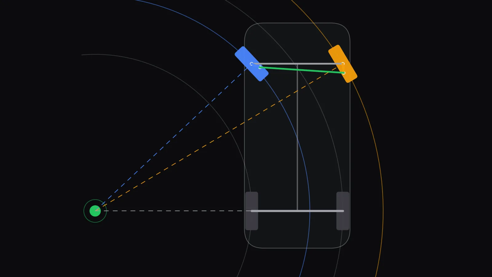
- Ackermann's principle of steering: when a car turns, the axes of all its wheels should pass through one point, the turn centre. That way every tyre rolls without being dragged sideways. Because the inner front wheel runs on a smaller circle, it must steer more than the outer one.
- The condition for correct steering is , where is the distance between the steering pivots and is the wheelbase.
- Worked example with Suzuki's published Swift figures (2,450 mm wheelbase, 1,520 mm front tread, 4.8 m minimum turning radius): at full lock the inner wheel needs about 43.2° and the outer wheel about 30.7°, a 12.5° difference.
- A four-bar trapezoid linkage only approximates this. In Skill-Lync's calculation for the same car, aiming the steering arms at the rear-axle centre left the outer wheel up to 2.2° off. Steeper 24° arms kept the error within 0.4° up to a 33° inner angle.
Ackermann's principle of steering says that, in a turn, the front wheels must point at different angles so that lines drawn through all four wheel axles meet at one point on the extension of the rear axle. The inner front wheel turns more sharply than the outer one. The four-bar Ackermann steering mechanism (a trapezoid of axle beam, two steering arms and a tie rod) produces that difference automatically, so the tyres roll around the corner instead of scrubbing.
This guide covers the principle, the condition for correct steering and how it is derived, and a worked example using a real car's published dimensions. It then shows how the linkage works and how close it gets to the ideal (percentage Ackermann), compares Ackermann with Davis steering gear, explains why race cars sometimes use anti-Ackermann, and lists the advantages and limits. The angles and figures were computed by Skill-Lync with one short Python script, so the text, diagrams and calculations all agree.
What is Ackermann's principle of steering?
Ackermann's principle states that a vehicle turns without tyre slip only if every wheel rolls on a circle around one common centre. For a car with a fixed rear axle, that centre lies on the line of the rear axle. So each front wheel must be steered until its axle points at that centre, which makes the inner wheel's angle larger.
Picture a car turning left. The left front wheel is closer to the turn centre than the right front wheel, so it travels on a smaller circle. A wheel can only roll cleanly along the direction it is pointing. To follow a smaller circle, its heading must swing round further. If both wheels turned by the same angle, at least one of them would point in the wrong direction for its circle. That tyre would be pushed sideways, scrubbing rubber, adding steering effort and heating the tyre.
The name comes from Rudolph Ackermann (1764-1834), a London publisher who patented the idea in 1818 for horse-drawn carriages. He did so on behalf of the Munich carriage builder Georg Lankensperger, who invented it in 1816. Erasmus Darwin may have a prior claim dating from 1758. The principle is two centuries old and still underlies every car's steering geometry.
Why must the inner and outer front wheels turn at different angles?
The two front wheels are a track width apart, so in a turn they sit at different distances from the turn centre. The inner wheel sits closer, on a tighter circle, and must turn more to stay tangent to it. Turning both wheels equally (parallel steer) forces one tyre to slide sideways. On a Swift-sized car at full lock, that sideways misalignment would be about 12.5°.
That 12.5° figure is the gap between the ideal inner and outer angles in the worked example below. With parallel steer, both wheels would sit at the inner wheel's 43.2°. The outer wheel would then point 12.5° inside the direction it actually travels. At parking speed this shows up as tyre squeal, heavy steering and fast shoulder wear. Ackermann geometry removes that error at low speed by giving each wheel its own angle.
What is the condition for correct steering (the Ackermann formula)?
For correct steering, the inner angle and outer angle must satisfy , where is the distance between the two steering pivots (kingpins) and is the wheelbase. This holds at every turning radius. The difference between the cotangents is fixed by the car's geometry, not by how tightly it turns.
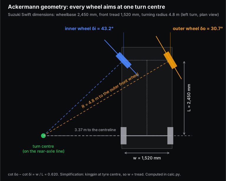
The derivation takes three lines. Put the turn centre O on the rear-axle line, a distance from the car's centreline. The inner pivot is from O sideways and ahead of it. The outer pivot is sideways and ahead. Each wheel's axle must point at O, so:
Subtracting the first from the second removes :
Two points matter in exams and in design reviews. First, is the distance between the steering axes (kingpins), not the track width. Track is measured between tyre centres and is usually larger. Second, the result is purely geometric. Ackermann steering is a kinematic condition, valid when the tyres are not generating slip angles: at parking and walking speeds. The section on anti-Ackermann below covers what changes at speed. In many Indian university syllabi the same equation appears as the "fundamental equation of correct steering", , with the pivot spacing and the wheelbase.
Worked example: Ackermann angles for a Suzuki Swift
Suzuki's specification sheet for the current Swift lists a 2,450 mm wheelbase, a 1,520 mm front tread (1,530 mm on one variant) and a 4.8 m minimum turning radius, with electric power-assisted rack-and-pinion steering. Kingpin spacing is not published. To keep the example clean, we place the steering pivot at the tyre centre, so mm. We also treat the 4.8 m radius as the path of the outer front wheel. Both are simplifications; real kingpins sit slightly inboard.
Step 1: the geometry ratio.
Step 2: the outer wheel at full lock. The outer front wheel runs on the 4.8 m circle. Its distance from the turn centre is the hypotenuse of a triangle whose side along the car is the wheelbase:
Step 3: the inner wheel from the Ackermann condition.
Step 4: where the turn centre is. mm from the centreline. The four wheels then trace circles of about 4.80 m (outer front), 3.58 m (inner front), 4.13 m (outer rear) and 2.61 m (inner rear).
Result: at full lock the inner wheel needs about 43.2° and the outer about 30.7°, a 12.5° difference. Near straight ahead the difference is tiny: at a 5° inner angle the ideal outer angle is 4.74°, only 0.26° less. At 20° inner, the outer should be 16.54°, 3.46° less. Ackermann matters most when the wheel is near full lock: parking, U-turns and tight ramps.
To try other cars, enter the wheelbase, kingpin spacing and rack geometry in Skill-Lync's free Ackermann steering geometry calculator. It also estimates turning circle and parking effort.
How does the Ackermann steering mechanism work?
The classic Ackermann steering gear is a four-bar linkage shaped like a trapezoid. The fixed link is the front axle between the two kingpins. The two short links are the steering arms, one bolted to each stub axle. The long coupler is the tie rod. Because the arms are angled inward, the inner wheel turns through a larger angle than the outer.
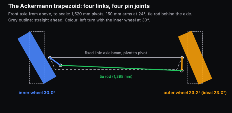
Here is why the angled arms create the difference. Straight ahead, each arm leans inward at an angle to the car's centreline. When you steer left, the tie rod moves sideways. The left (inner) arm swings toward a more sideways position, so its end moves less and less along the tie rod's line. Each millimetre of tie-rod travel therefore turns it further. The right (outer) arm swings toward a more fore-aft position, so its end moves more directly along the tie rod, and the same travel turns it less. The result is more angle on the inside wheel, which is what Ackermann asks for.
Textbook theory of machines notes (for example, Rama University's lecture notes on steering gear) describe the Ackermann gear as having only turning pairs (pin joints). They state that it satisfies the correct-steering condition exactly in only three positions: straight ahead, and one position each when steering left and right. Everywhere else it is a close approximation. That is the trade-off: the mechanism is simple and durable, but not exact.
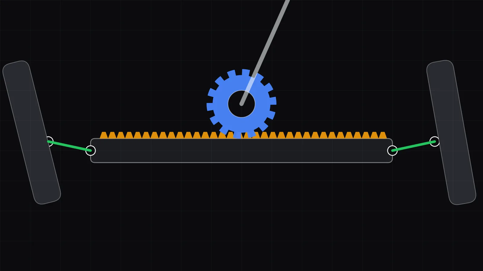
A modern car does the same job with a rack-and-pinion gear. The steering wheel turns a pinion that slides a rack sideways. Two tie rods connect the rack ends to the steering arms. The Ackermann effect still comes from the steering-arm angle and the position of the tie-rod joints. The gear itself converts the driver's rotation into rack travel. For the gearbox types and steering ratio, see our guide to steering gearbox mechanisms.
What is percentage Ackermann, and how close does a real linkage get?
Percentage Ackermann compares the toe-out a linkage actually produces with the toe-out ideal Ackermann needs at the same inner-wheel angle. 100% means perfect geometry at that angle, 0% means parallel steer, and above 100% means the outer wheel turns too little. Because it changes across the steering lock, always state the inner angle with it.
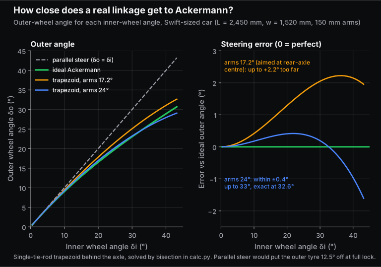
A common rule of thumb says to aim the steering arms at the centre of the rear axle. For our Swift-sized car that means , or . That proportion is exact for the Davis gear (next section). When we solved the four-bar trapezoid exactly, though, it under-delivered. It gave about 55% Ackermann at a 5° inner angle and 84% at full lock, with the outer wheel steered up to 2.2° too far.
The reason shows up in a small-angle expansion. For a single tie rod behind the axle, percentage Ackermann near straight ahead works out to:
Here is the steering-arm length. The numeric solution agrees with this to within 0.1 percentage point. It gives 53% for and 78% for . Steeper 24° arms keep the error within ±0.4° up to a 33° inner angle. They are exact at 32.6° and over-correct beyond that (113% at full lock).
The practical lesson for design: check the geometry by computing it, or by sketching the linkage at three or four angles. Don't assume a rule of thumb is accurate. This is exactly what multibody tools like Adams/Car and MotionView automate.
Ackermann vs Davis steering gear: what is the difference?
Both mechanisms aim to satisfy the same correct-steering condition. The Davis gear does it exactly at every angle, but uses sliding pairs that wear and lose accuracy. The Ackermann gear uses only pin joints, so it is simpler and lasts longer, but it is exact in only three positions. That is why road vehicles use Ackermann-type linkages.
| Ackermann steering gear | Davis steering gear | |
|---|---|---|
| Kinematic pairs | Turning pairs only (four pin joints) | Sliding pairs (slotted links and a sliding cross rod) |
| Accuracy | Exact in three positions: straight, one left, one right | Exact at every steering angle (in theory) |
| Where it sits | Behind the front wheels | In front of the front wheels |
| Wear | Low: pin joints, easy to lubricate and seal | High: sliding members wear and the gear becomes inaccurate |
| Design relation | Arm angle and arm/tie-rod lengths chosen so the error is small across the lock | (pivot spacing over twice the wheelbase) |
| Use | Cars, trucks, buses (as the steering-arm geometry with a rack or a steering box) | Mostly a textbook mechanism |
A typical exam problem: a Davis gear has 1.2 m between the front pivots and a 2.7 m wheelbase. Find the inclination of the track arms.
For the Swift dimensions, the same formula gives 17.2°. That is the arm angle of the rear-axle-centre rule of thumb above. It is exact for the Davis gear, but only approximate for a pin-jointed trapezoid.
Ackermann, parallel or anti-Ackermann: which do real cars use?
Road cars use geometry that approximates Ackermann, but not pure Ackermann, because the simple rule ignores tyre slip and compliance. At speed every tyre runs at a slip angle, and the inner and outer front tyres need different slip angles. Some racing cars therefore use reverse (anti-) Ackermann, trading low-speed behaviour for fast-corner performance.
Three regimes are worth knowing:
- Ackermann (close to 100%): best for parking, tight turns and low speeds, where tyres roll with little slip. As the linkage chart above shows, a real linkage only stays close to 100% over part of the lock; the designer chooses where.
- Parallel steer (0%): both wheels turn by the same angle. It is simpler, and at high lateral acceleration the inner tyre's lower load makes the error matter less. At full lock on our example car, though, the outer tyre would be 12.5° off its path.
- Anti-Ackermann (below 0%): the outer wheel turns more than the inner. Some racing cars use it to compensate for the large difference in slip angle between the inner and outer front tyres in fast corners, which can also lower tyre temperatures. The price is poorer behaviour in slow corners.
Modern road cars also add compliance effects that the simple formula ignores: bushes deflect, and toe changes as the suspension moves. That is why steering geometry is tuned in multibody simulation and on test tracks, not set from the formula alone.
Where is Ackermann steering used?
Ackermann geometry, exact or approximate, is used on wheeled vehicles that steer by turning their front wheels: passenger cars, SUVs, commercial vehicles and student-built race cars. It also underlies the kinematic "car model" used for car-like robots and autonomous-driving software, which links the steering angle to the curvature of the path.
- Passenger cars with rack-and-pinion steering: the Swift in our example uses electric power-assisted rack and pinion. A pinion on the steering column slides a rack sideways, and two tie rods carry that motion to the steering arms. The arm angles and joint positions set the toe-out between the wheels.
- The classic single-tie-rod trapezoid: the four-bar gear of the theory of machines syllabus, with one tie rod joining two steering arms behind the axle, as in our linkage figure.
- Car-like robots and autonomous-driving software: in the Ackermann kinematic model, the heading rate equals speed times . For a given wheelbase, the maximum steering angle therefore limits how tight a path the vehicle can follow. Unlike a differential-drive robot, a car-like robot cannot turn on the spot.
- Student race-car and go-kart design: the percentage of Ackermann is a deliberate design choice, made with the tradeoffs in the previous section.
Advantages and limitations of Ackermann steering
| Advantages | Limitations |
|---|---|
| Tyres roll without sideways scrub in low-speed turns: less wear and squeal | A pin-jointed linkage is exact only at a few angles; elsewhere it is an approximation |
| Lower steering effort when parking, because no tyre is dragged | Ignores tyre slip angles, so it is not optimal at high lateral acceleration |
| Simple, durable four-bar linkage of pin joints | Large toe-out at full lock costs packaging space for the inner wheel |
| Predictable geometry that is easy to check by calculation | Bump steer and compliance change the real toe angles on the road |
How do engineers design and check steering geometry today?
A quick script like ours is the first check. After that, steering geometry is modelled in multibody dynamics software such as MSC Adams/Car or Altair MotionView, the tools used in Skill-Lync's suspension and multibody courses. There, the steering and suspension hard points (joint locations) are moved and the toe angles, percentage Ackermann, bump steer and turning circle are read off across the steering and suspension travel.
If you want to do this work as a chassis or vehicle dynamics engineer, Skill-Lync's Vehicle Dynamics using MATLAB course covers steering kinematics, tyre models and handling. Suspension Design using ADAMS covers building and tuning a suspension-and-steering model in Adams/Car. The vehicle dynamics course comparison lists all six related courses with hours and projects. If you are unsure which fits your background, talk to a Skill-Lync counsellor.
Frequently asked questions
What is the formula for Ackermann steering?
The Ackermann condition is . Here and are the outer and inner front-wheel angles, is the distance between the kingpins and is the wheelbase. If it holds, both front-wheel axes meet the rear-axle line at one point, so no tyre slides sideways in a slow turn.
Why does the inner wheel turn more than the outer wheel?
In a turn, the inner front wheel is closer to the turn centre, so it travels on a smaller circle. To stay tangent to that tighter circle, its heading must swing round further. For a car with a 2,450 mm wheelbase and a 4.8 m turning radius, that means about 43° for the inner wheel and 31° for the outer.
Is Ackermann steering used in modern cars?
Yes, as a starting point. Modern cars use rack-and-pinion steering with the steering arms angled to give near-Ackermann toe-out at low speed. They rarely use exactly 100%. Tyre slip angles at speed, compliance in bushes and packaging limits at full lock lead engineers to tune the percentage, and some racing cars use anti-Ackermann instead.
What is the difference between Ackermann and Davis steering gear?
Both aim to satisfy the correct-steering condition. The Davis gear meets it exactly at all angles, but uses sliding pairs that wear, sits in front of the wheels and loses accuracy over time. The Ackermann gear uses only pin joints, sits behind the wheels and is exact in three positions, so it is the one used on vehicles.
Who invented Ackermann steering?
Georg Lankensperger, a carriage builder in Munich, invented the geometry in 1816. His agent in England, Rudolph Ackermann, patented it in 1818 for horse-drawn carriages, which is why it carries Ackermann's name. Erasmus Darwin may have described a similar idea as early as 1758.
What is anti-Ackermann steering?
Anti-Ackermann (reverse Ackermann) is geometry in which the outer front wheel turns more than the inner one. It suits high-speed cornering. There, the heavily loaded outer tyre needs a larger slip angle to give its best grip. It makes low-speed turns worse, so it is mainly a race-car choice.
Sources and further reading
- Wikipedia, Ackermann steering geometry (history: Lankensperger 1816, Ackermann patent 1818, Darwin 1758; modern cars and reverse Ackermann; accessed 16 Nov 2026)
- Suzuki New Zealand, Swift specifications (wheelbase 2,450 mm, front tread 1,520/1,530 mm, minimum turning radius 4.8 m, electric power-assisted rack and pinion; accessed 16 Nov 2026)
- Rama University, Faculty of Engineering and Technology, Theory of Machines-I, Lecture 14: Steering gear mechanism, Davis steering gear and Lecture 15: Ackermann steering gear (accessed 16 Nov 2026)
- R. Eisele, RAW Book, Introduction to Ackermann Steering (derivation of the cotangent condition; 28 Nov 2017; accessed 16 Nov 2026)
- Wikipedia, Rack and pinion (rack-and-pinion steering; accessed 16 Nov 2026)
- Skill-Lync, Ackermann steering geometry and parking effort calculator
- Skill-Lync, Types of steering gearbox mechanisms