Wiring harness routing & packaging Rules Week 3 Challenge
AIM:
Q1. Download following cad data & define it as Electrical support using Electrical Part design Workbench. Define all the necessary properties.
P clamp
Q2. Download following Back shell cad data & define it as Electrical back shell using Electrical Part design Workbench. Define all the necessary properties.
Tyco 1738312-1 https://www.te.com/usa-en/product-1738312-1.html
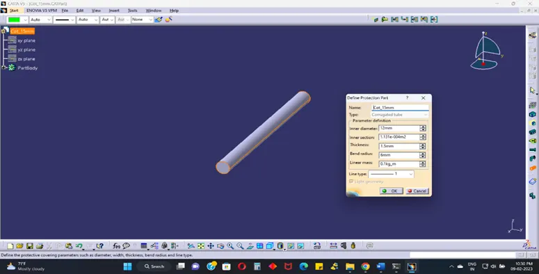
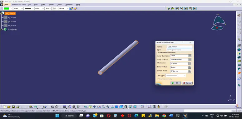
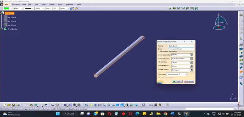
Q3. Create Following Corrugated tubes & add them in Catalogue under “Slit COT” family.
|
Name |
ID (mm) |
OD (mm) |
Thickness (mm) |
|
15mm COT |
12 |
15 |
1.5 |
|
20mm COT |
17 |
20 |
1.5 |
|
35mm COT |
32 |
35 |
1.5 |
|
10mm COT |
7 |
10 |
1.5 |
|
5mm COT |
3 |
5 |
1 |
Q1. Download following cad data & define it as Electrical support using Electrical Part design Workbench. Define all the necessary properties.
P clamp
Solution:
P clamp
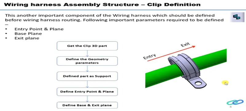
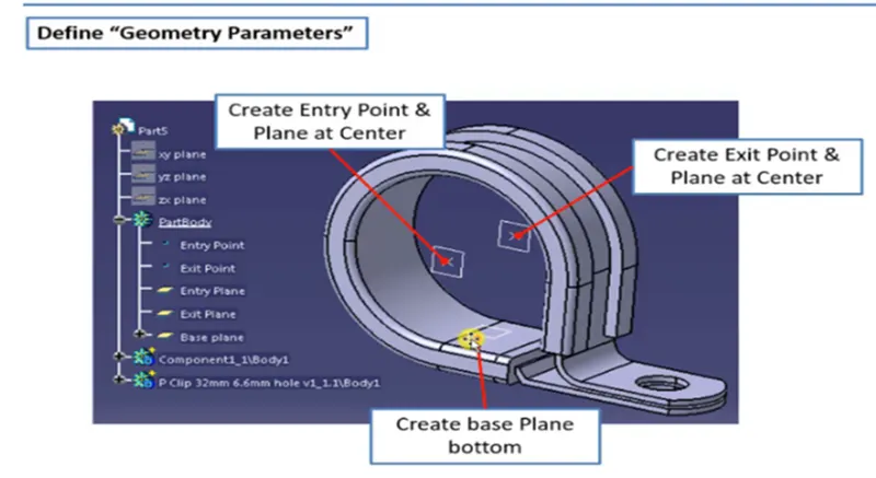
Operation:
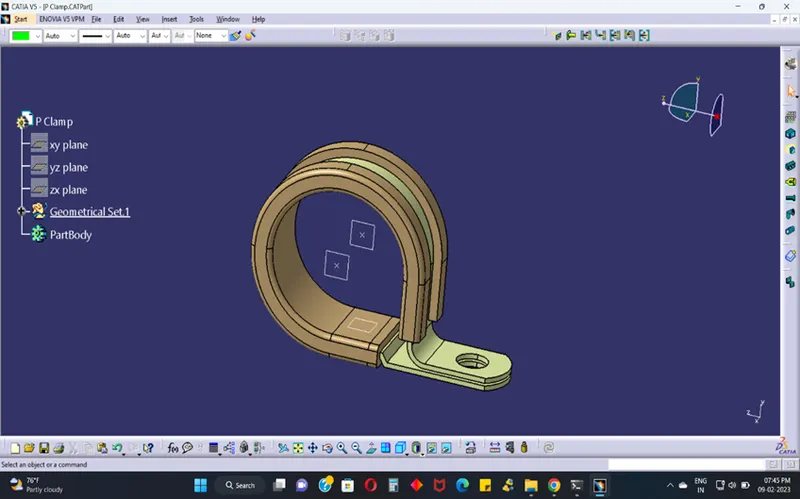
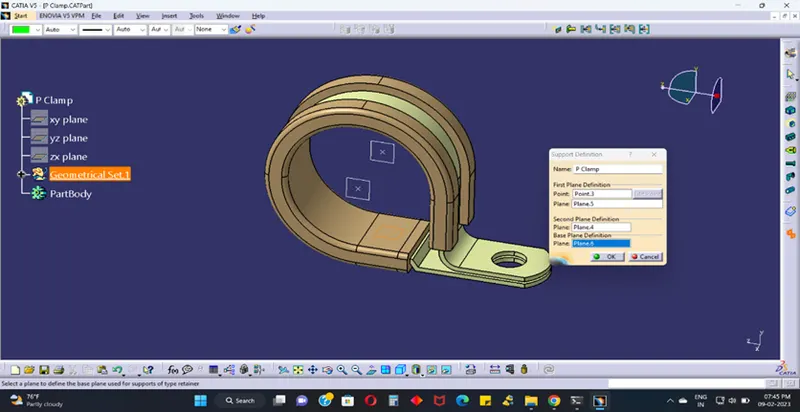
- To open on electrical part design and open it the file of P CLAM.
- There is two entry points & plane at centre, two exit points & plane at centre and base refer to create base plane bottom surface.
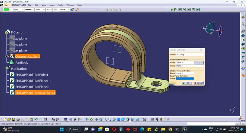
- To selected support definition tool and open it one dialogues first plane definition to select on entry point & plane, second plane definition to select on exit plane and base plane definition to select on base plane.
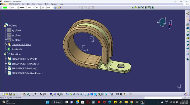
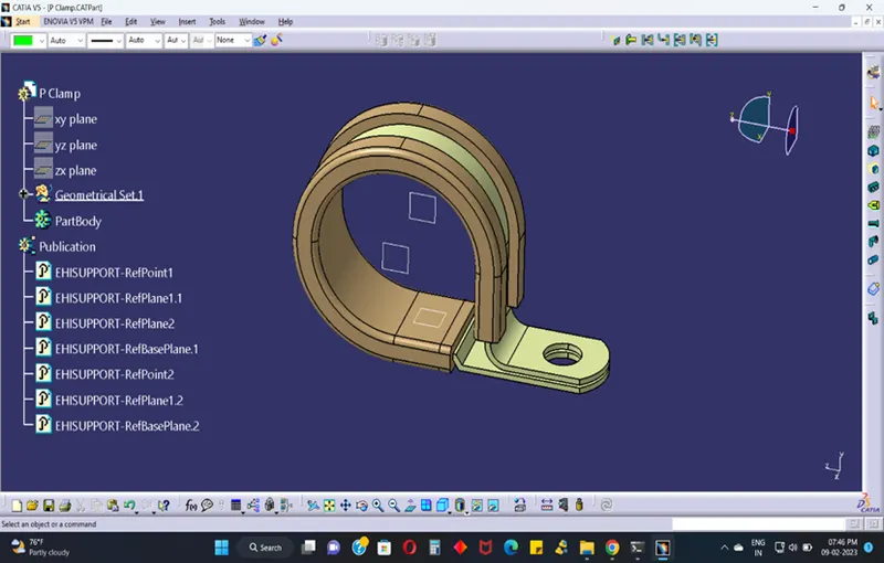
- To check it on publication and again to selected support definition tool refer to entry side on point & plane, exit side refer on plane, base surface to base plane to refer. To save the file.
Q2. Download following Back shell cad data & define it as Electrical back shell using Electrical Part design Workbench. Define all the necessary properties.
Tyco 1738312-1 https://www.te.com/usa-en/product-1738312-1.html
Process:
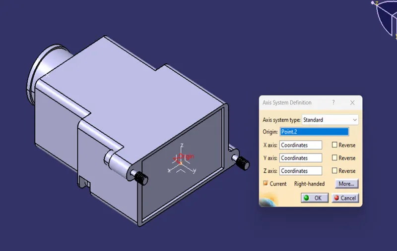
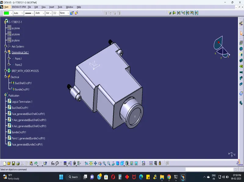
First specify the shell fixing point and the bundle entering point. Ensure that you also add the axis system to the fixing point.
The axis is in same direction as of connectors.
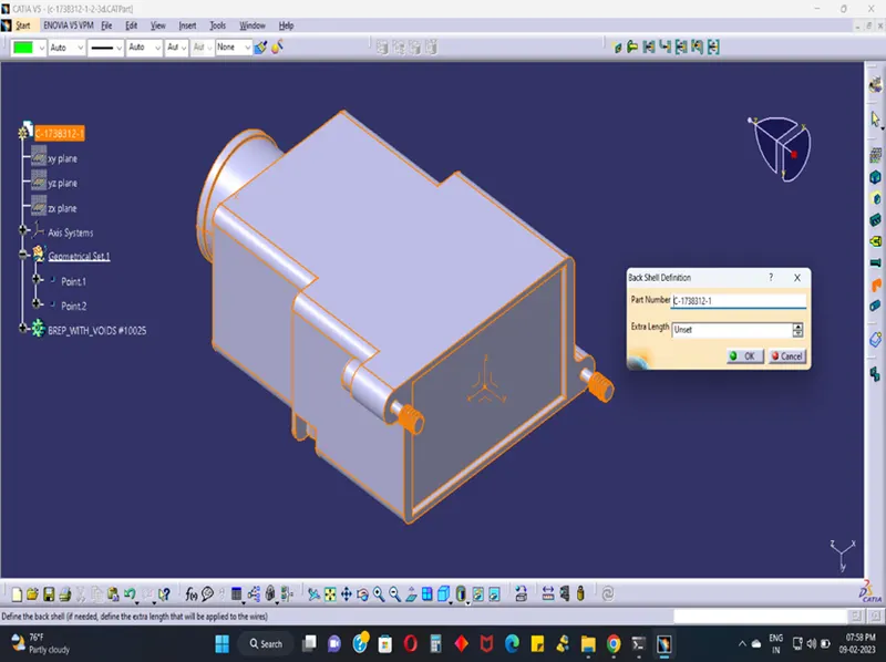
Definition back shell:
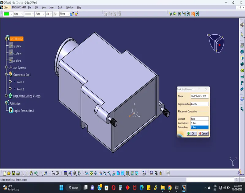
Definition back shell connection point:
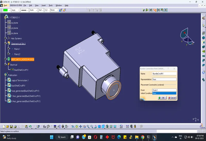
Bundle point connection definition:
Q3. Create Following Corrugated tubes & add them in Catalogue under “Slit COT” family.
|
Name |
ID (mm) |
OD (mm) |
Thickness (mm) |
|
15mm COT |
12 |
15 |
1.5 |
|
20mm COT |
17 |
20 |
1.5 |
|
35mm COT |
32 |
35 |
1.5 |
|
10mm COT |
7 |
10 |
1.5 |
|
5mm COT |
3 |
5 |
1 |
Process:
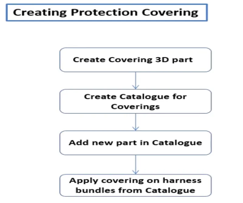
- To open on Electrical Part Design Model.
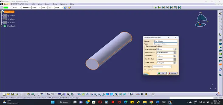
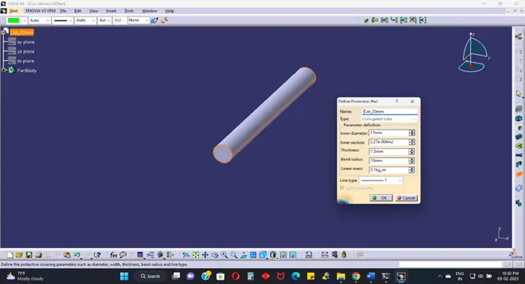
- Using Define Protection Part
- Select the type as Corrugated Tube
- Give the Required Parameters (Inner diameter, Thickness, Bend Radii (multiple thickness 1.5 times to outer diameter))
- Click on OK
- After giving the necessary properties save the file.
Cot 35mm:
Cot 20mm:
Cot 15mm:
Cot 10mm:
Cot 5mm:
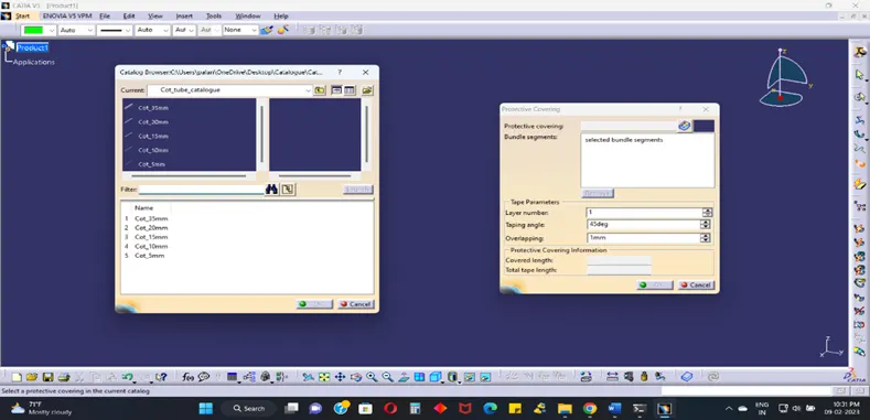
PROTECTIVE COVERING (Add Catalogues):