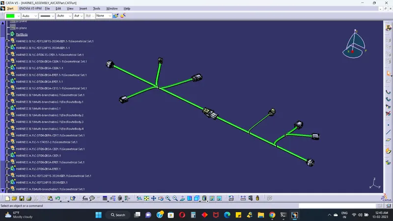
Wiring harness design in CATIA V5 - 3D modeling Week 5 & 6 Challenge
AIM:
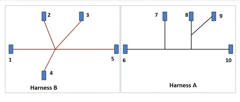
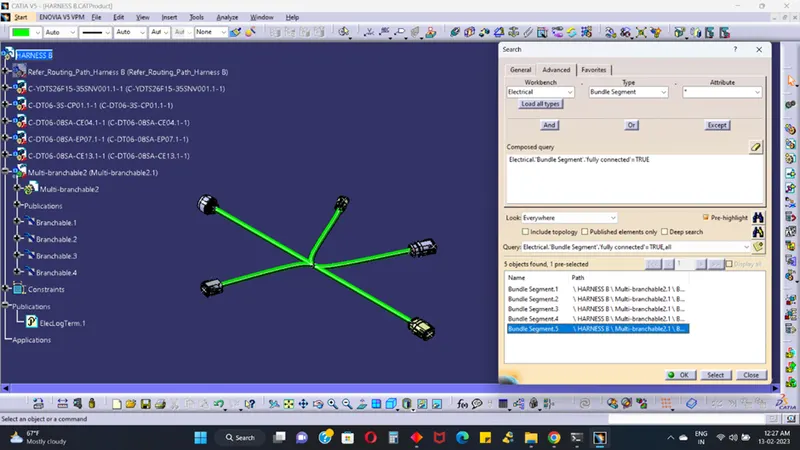
Q1. Route the following harness layout in Electrical workbench. Make assumption for harness bundle diameters. Use the connectors provided. After completion of routing,
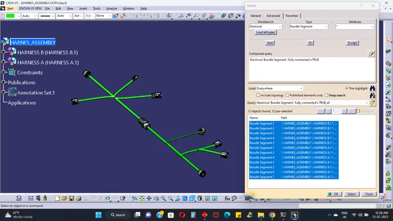
- Check the bundle Continuity. Add snap of result in submission
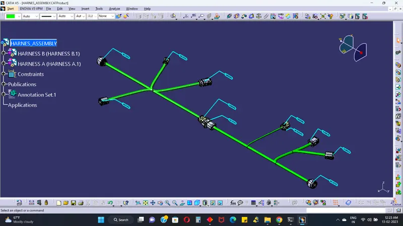
- Add annotation to all connectors. Make an assumption for annotations like connect 1, 2 etc
- Check for the bundle warning. Add snap.
- Generate CAT.Part of harness assembly and convert is in. IGS format.
Click here for CAD data and routing mapping data
Process:
Bundle connection point:
To open the part design and create the midpoint on bundle connection wire.
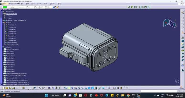
Connector connection point:
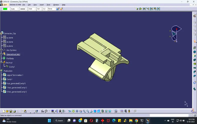
To create the midpoint on connector connection face and Axis system to refer the connector connection point create and change axis direction connector connection face to same direction on Y-axis mounting direction, change direction on X-axis on locking mechanism and X-axis perpendicular to the Z-axis.
Switch to Electric Part Design:
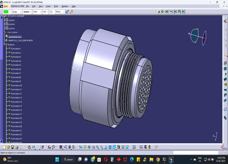
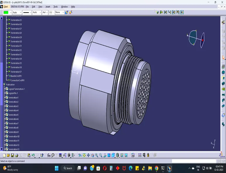
To select the define part as connector tool, to choose on single insert connector and give no. of termination as 4 because we have 4 entry points for wire.
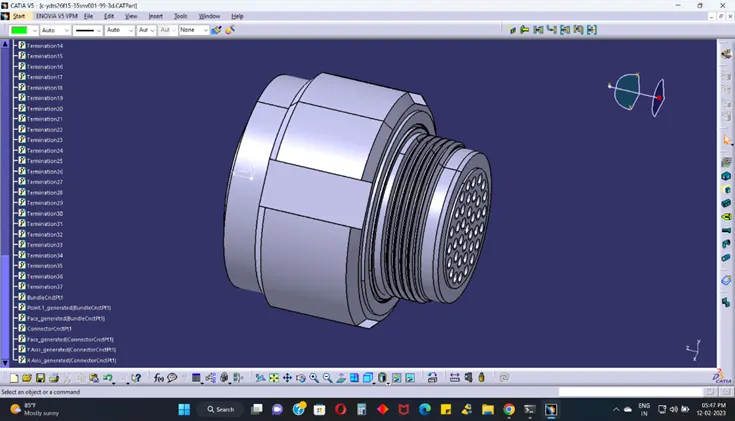
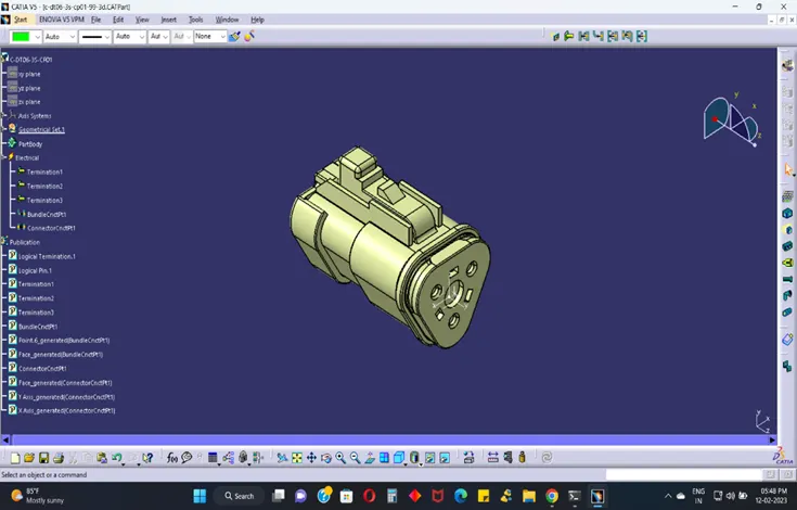
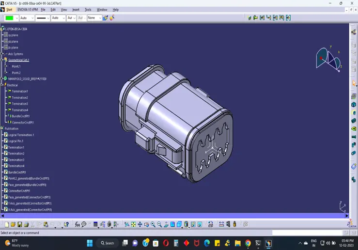
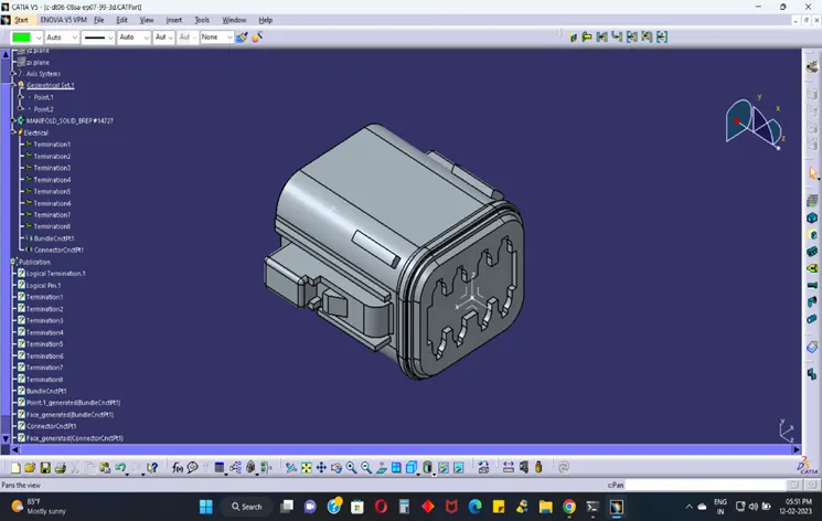
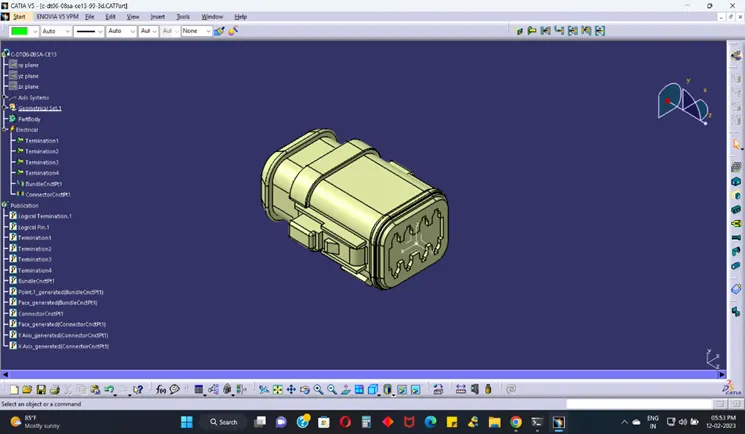
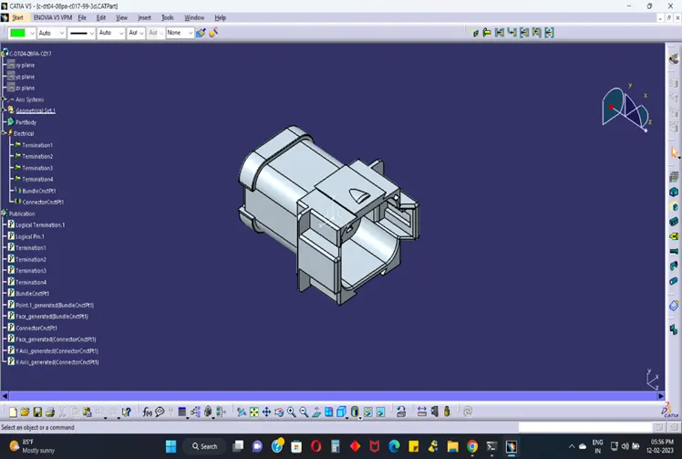
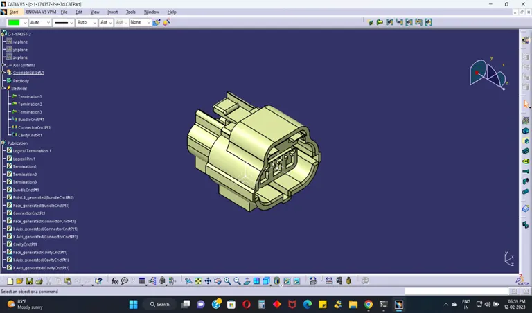
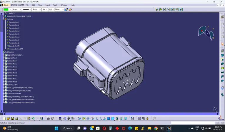
HARNESS B:
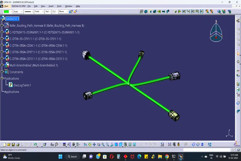
After all the connectors are defined, the workbench was switched to Electrical Harness Assembly where Geometrical Bundle was activated. All the connectors were routed using the multi-Branch able Document command.
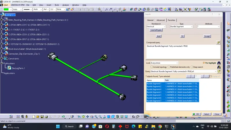
CONNECTIVITY CHECK:
HARNESS A:
After all the connectors are defined, the workbench was switched to Electrical Harness Assembly where Geometrical Bundle was activated. All the connectors were routed using the multi-Branch able Document command.
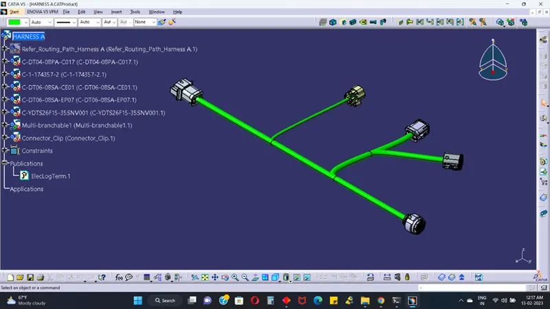
CONNECTIVITY CHECK:
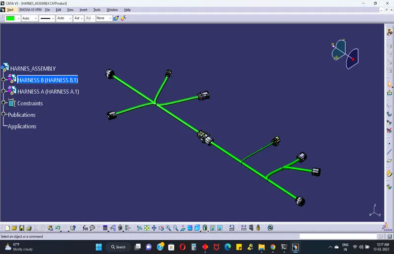
HARNESS ASSEMBLY:
Assembly on harness A and harness B combine to single connection process.
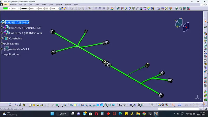
CONNECTIVITY CHECK:
ANNOTATIONS:
TO CONVERT GENERATE CAT.PART FROM PRODUCT: