Project 2
Aim:
Route the Wiring Harness on given Car body and prepare flatten view drawing in Catia V5
Objective:
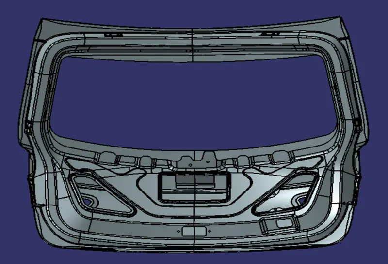
The objective of this project is to route the wiring harness and prepare flatten view drawing for the tailgate of the car. All types of packaging rules have to be considered while routing the harness and industry-based practices shall be demonstrated in harness design. All necessary details like clearance, clipping/clamping selection, harness fixing requirements, harness continuity should be provided in order to design the wiring harness.
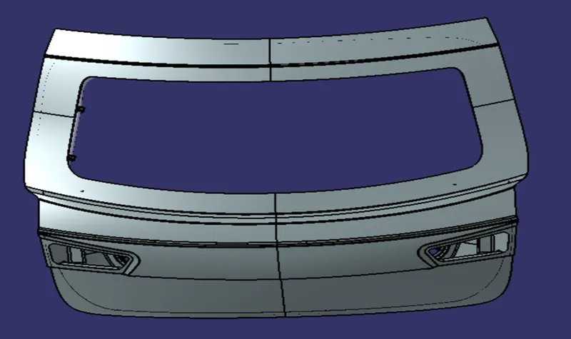
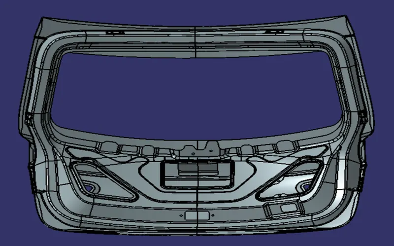
The design of the harness comprising of the interconnected mesh of wires is crucial. Select the important components like connectors, fuses, and sensors. Ensure their reliability.
Study the schematic circuit diagram. Divide the entire vehicle into detachable parts like chassis, body, and engine. Then design the wiring harness that suits the requirements. Ensure that it fits the customer requirements, shape, and size of the vehicle. Chalk out electrical routing in a way that reduces complexity and uses minimal space.
There are three types of engine wire harnesses based on the vehicle part you are looking at. The engine wire harness is a set of wires, connectors, and terminals to relay the signal to and from the engine. It also communicates messages from all sensors within the engine.
The body wiring harness routes electrical and electronic bits of information. It’s what keeps the major components of the automobile working. The body wiring takes care of power windows, lighting, and other accessories. And then, you need a chassis wiring harness for connecting the components.
Assumptions:
- Wiring harness should be routed in such way that it is easy to assemble and access.
- Avoid harness routing and clipping in the blind zones or hard to reach areas during harness assembly or service.
- Provide additional slack if needed according to the surrounding and harness bending requirement. If harness is passing through the closures/doors or tail gates then envelope dimensions during opening and closing of doors shall be considered to provide the slack. Check the harness slack requirements with open and close conditions to avoid excess slack.
- Easy manufacturing, installation, removal and maintenance have to be considered while designing the wire harness.
- Routing through small structural holes and openings shall be avoided. To minimize chaffing and handling of the wiring harness during installation.
- To avoid the harness routing and clipping in blind zones of the operator during the assembly and the service.
- To avoid sharp edges on the sheet metal parts and if it is not possible then provide protection parts to prevent damage of the wire bundle.
- The bend ratio for all the bundle segment is considered to be 1.4
- To limit the number of branches from a single branch point to 4.
- Minimum distance between clip and nearest branching point should be 25mm.
- Fir tree clips and other clips can be added to the Geometric bundle as they are electrically defined and are part of the Wire harness routing and should be provided with the Wire bundle package.
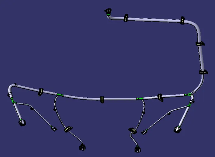
Procedure:
Create context assembly product file BACK DOOR
Define the connectors electrically
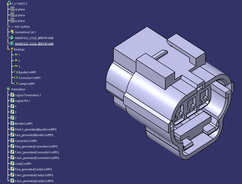
C-2-174357-2:
Bundle connection point:
To open the part design and create the midpoint on bundle connection wire.
Connector connection point:
To create the midpoint on connector connection face and Axis system to refer the connector connection point create and change axis direction connector connection face to same direction on Y-axis mounting direction, change direction on X-axis on locking mechanism and X-axis perpendicular to the Z-axis.
Switch to Electric Part Design:
To select the define part as connector tool, to choose on single insert connector and give no. of termination as 4 because we have 4 entry points for wire.
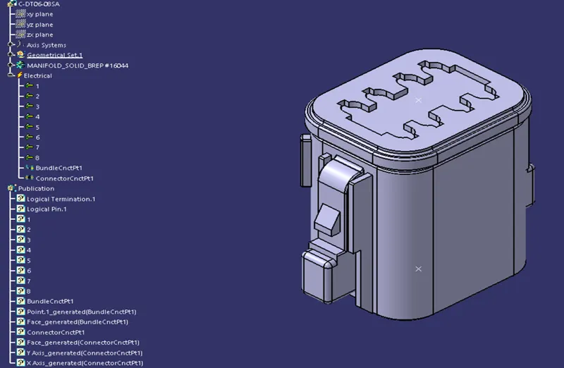
C-DT06-08SA:
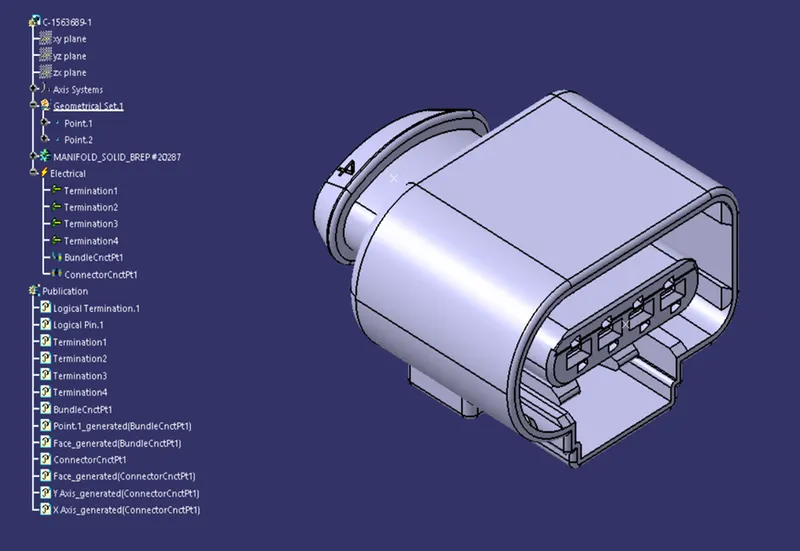
C-1563689-1:
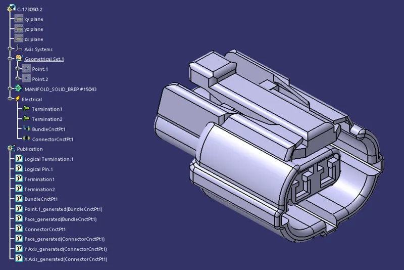
C-173090-2:
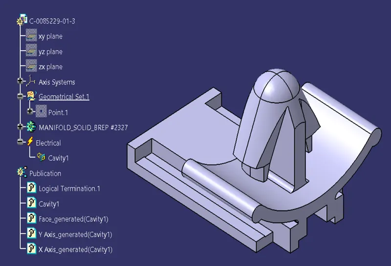
C-0085229-01:
P-Clamp:
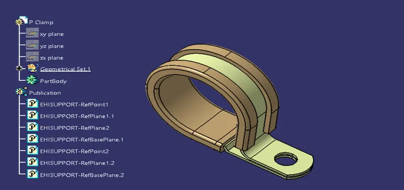
- To open on electrical part design and open it the file of P CLAMP.
- There is two entry points & plane at centre, two exit points & plane at centre and base refer to create base plane bottom surface.
- To selected support definition tool and open it one dialogues first plane definition to select on entry point & plane, second plane definition to select on exit plane and base plane definition to select on base plane.
- To check it on publication and again to selected support definition tool refer to entry side on point & plane, exit side refer on plane, base surface to base plane to refer. To save the file.
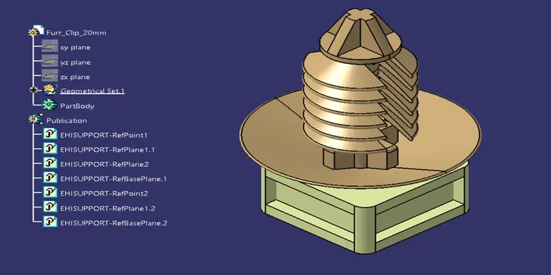
FURR TREE CLIP:
Adding sheet metal bracket:
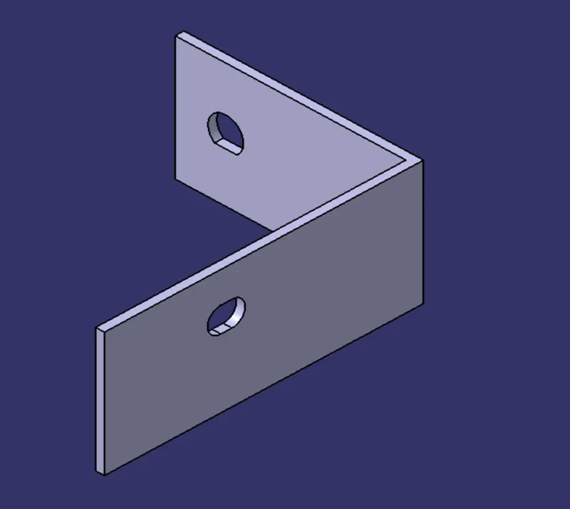
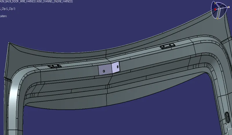
Now, we have to add sheet metal bracket in order to provide mounting for the interconnection connector. Also, we have to make sure that the bracket is placed inside the context assembly and outside of engine and geometrical bundle assembly. The bracket should be mounted on the existing bolt as shown below. This bracket should have locked system in clockwise direction so that it can't be move freely. Herein below figure, rib is performing the locking feature for the bracket. All the design ideas should be discussed with the engine designing team so that there won't be any disturbance for the smooth working of engine in real world application. Now, we have to mount that electrically connected interconnection connector and cavity on sheet metal bracket as shown in above figure. We have to mount 9 P-clamps also on the existing bolts of the engine so before that we have to define P-clamp electrically with geometrical parameters, entry and exit point on both left and right side of the P-clamp as shown in below figure. Here, we have mounted 9 P-clamps on the existing bolts of the engine for the wire harness routing.
Adding connectors:
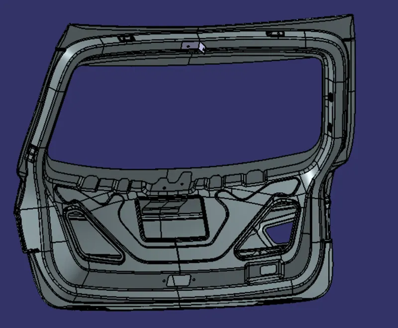
In this step, we are placing connectors. So, we will require total 07 connectors which have to be added in the Engine Harness Geometrical Bundle Assembly. We have to use manipulation tools along with compass, snap and smart move features to locate all the 07 connectors at their desired locations.
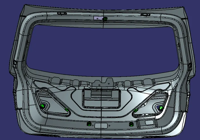
ADDING P-CLAMP:
To open on electrical part design and open it the file of P CLAMP. There is two entry points & plane at centre, two exit points & plane at centre and base refer to create base plane bottom surface. To selected support definition tool and open it one dialogues first plane definition to select on entry point & plane, second plane definition to select on exit plane and base plane definition to select on base plane. To check it on publication and again to selected support definition tool refer to entry side on point & plane, exit side refer on plane, base surface to base plane to refer. To save the file.
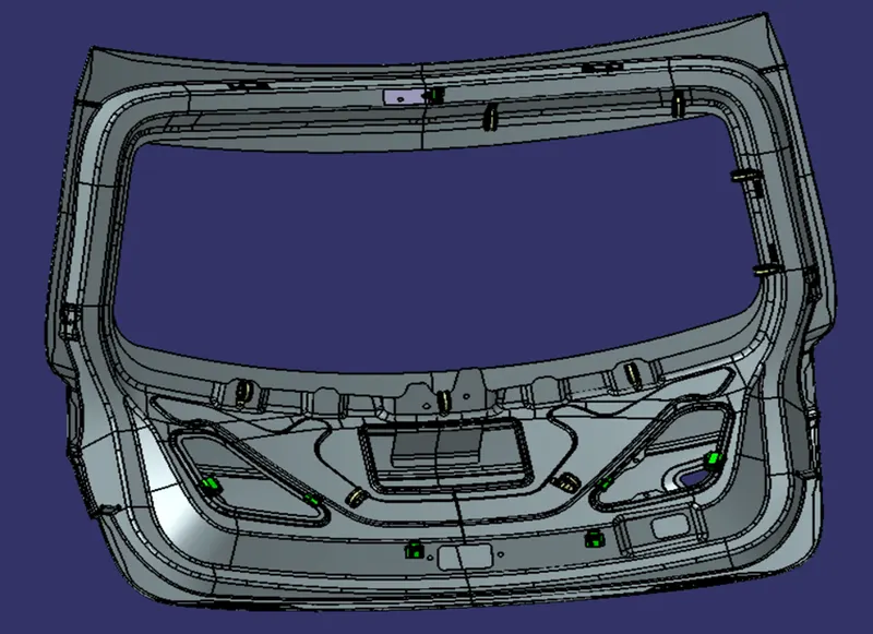
ADDING FURR TREE CLIP:
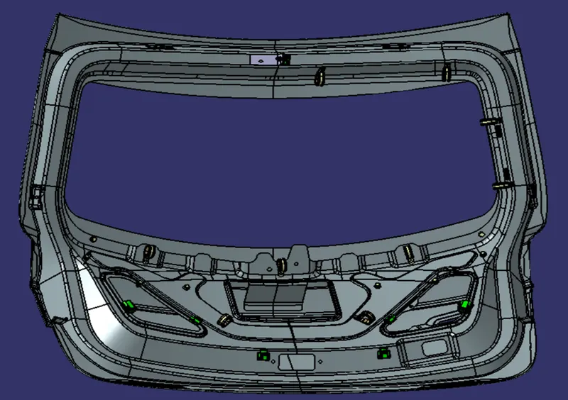
THE ELECTRICAL HARNESS:
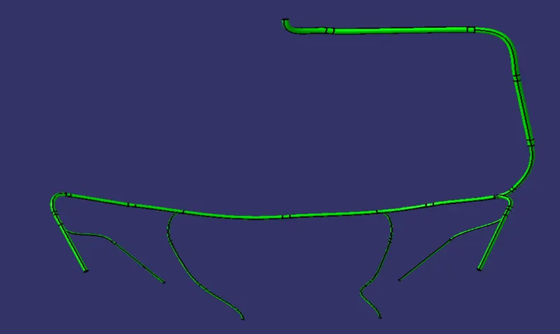
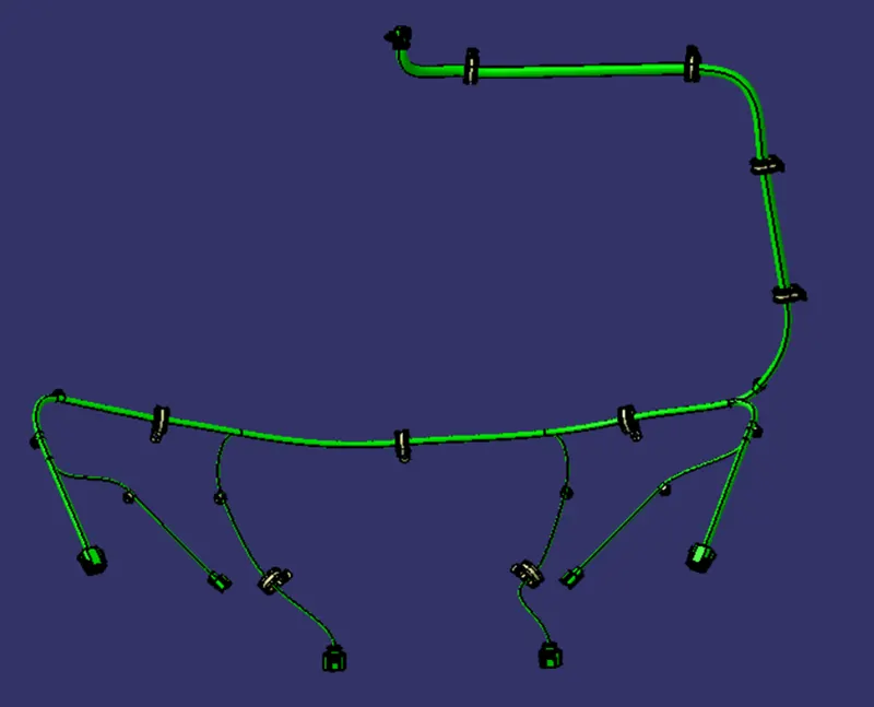
The connectors in the assembly should be electrically defined and it is placed in the appropriated position on the engine surface. After positioning the connectors place the supporting mounting clips in the engine to achieve the proper routing without fouling of the bundle with the surrounding parts. After achieving the route, the harness in the geometric bundle, make sure the bundle segment does not clash with the surrounding parts. Flatten the geometric bundle after finalised the geometric bundle, make sure for the bundle connectivity in the wiring harness.
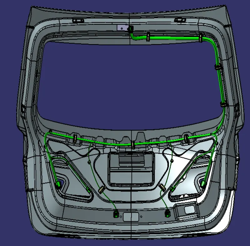
WIRE ROUTING
Checking bundle continuity:
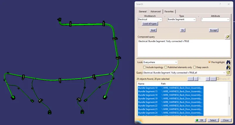
To check bundle connectivity, go to edit, select search option, go to advanced tab and select the workbench as electrical, type as bundle segment and attribute as fully connected and attribute criterion as true if, you want to check all connected bundle segments and false if you want to check all the unconnected bundle segments. The select result should be as TRUE or FALSE and the click search to see the connectivity analysis result.
After bundle routing, we have to add protective covering to the harness bundle so that it will get protected from the damage.
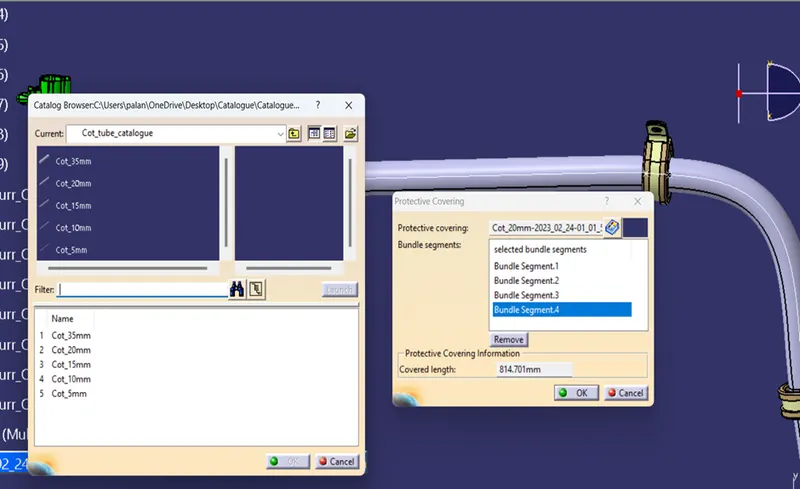
Adding Corrugated tube to the Catalogue:
Harness bundle should be protected with flexible rubber cover at the interconnection region where it is a critical place and subjected to opening and closing of door. There are more possibilities to damage the wiring harness if no proper protection covering is provided.
Corrugated conduits and protective hoses with various properties, from heat resistance through abrasion protection and impact strength to noise reduction, protect valuable cables against all unfavourable external influences.
Slit COT tubes are provided for protecting the harness from physical and other environmental damages that can occur in the long run.
Start or End Extremities at the Connector bundle entry side should be given a gap of 30mm.Selection of corrugated tubes are mainly driven by the wiring harness bundle diameter and temperature resistance requirements.
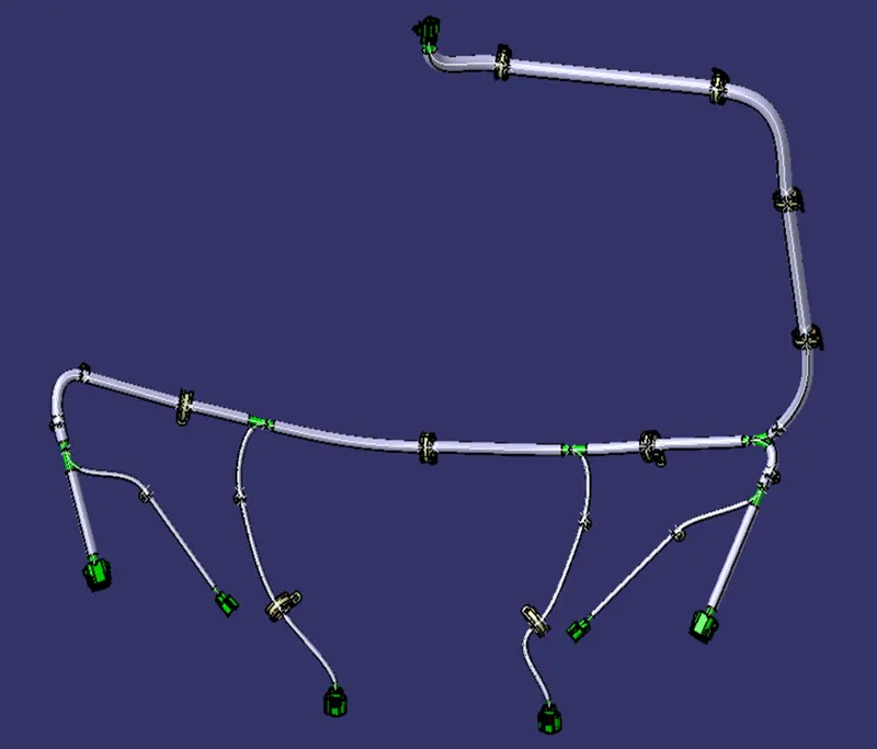
To create flatten view of the engine harness:
creating flatten view we have to work in Electrical Harness Flattening workbench of Catia V5. We should also make sure that the flattening file is saved in the same folder where other files of harness assembly are saved.
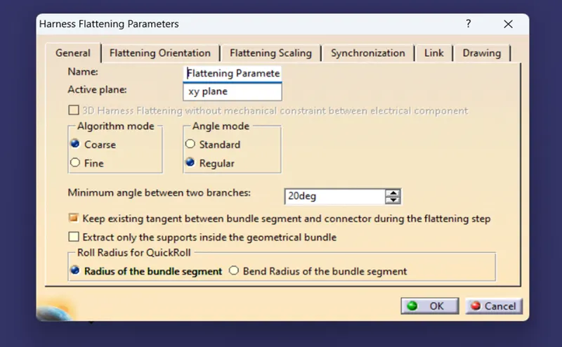
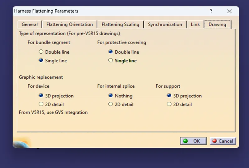
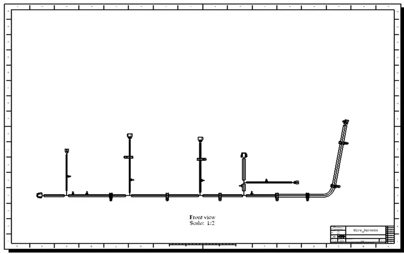
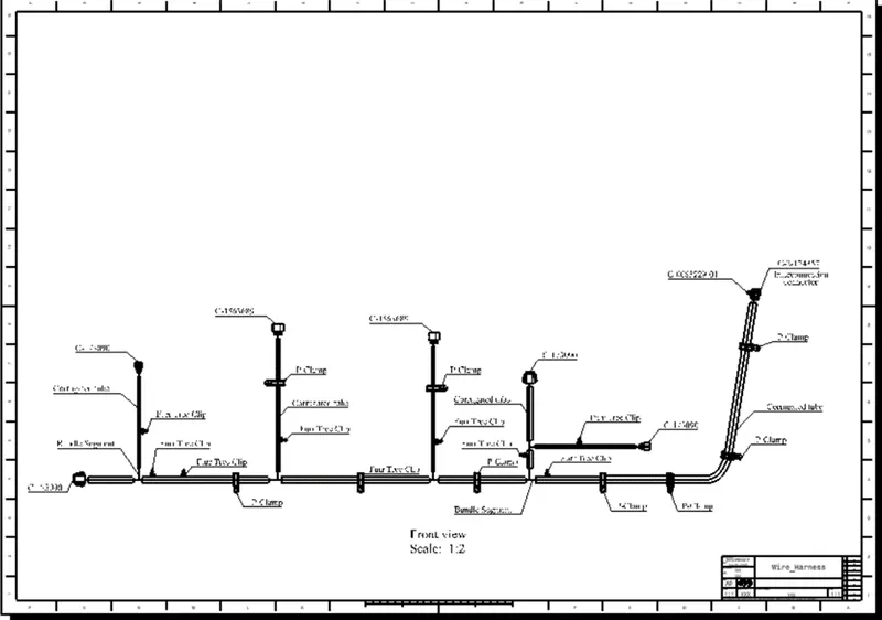
Before creating flatten view, first we have to define flattening parameters. Make sure that selecting 'Single line' for bundle segment and 'Double' line for protective covering. We have extracted the bundle assembly into Engine Harness Flattening Product file and then flattened the file along face of interconnection connector as shown in above figure. At this stage, for clarity, we have been hidden the flattening diagram of the plastic guiding channels from the drawing view.
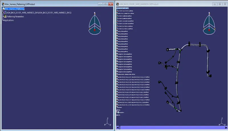
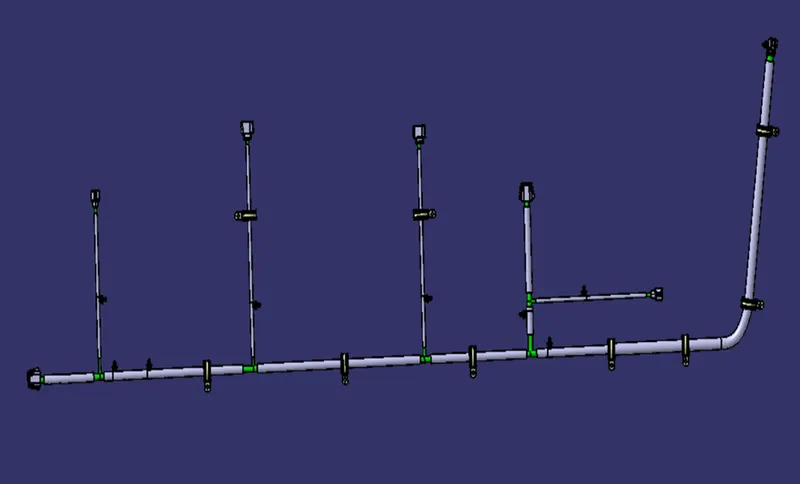
Create drawing of the flattened harness:
Go to new and select drawing to create a new drawing file. Select front view command, go to the flattened harness window and select a suitable face to create drafting of the harness. The wiring harness appears as shown below.