Week 9 - Project - Master Section Development
DESIGN AND DEVELOPMENT OF B-PILLAR THROUGH MASTER SECTION
OBJECTIVE
- Create the door applique Plastic component through the given Class-A surface, and create tooling axis, perform draft analysis and also create Class-B surface& Class-C surface.
- Create engineering features like locators and heat stakes.
INTRODUCTION
The Draft allows the part to easily eject from the mold. The draft angle is to reduce friction between the core, cavity and part and it also avoid the damages. The minimum draft angle is 0.5 degree and the most common draft angle used in the plastic design is 3 degrees.
In CATIA the draft analysis is performed based on colour ranges identifying zones on the analysed element where the deviation from the draft direction at any point, corresponds to specified values.
Tooling direction is the main element that to be consider while designing a plastic component. In moulding machine the arrangement is given to open the mould along the direction. It is the direction in which the core and cavity opens.
CLASS A SURFACE
1.Visible surface and aesthetic look
2.Surface with textures
3.Surfaces provided by customer(OEM)
4.Don't have any features like(rib ,snap ,bosses etc.) on class A surface.
5.Class A surface is made from scanned data with different software like alias etc..
6.Surfaces which is having CURVATURE CONTINUITY IS CALLED class-A.
CLASS B SURFACE
1.Invisible Surfaces.
2.Surface mostly don't have textures
3.Surface need to be create according to class-A surface.
4.Having all features(Rib, boss, snap etc.) in B-side surface only.
5.Surfaces which is having TANGENT CONTINUITY IS CALLED class-B
CLASS C SURFACE
Which join both Class-A and Class-B Surface
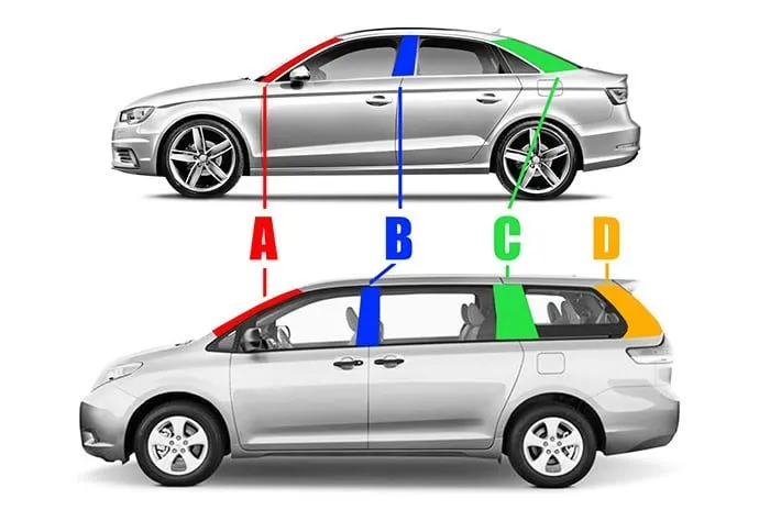
B PILLAR
B Pillar is the most complex component/structure of the vehicle body. This is because the front door closes on the B pillar while the rear door hinges onto it. The B pillar or the center pillar in vehicles is made of steel. It is welded to roof panel on top and the vehicle’s floor pan at the bottom. This pillar provides structural support to the vehicle’s roof.
Manufacturers skip the B pillar while naming other pillars. Hence, some vehicles do not have a B Pillar. The carmakers term those cars as 'Hardtops.' Instead, the vehicle specification shows the rearmost pillar as the C pillar. The manufacturers offer the Hardtops in nearly all four-door body styles. They include sedans, coupes, and wagons/MPVs. The cars without B pillars increase passenger’s visibility. However, they have limited structural support and strength. General Motors later started providing B pillars in Hardtops. Thus, it created a new vehicle body type and thereby broadened the definition of Hardtops.

DOG HOUSE
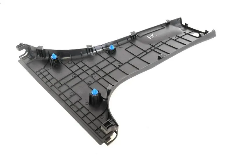
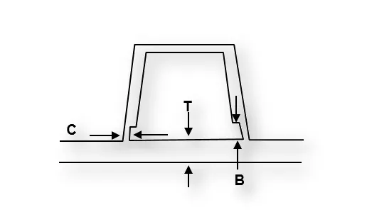
Dog house is an engineering feature used in plastic design. Dog houses are used as support feature. Dog houses are subjected to draft analysis to prevent breakage of the component during ejection from mould.
RIBS
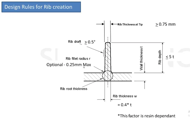
When the normal wall thickness is not stiff enough or strong enough to stand up to service conditions the part should be strengthened by adding ribs rather than making the whole wall thicker. The principle is the familiar one used in steel girders where 'I' and 'T' sections are almost as rigid as solid beams but are only a fraction of the weight and cost. Ribs are used to improve the rigidity of a plastics part without increasing the wall thickness so much that it becomes unsuitable for injection moulding. Ribs are important in the design of plastics parts because they allow us to make a component rigid without making it too thick.
Points to be considered while designing ribs
- The draft angle should be minimum 0.5° per side. Taper ribs for mould release.
- The rib thickness should be minimum 40% to maximum 75% of the wall thickness
- Rib depth should not be more than 5 times the rib thickness.
- Rib root thickness should not be more than 30% greater than the wall thickness.
- Fillet radius should 0.25mm maximum.
- Ribs should not be placed in the side walls.
- Unidirectional ribs should be spaced apart by at least 2 and preferably 3 or more times the nominal wall thickness.
LOCATING PINS
- These rib like structure on class B surface of plastic components which is used to position the child part with parent part while assembly.
- These locators are placed in the multiple location on the part depending upon the degree of freedom which needs to be arrested.
- They are classified into 4way and 2way locators depending upon their purpose and shape.
- Locators are used to locate a component to arrest its degree of freedom using 3-2-1 principle.
- The design rules for locating pins is same as Ribs
METHODOLOGY
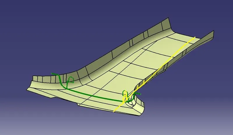
GIVEN CLASS – A SURFACE (DOOR APPLIQUE)
PROCEDURE
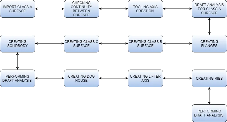
Continuity check:
- Input the class A surface
- After receiving the class A surface check the continuity of the given class a surface to ensure that there is no discontinuity in the class A surface. This can be checked using join or boundary option
TOOLING AXIS
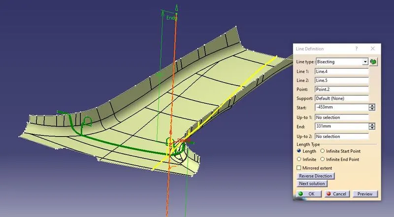
- Using master section 1 and 2 extract the edges.
- Create a point in between the lines.
- Two bisecting lines are created from opposite sides of the locator edges through the created point.
- Then a bisecting line is created using the above created two line
- The created line is the final tooling axis of the component
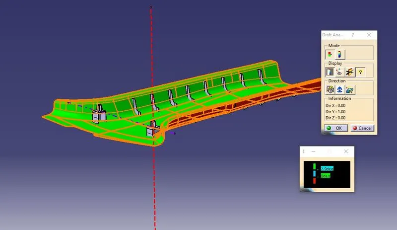
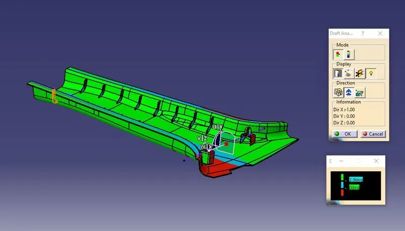
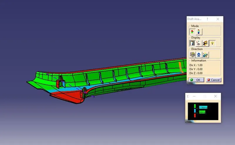
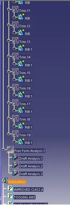
DRAFT ANALYSIS
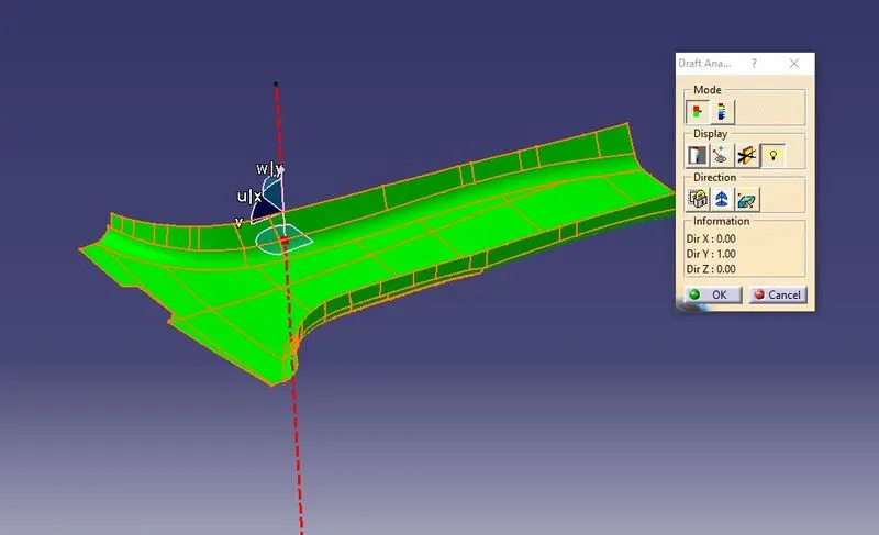
- For plastic parts the Nominal draft angle is 3deg, but even 7deg is allowed for the subassemblies like ribs and slots
- INSERT - ANALYSIS - FEATURE DRAFT ANALYSIS
- First the compass is moved to the part (the compass should be placed on the tooling axis) which used to define the new current draft direction, then lock the draft direction using the lock icon
- The colour chart indicates the various condition of the draft angle. the green colour indicates that the part passes and the and can be used for the further operations
- By using the analysis under the running point icon we can check draft angle at the various surfaces of the component
- There are two modes in the Draft analysis quick mode and fully detailed mode
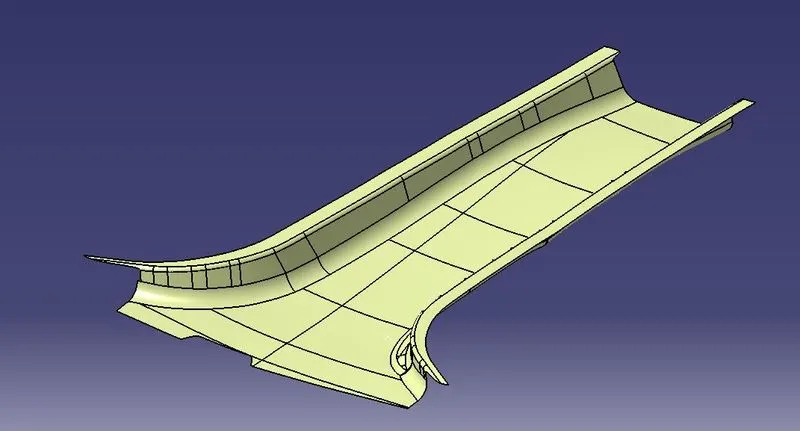
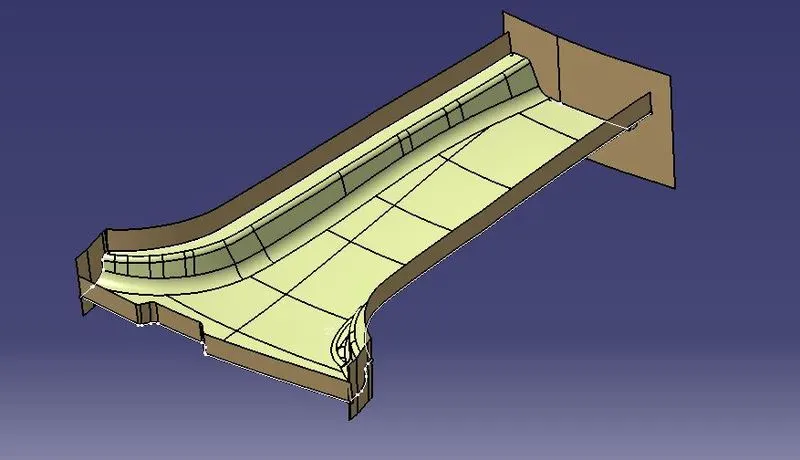
FLANGE CREATION
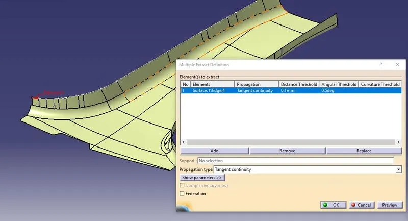
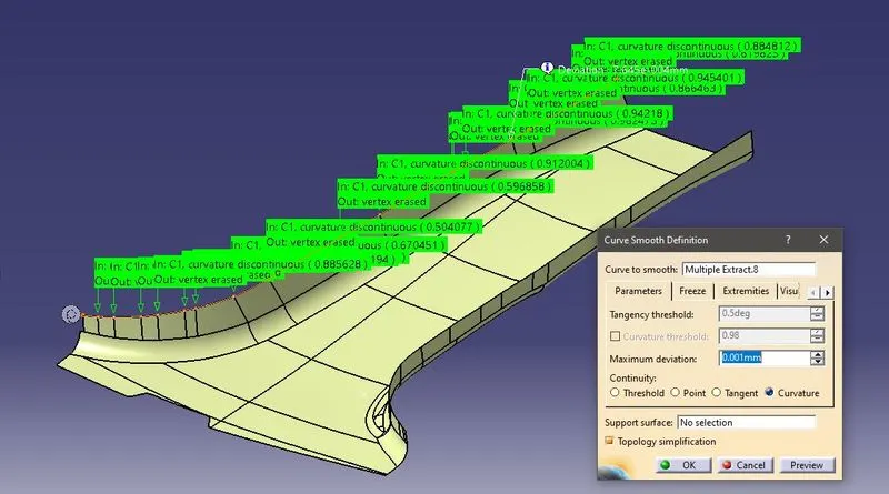
- Extract the edges class A Surface and make it smooth curve
- Extract the edge of the flange from the master section
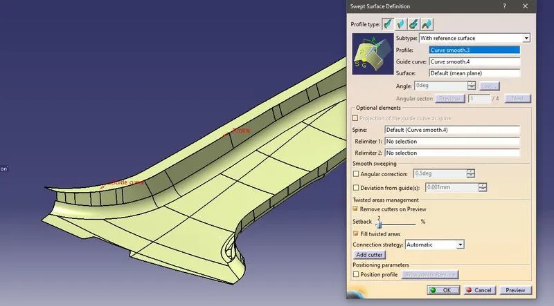
- Sweep the curve using sweep with reference surface Guide curve as the extracted sketch from master section and profile as the extracted edge from the class A
- Continue it for the all the edges
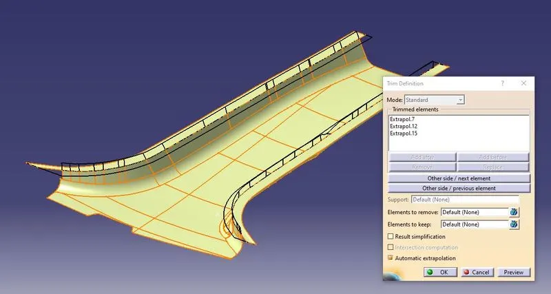
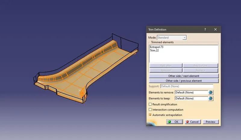
- Extrapolate the edges so that they intersect with each other
- And trim the edges to form the flange
B SURFACE CREATION
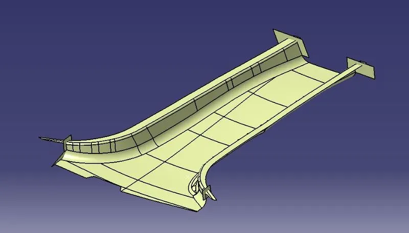
- Before creating B surface the flanges should be in the correct shape
- Create a line passing through the extra unwanted edges
- Extrude the created lines and split it
- Now improved Class A surface is created
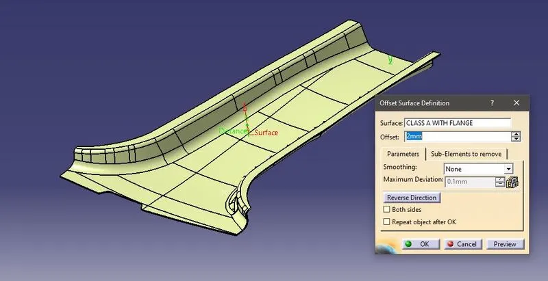
- Offset the Class A surface upwards with thickness 2mm
- The offset surface is Class B surface
C SURFACE CREATION
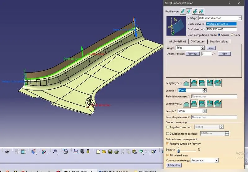
- All the edges of the class A surface is extracted and converted to smooth curve
- Sweep the edges with draft of 3deg outward in the direction of tooling axis
- Extrapolate the Swept surface so that they can intersect with each other
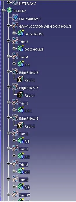
- Trim the surface
- Then the trimmed surface and the Class A surface is trimmed together to form a single surface
- Then the surface is trimmed with the class B surface to form a single closed surface. That is the Final C Surface
- Convert into body using close body option in part model
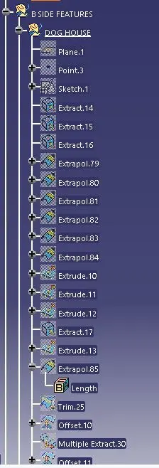
DOG HOUSE
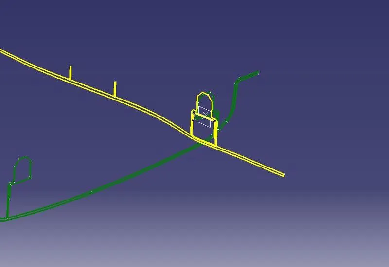
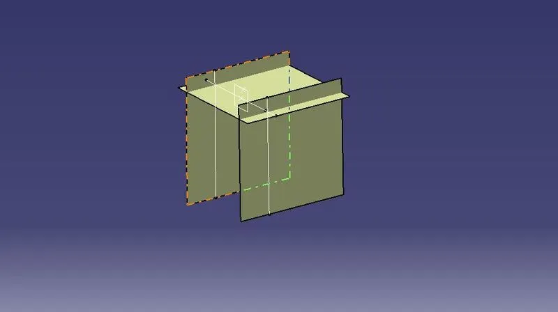
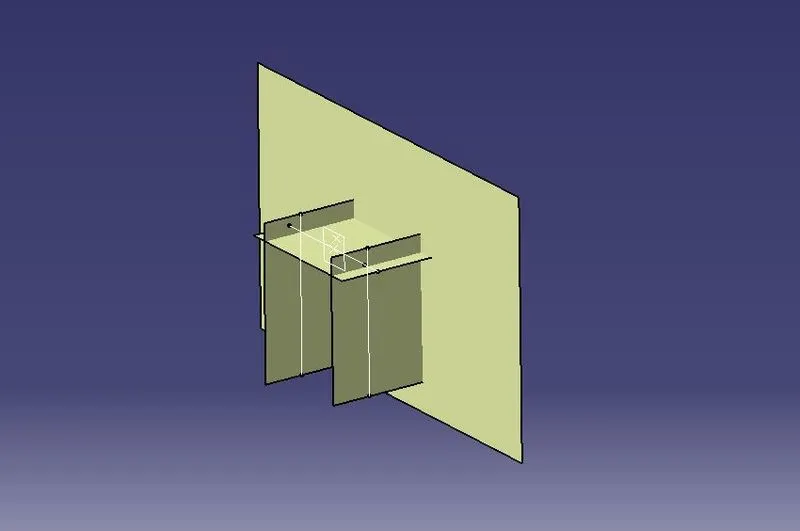
- To create Dog house from the master section.
- Extract the Edges of the master section and extrapolate it.
- Extrude the extracted surface in both direction
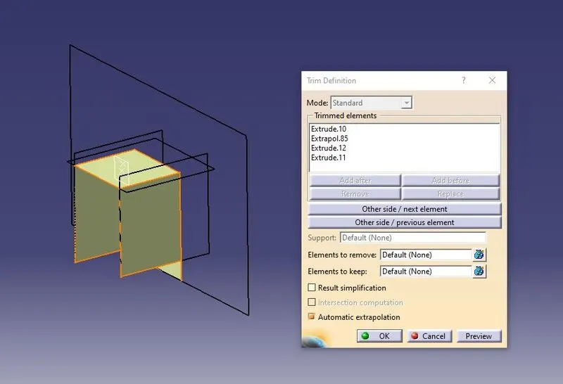
- The extracted surface is trimmed with one another
- The surface is now converted to solid body, and the split with the A surface
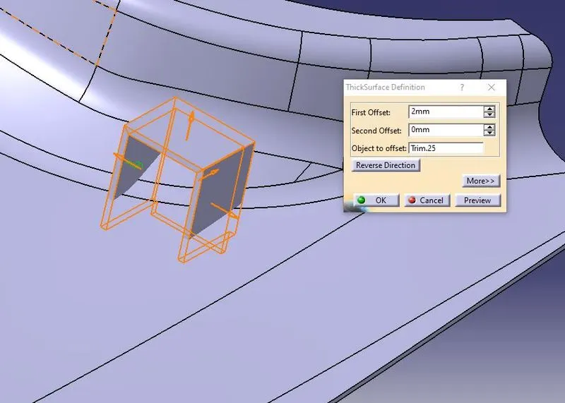
- To avoid sink mark on class A Surface, the bottom of the dog house is made 40% of thickness as per design.
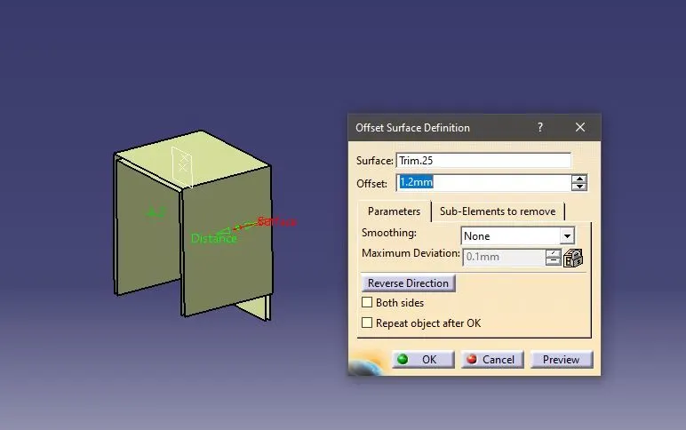
- Extract the class B surface and offset it to 3mm and inner wall of dog house at 1.2mm.
- Fillets are applied at the sharp corners
- Draft is applied along the tooling axis of 5deg
- Split the solid dog house with the surface created
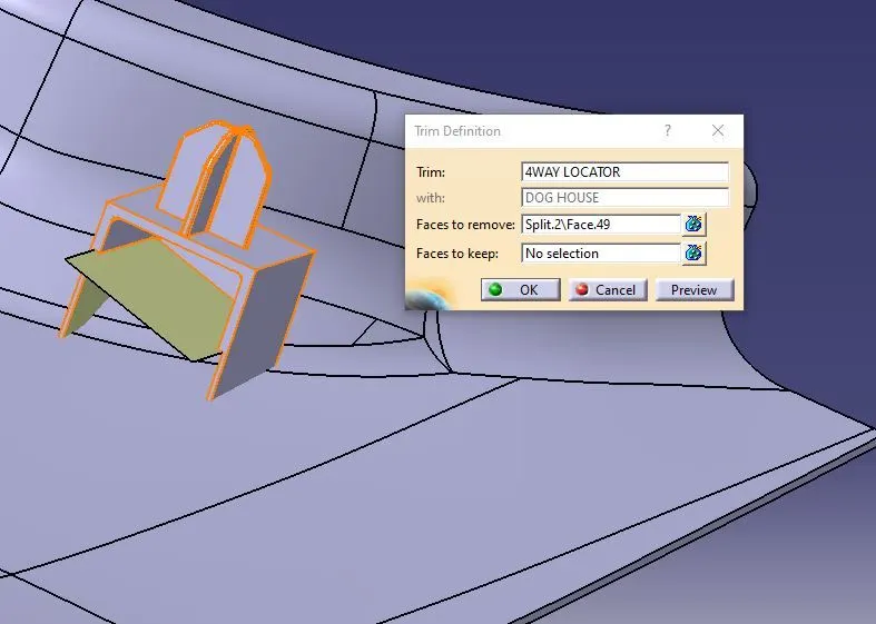
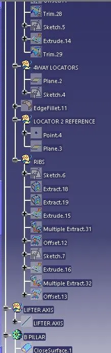
4 WAY LOCATOR
- 4 way locators are created on the top of the doghouse
- 4 Way locator sketch is created on the plane which top of the dog house
- It is extruded for the thickness of 1.2mm
- Chamfers, fillets and drafts are applied to the 4way locators
- Using Boolean operation 4way locator is added to dog house
- To create another dog house copy the dog house and paste special
- Create a plane using the master section
- Symmetry the dog house
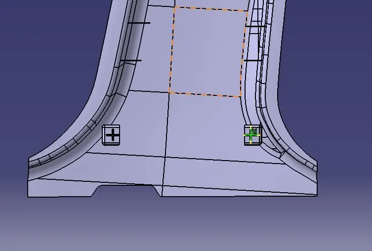
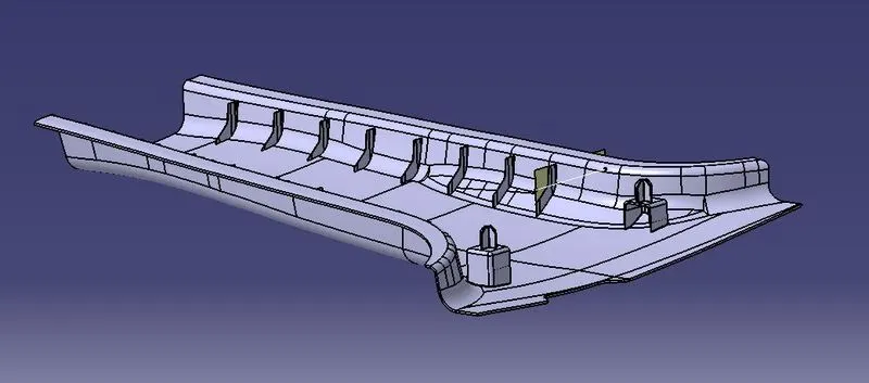
RIB CREATION
- A Positioned sketch is created on plane which we used to create locators
- This line is extrude and thicken to 0.8mm
- The body is split with the offset B surface and the solid body
- Fillet and the drafts are applied in the rib
- To create multiple ribs Rib is copy pasted and Translated
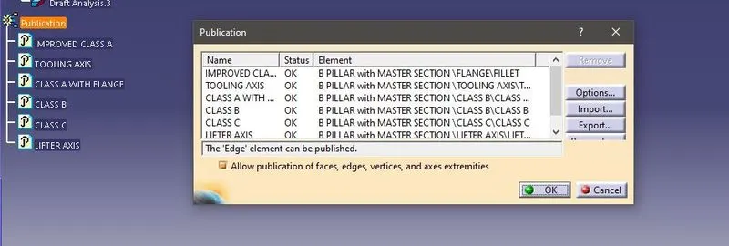
PUBLICATIONS
DRAFT ANALYSIS
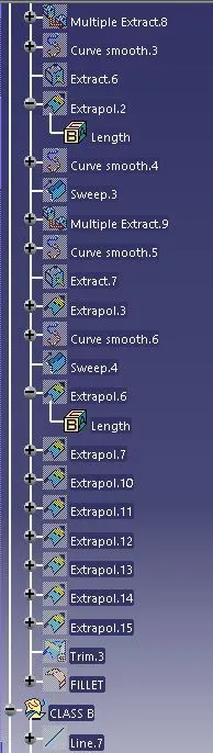
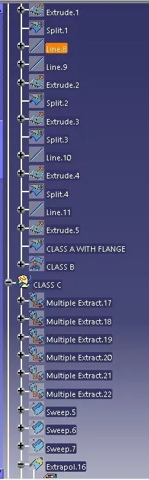
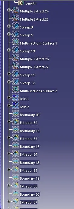
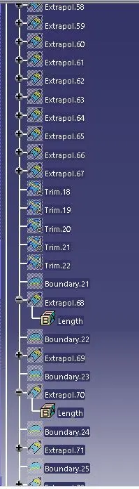
FEATURE TREE
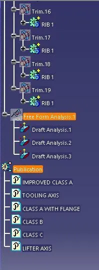
CONCLUSION
Thus the B pillar is created using given Class A and master section with engineering features