Advanced Sheet Metal Design Using NX Cad Challenge_7_ Metal bracket-II
ADVANCED SHEET METAL DESIGN USING NX CAD – BRACKET 2
OBJECTIVE
- To know basics of sheet metal module in NX CAD.
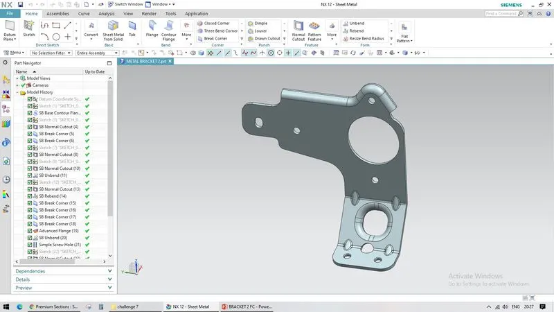
- To know the features like CONTOUR FLANGE, BEAD, BEND, HOLE, UNBEND, ADVANCED FLANGE, GUSSET.
INTRODUCTION
Metal having thickness from 0.1mm to 6mm are termed as sheet metal. Extremely thin are termed as foils or leaf above 6mm are called as plate. Sheet metal are used in various products used in automobile industry, aeronautical industry. There are many other metals that can be made into sheet metals such as aluminium, copper, stainless steel etc.,
DESIGN METHODOLGY / APPROACH
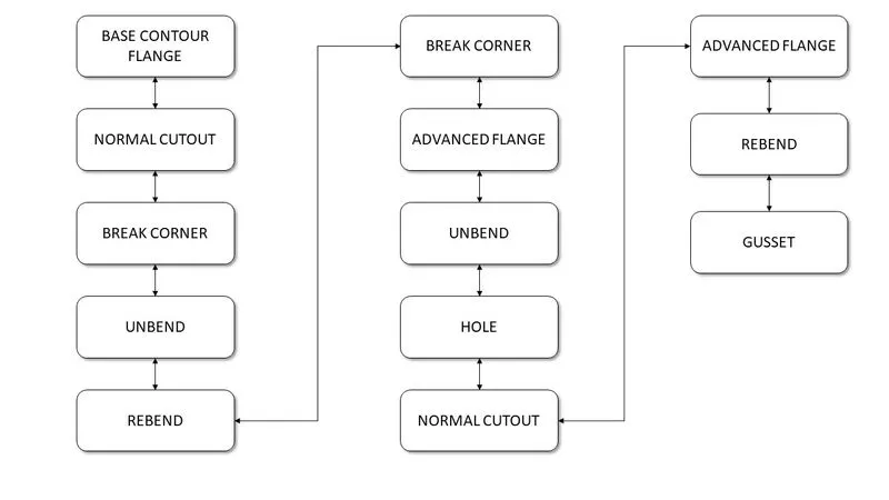
FEATURES USED
- CONTOUR FLANGE
- NORMAL CUT
- BREAK CORNER
- UNBEND
- BEAD
- REBEND
- HOLE
- ADVANCED FLANGE
- GUSSET
- CONTOUR FLANGE – CONTOUR FLANGE Creates a base feature by extruding a sketch along a vector, or adds material by sweeping a sketch along on edge or chain of edges.
- NORMAL CUTOOUT – NORMAL CUTOUT cuts a material by projecting a sketch onto the model and then cutting perpendicular to the faces intersected by the projection
- BREAK CORNER – Rounds or chamfers a sharp corner of a tab or flange
- UNBEND – UNBEND is used to flatten the sheet metal for further design
- HOLE – HOLE is used to create holes in the sheet metal part
- ADVANCED FLANGE – ADVANCED FLANGE add a flange along an edge using a bend angle or a reference face. The edge and reference face can be curved
- GUSSET – GUSSET creates a stiffening on the part mostly in the two edges
MODEL IMAGES
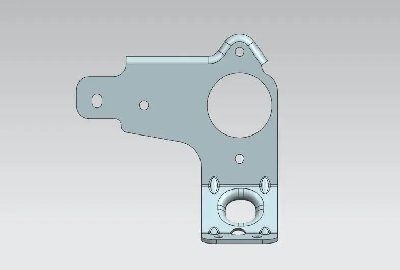
FRONT VIEW
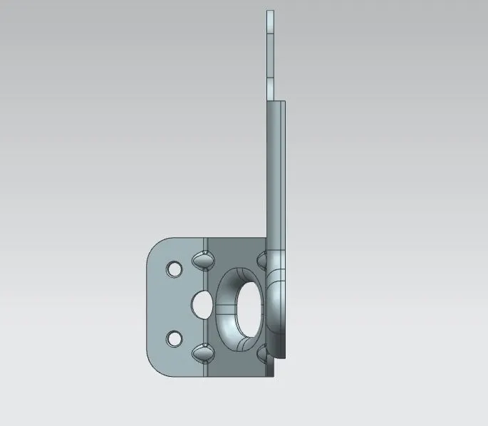
TOP VIEW
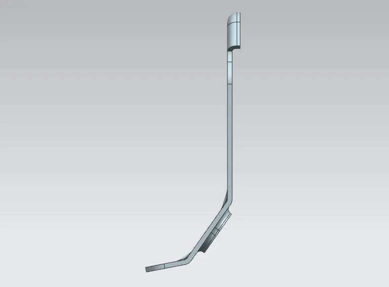
SIDE VIEW
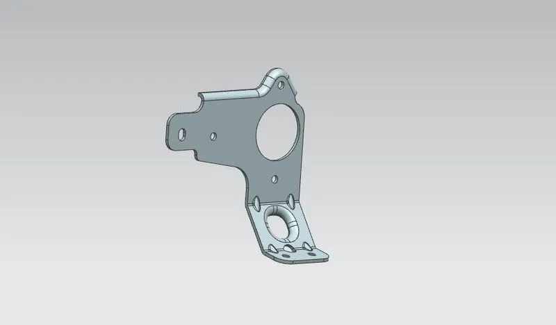
ISOMETRIC VIEW
CONCLUSION
Thus the Bracket model has been modelled in NX CAD.