Week 9 - Project 1 - Door Applique Design with Engineering Features
DOOR APPLIQUE DESIGN WITH ENGINEERING FEATURES
OBJECTIVE
- Create the door applique Plastic component through the given Class-A surface, and create tooling axis, perform draft analysis and also create Class-B surface& Class-C surface.
- Create engineering features like locators and heat stakes.
INTRODUCTION
The Draft allows the part to easily eject from the mold. The draft angle is to reduce friction between the core, cavity and part and it also avoid the damages. The minimum draft angle is 0.5 degree and the most common draft angle used in the plastic design is 3 degrees.
In CATIA the draft analysis is performed based on colour ranges identifying zones on the analysed element where the deviation from the draft direction at any point, corresponds to specified values.
Tooling direction is the main element that to be consider while designing a plastic component. In moulding machine the arrangement is given to open the mould along the direction. It is the direction in which the core and cavity opens.
CLASS A SURFACE
1.Visible surface and aesthetic look
2.Surface with textures
3.Surfaces provided by customer(OEM)
4.Don't have any features like(rib ,snap ,bosses etc.) on class A surface.
5.Class A surface is made from scanned data with different software like alias etc..
6.Surfaces which is having CURVATURE CONTINUITY IS CALLED class-A.
CLASS B SURFACE
1.Invisible Surfaces.
2.Surface mostly don't have textures
3.Surface need to be create according to class-A surface.
4.Having all features(Rib, boss, snap etc.) in B-side surface only.
5.Surfaces which is having TANGENT CONTINUITY IS CALLED class-B
CLASS C SURFACE
Which join both Class-A and Class-B Surface
LOCATING PINS
- These rib like structure on class B surface of plastic components which is used to position the child part with parent part while assembly.
- These locators are placed in the multiple location on the part depending upon the degree of freedom which needs to be arrested.
- They are classified into 4way and 2way locators depending upon their purpose and shape.
- Locators are used to locate a component to arrest its degree of freedom using 3-2-1 principle.
- The design rules for locating pins is same as Ribs
HEAT STAKES
- Manufacturing with thermoplastic components, its often necessary to join a thermoplastic part with part having dissimilar material, such as metal or any other thermoplastic.
- Heat stakes is an assembly method that uses the controlled melting and reforming of plastic stud or boss to capture or lock another plastic or metal component of assembly in place.
- The plastic stud protrudes through a hole in the component to be locked in place.
- Heated thermal tips are used to melt the top of the studs which fills up the volume of the cavity to produce a head locking the component in the place.
- The progressive melting of plastic under continuous pressure forms the head.
- When staking, the right combination of heat and pressure is critical.
- In short locators locate the component and lock the degree of freedom whereas the heat stakes is a fixation which locks the final degree of freedom.
- Heat stakes are the vertical cylindrical structures added to the class B surface. These are used to attach the child parts with parent part.
- This kind of attachment provides advantage of avoiding the additional fastening methods.
- Disadvantage of heat stakes is once its fixed it cannot be removed without damaging the component.
METHODOLOGY
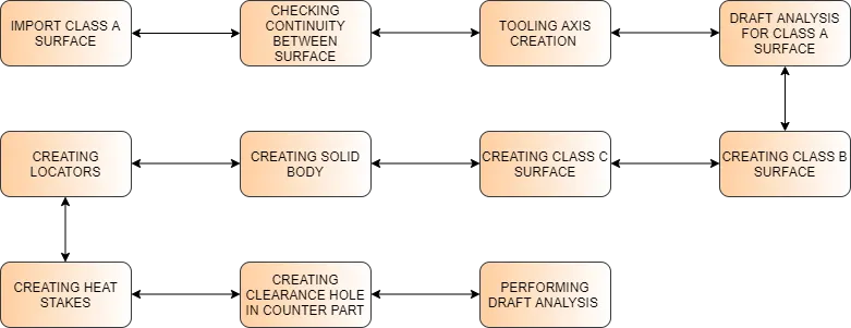
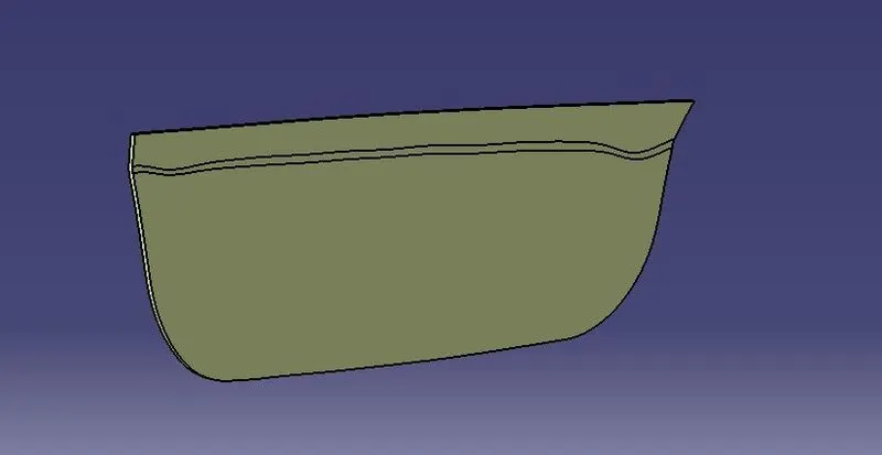
GIVEN CLASS – A SURFACE (DOOR APPLIQUE)
PROCEDURE
Continuity check:
- Input the class A surface
- After receiving the class A surface check the continuity of the given class a surface to ensure that there is no discontinuity in the class A surface. This can be checked using join or boundary option
TOOLING AXIS
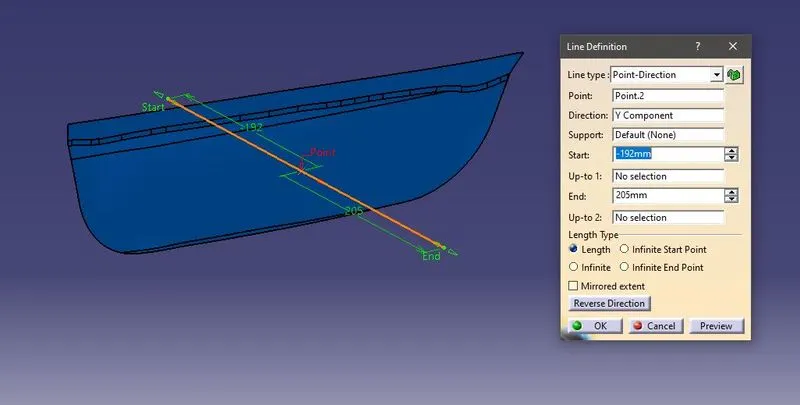
- Create a point at the centre of the surface using point definition. point type – on surface. Distance-0mm
- Create a line along the y direction using line definition. Line type – point-direction.
- This line will be our main tooling axis
DRAFT ANALYSIS
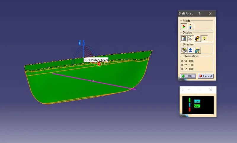
- For plastic parts the Nominal draft angle is 3deg, but even 7deg is allowed for the subassemblies like ribs and slots
- INSERT - ANALYSIS - FEATURE DRAFT ANALYSIS
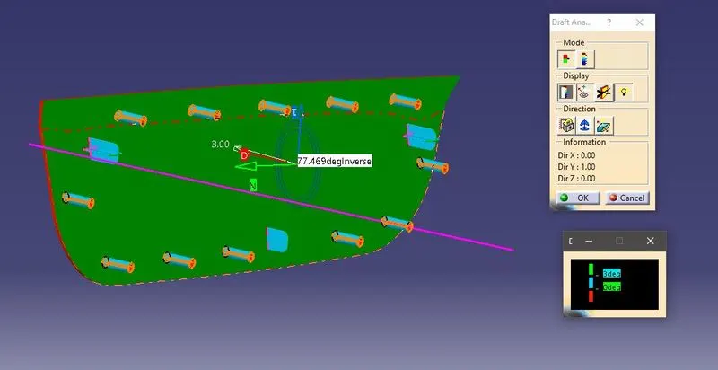
- First the compass is moved to the part (the compass should be placed on the tooling axis) which used to define the new current draft direction, then lock the draft direction using the lock icon
- The colour chart indicates the various condition of the draft angle. the green colour indicates that the part passes and the and can be used for the further operations
- By using the analysis under the running point icon we can check draft angle at the various surfaces of the component
- There are two modes in the Draft analysis quick mode and fully detailed mode
CLASS B SURFACE
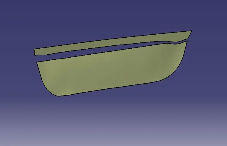
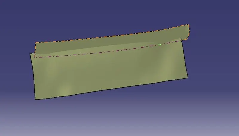
- Extract the Class A surface using extract option.
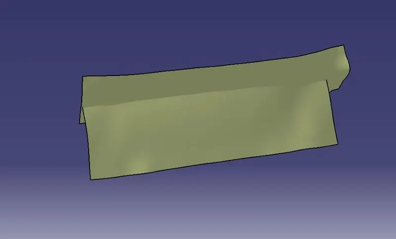
- Untrim and extrapolate both the surface such that they intersect each other
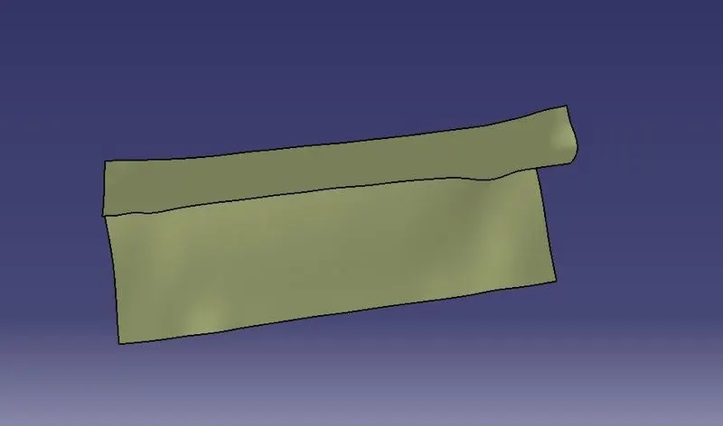
- Trim both the surfaces by trimming unwanted surfaces
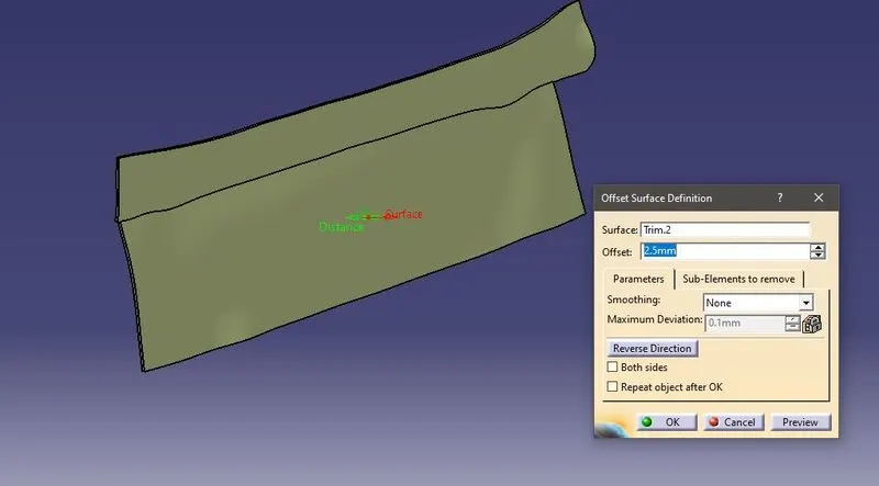
- Offset the surface to 2.5mm
- Apply the appropriate fillet to the surface
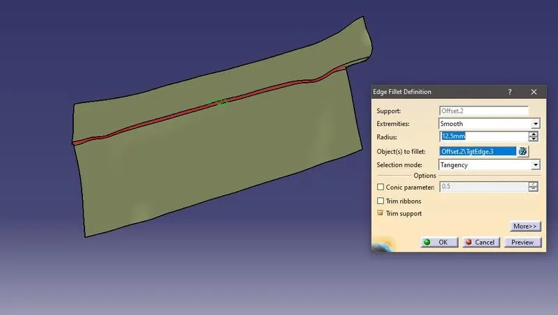
CLASS C SURFACE
- Create the lower edge boundary using boundary option
- Make the boundary smooth using curve smooth option
- Create surface sweep using with draft direction sub option selecting draft direction as tooling axis
- Repeat the above steps to the upper edge
- Extrapolate all the edges such that they intersect with each other
- Trim the surface to create single surface
- Join the trimmed surface with class A surface
- Trim the joined surface with class B surface
- Class C surface is obtained
- Convert C surface into solid body using closed surface option
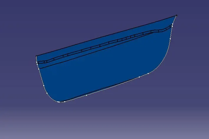
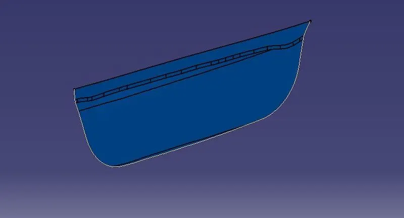
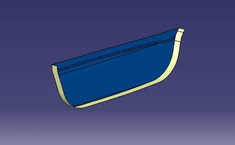
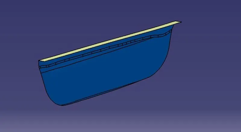
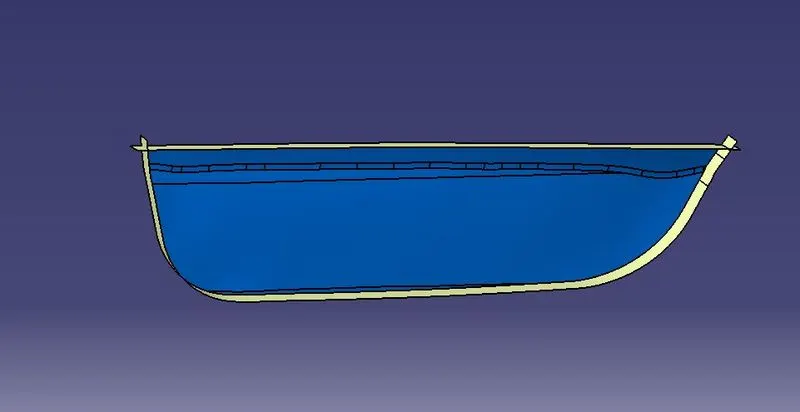
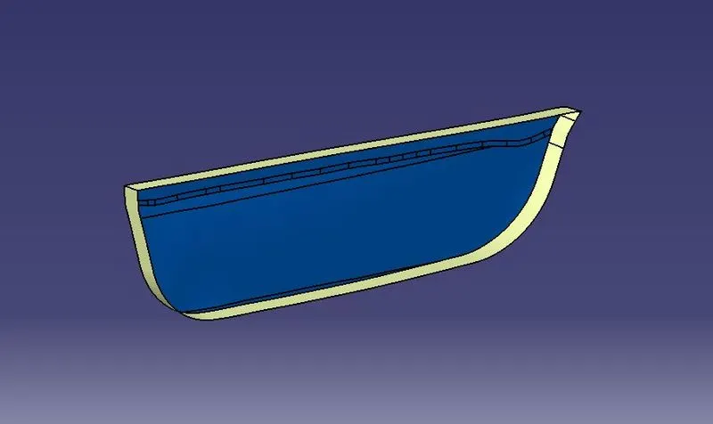
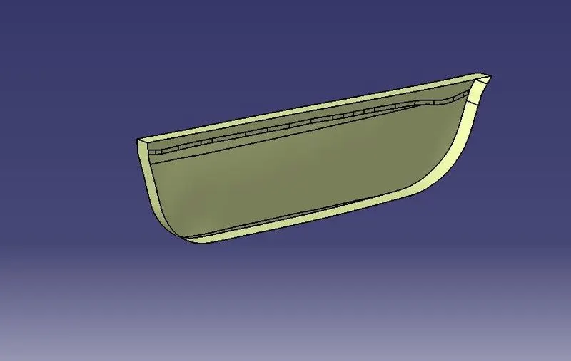
LOCATORS CREATION
- Create a point on the counterpart surface using point definition. point type – on surface. Distance-0mm
- Create a plane using the point and zx plane as reference
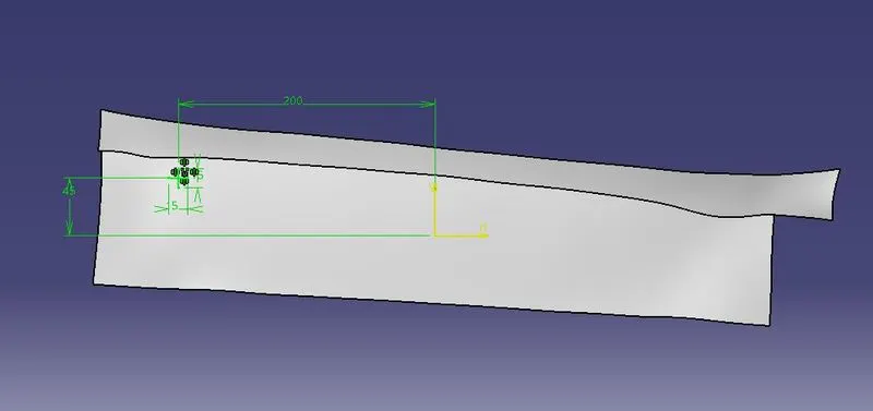
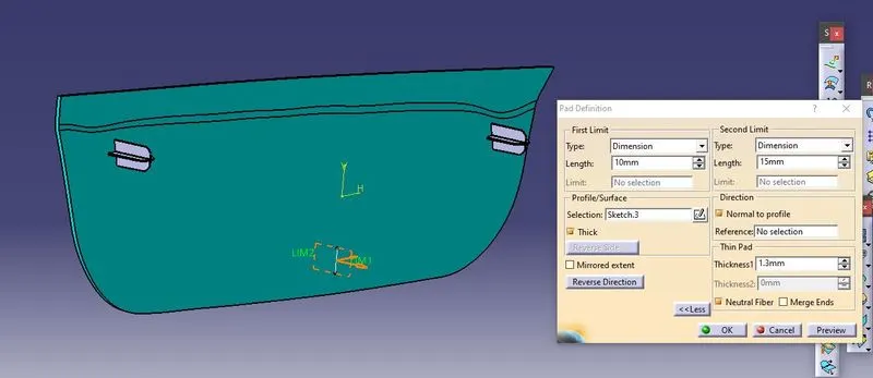
- Create a positioned sketch on the plane for the 4way locator
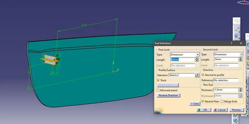
- Pad the sketch using port model and thicken the sketch using neutral fibre option
- Use the design rule (thickness should be 40% of the component wall thickness)
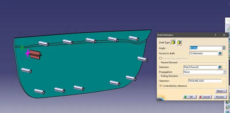
- Apply 0.5deg draft on the vertical surfaces of the padded body base surface of the body as neutral surface and tooling axis as pulling direction
- Create entry chamfer to the body
- Apply fillet to avoid the sharp edges
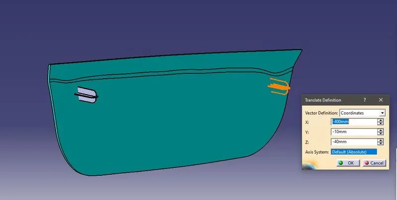
- To create another 4way locator simply copy and paste the 4way locator body and relocate it using translate option w.r.t coordinates
- Create the 2way locator as same as the 4way locator only the sketch and the position varies
- By using the Boolean operation union trim the locators
HEAT STAKES CREATION
- Create a boundary using boundary option on the lower edge of the class A surface
- Make the boundary smooth using curve smooth option
- Create a parallel curve with distance 15mm. make the parallel curve smooth using smooth curve option
- Repeat the same steps to create curve on the top edge
- Make points on both the parallel curves at instances using points by repetition
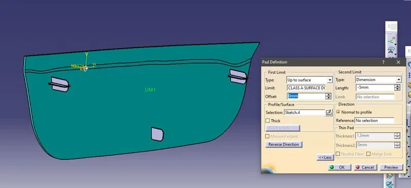
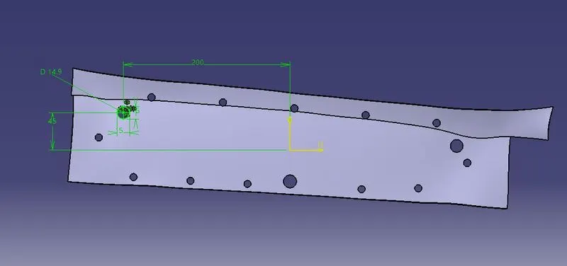
- Create the heat stakes sketch on the created plane used for locators and the created point
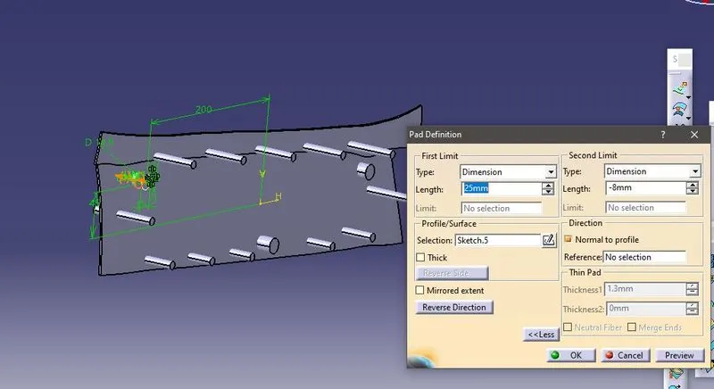
- Pad the sketch to the required distance
- Make sure that length of the heat stakes is lesser than the locators and also not much nearer to the locators
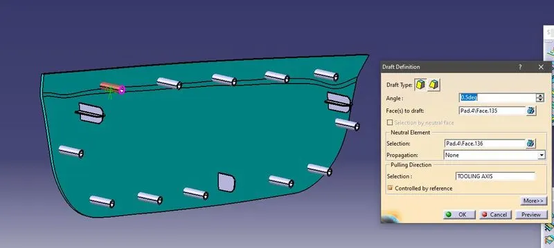
- Give Draft to the heat stakes
- To create another heat stakes in the specified locations simply copy and paste special the heat stakes. Translate the heat stakes to specified points use point to point option in the translate option
- By using Boolean operation Union trim the heat stakes body with the door applique solid body
CREATING CLEARANCE IN COUNTER PART
- Thicken the door attachment surface by thicken option using part design.
- Give thickness as 2.5mm.
- In the solid body create the same sketch as the locator and heat stakes with 0.5mm clearance per side.
- Give 0.5deg draft along tooling axis to the padded body.
- Using Boolean operation remove the padded body from the counterpart so that the clearance is achieved.
Perform draft analysis to the solid body (door applique)
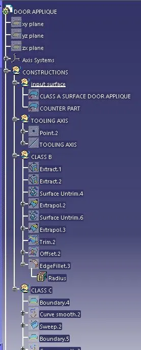
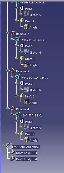
FEATURE TREE
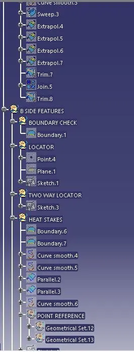
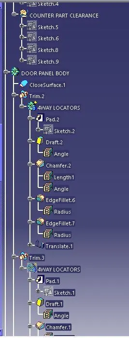
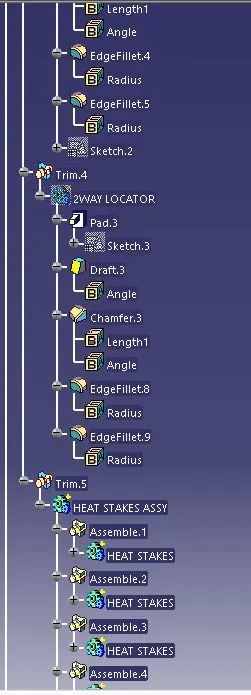
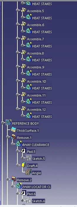
CONCLUSION
Thus the class B, class C surface were created and engineering features like locators and heat steaks where created . draft analysis is performed successfully