Courses by Software
Courses by Semester
Courses by Domain
Tool-focused Courses
Machine learning
POPULAR COURSES
Success Stories
Week 9 - Parametric study on Gate valve.
Aim: To perform a parametric study on Gate valve. Objective: Simulate the flow of fluid through a gate valve. Perform the parametric study on the gate valve by setting design points corresponding to the positions of the lift of the spindle. Calculate the mass flow rate corresponding to all the design points Gate…
Aatas A G
updated on 07 Dec 2022
Aim:
To perform a parametric study on Gate valve.
Objective:
- Simulate the flow of fluid through a gate valve.
- Perform the parametric study on the gate valve by setting design points corresponding to the positions of the lift of the spindle.
- Calculate the mass flow rate corresponding to all the design points
Gate valve:
A gate valve, also known as a sluice valve, is a valve that opens by lifting a barrier (gate) out of the path of the fluid. Gate valves require very little space along the pipe axis and hardly restrict the flow of fluid when the gate is fully opened. The gate faces can be parallel but are most commonly wedge-shaped (in order to be able to apply pressure on the sealing surface).

Theory:
Gate valves work by inserting a rectangular gate or wedge into the path of a flowing fluid. They are operated by a threaded stem which connects the actuator (generally a hand wheel or motor) to the stem of the gate. If the valve has a rising stem its position can be seen just by looking at the position of the stem. A gate valve is used to control the fluid flow through lifting and descending the gate. A gate distinct feature is to provide an unobstructed passageway, which includes minimal pressure loss over the valve.
When the gate is fully opened there is no restriction to the flow hence the pressure drop is low comparatively. Generally, the gate valve are fully closed or fully open as partially opened valve may experience vibration which may lead to excessive wear. A gate valve's main component is body, seat, gate, stem, bonnet, and actuator. the primary mechanism is straight forward where the handwheel is rotated to move the gate up and down via threads. they require more than a 360-degree turn to fully open the valve.
Gate valves tend to be slightly cheaper than ball valves of the same size and quality. They are slower in actuation than quarter-turn valves and are for applications where valve operation is infrequent, such as isolating valves. Gate valves should be used either fully open or fully closed, not to regulate flow. Automated gate valves exist with either an electric or pneumatic actuator, but a manual gate valve is cost-effective since they have infrequent usage. Gate valves are widely used for all types of applications and are suitable for both above-ground and underground installation. They are suitable for most fluids including steam, water, oil, and gas, etc.
Functioning Principle:
Main Components of a Gate Valve are: body, seat, stem, bonnet and actuator. The main operation mechanism is very simple. When the hand wheel is turned, it rotates the fluid, which is translated into the vertical movement of a Gate Disc via threads. They are considered multi-turn valves as it makes more than one 3600 turn to fully open/close the valve. When the Gate is lifted from the path of the flow, the valve opens and when it returns to its closed position, it seals the bore resulting in a full closure of the valve.

Applications of Gate Valve:
Gate valves are used to shut off the flow of liquids rather than for flow regulation. When fully open, the typical gate valve has no obstruction in the flow path, resulting in very low flow resistance. The size of the open flow path generally varies in a nonlinear manner as the gate is moved. This means that the flow rate does not change evenly with stem travel. Depending on the construction, a partially open gate can vibrate from the fluid flow.
Parametric Study:
One of the best ways to get value out of your simulation is to do parametric analysis. With very little marginal work a completed model can be parameterized to simulate scenarios limited only by your computational time and resources. As you move forward in your design, you can assess the impact that changing certain parameters can have on the design. The parameters can include dimensional parameters. Parametric studies allow you to nominate parameters for evaluation, define the parameter range, specify the design constraints, and analyze the results of each parameter variation.
A parametric study requires the following:
Design Objective is set to Parametric Dimensions
Parameters nominated for use in the simulation
Parameter ranges identified
Design criteria specified
Various configurations generated
When you have the configurations generated you can then evaluate your simulation. You can further refine the parameters or design constraints until satisfied with the results.Once you determine that a configuration satisfies your design needs, you are able to promote that configuration back to the model as a CAD edit. You are prompted whether to make changes.
Flow Coefficient:
The flow coefficient of a device is a relative measure of its efficiency at allowing fluid flow. It describes the relationship between the pressure drop across an orifice valve or other assembly and the corresponding flow rate. Mathematically the flow coefficient Cv (or flow-capacity rating of the valve) can be expressed as:

where,
Q is the rate of flow (expressed in US gallons per minute),
SG is the specific gravity of the fluid (for water = 1),
ΔP is the pressure drop across the valve (expressed in psi).
10pa=0.00145038psi
In more practical terms, the flow coefficient Cv is the volume (in US gallons) of water at 60 °F that will flow per minute through a valve with a pressure drop of 1 psi across the valve. The use of the flow coefficient offers a standard method of comparing valve capacities and sizing valves for specific applications that are widely accepted by the industry. The general definition of the flow coefficient can be expanded into equations modeling the flow of liquids, gases, and steam using the discharge coefficient.
Flow Factor:
The metric equivalent flow factor (Kv; commonly used in Europe and Asia) is calculated using metric units:

Kv can be calculated from Cv using the equation as given below:

The Kv factor of a valve indicates "The water flow in m3/h, at a pressure drop across the valve of 1 kgf /cm2 when the valve is completely open.
Geometry:
Import the gate valve file into space claim

The above is the model analysed in Ansys fluent. It has the main features of a gate valve. The components of the gate valve are the Handwheel, Spindle, Bonnet, Gate Disc, Bottom part. Initially, the valve is fully closed. We have to increase the lift of the gate disc for every design point of the parametric study. We use the parameter option to parametrize the lift of the Gate Disc. The lift is given by using the "move" command in Ansys Spaceclaim, after that we extract the fluid volume. We use the "pull" command to create the pipe geometry.
Initial Lift

Hide the "Bottom " Part , so we can claerly see the "Gate Disc".
Then Select "Gate Disc" component and move it in upward direction by "10 mm" lift.
To analyze the flow and its effects, we must allow the flow, and for that we have given "10 mm" lift to the "Gate Disc".

Here we can see the green color arrow in upward direction, which shows the movement of "Gate Disc" in positive Z-Direction.
Also we can see the symbol of "P".
This symbol "P" is used to parametize the lift of the "Gate Disc".
After selecting the symbol "P", it turns in Grey color, and message shows that a Group has been vreaated for lift.
Created group for lift parameter shown in above image.
On the Left Side, in Tree Structure,if we see the group options, we can see created group and the amount of parameter, which has been set 10 mm lift.
We can simply change the value of parametrs from there directly.
Lift adjustments:
Case-1: Lift adjustment=10mm in positive z direction.

Case-2: Lift adjustment=20mm in positive z direction.

Case-3: Lift adjustment=30mm in positive z direction.

Case-4: Lift adjustment=40mm in positive z direction.

Case-5: Lift adjustment=50mm in positive z direction.

Initial Gate Disc position (fully closed)

Gate Disc position (Partially open)

Fluid Volume Extraction
update the volume body in context

supress all other components other than fluid volume

Mesh:
First name inlet and outlet

We use the default computational mesh. Element size = 92.892 mm.

Sectional View

Element Quality

Set up:
- Solver: Steady
- Type: Pressure Based
- Gravitational Acceleration: X: 0, Y: 0, Z: -9.81 m/s2
- Turbulence Model: Realizable k- epsilon with Standard Wall Function
5.Cell Zone Condition: Fluid: Water
- Material Specifications:
- Material: water-liquid (H2o)
- Density: 998.2 Kg/m3
- Viscosity: 0.001003 Kg/m-s
- Boundaries:
- Inlet: Pressure = 10 Pa (Gauge Pressure)
- Outlet: Pressure= 0 Pa (Gauge Pressure)
- Solution Methods: Coupled
- Initialization:
- Method: Standard Initialization from the Inlet
- Number of Iteration: 500

In above image, we can see that Velocity at the inlet will be 0.1415488 m/s in Y-direction
So, for Reynolds No,
ρ=998.2Kg/m3
V = 0.14145488 m/s
D = 0.1 m
Re=(ρ⋅V⋅D)/μ
= [998.2*0.1415488*0.1]/0.001003
= 14087.14
Here, Reynolds No is 14087.14, which is more than 2000.
So the flow is turbulent.
So the viscous model will be K-Epsilon.
After initialization, Report Definitions for the report of Mass Flow Rate at the Outlet is created.
Also Contours for Velocity Magnitudes is created.
Animations for the flow of water inside Gate Valve based on Contours is created.
But here, we have given Pressure Inlet, instead of Velocity Inlet. So knowing the velocity of the flow for correct Reynolds No. is required.
So, to know the velocity of the flow, we have to go for initializing the solution.
So, go to Solution, and select Standard Initialization, and Initialize from Inlet.
After initialization, we can get the correct velocity and calculate the Reynolds No. and from that, we can decide for the appropriate viscous model.


OUTPUT:
Parametric Study Of Mass Flow Rate

Tabulations:
|
Lift in (mm) |
Flow rate (Q) in kg/s |
Flow rate (Q) in gpm |
Flow Co-efficient Cv |
Flow factor Kv |
|
10 |
-0.14798 |
2.345532 |
61.58862 |
53.27416 |
|
20 |
-0.23001 |
3.645735 |
95.72915 |
82.80571 |
|
30 |
-0.34552 |
5.476607 |
143.8039 |
124.3904 |
|
40 |
-0.45 |
7.132649 |
187.288 |
162.0041 |
|
50 |
-0.55398 |
8.780767 |
230.564 |
199.4379 |
|
60 |
-0.65431 |
10.37103 |
272.3209 |
235.5576 |
|
70 |
-0.77066 |
12.21522 |
320.7453 |
277.4447 |
|
75 |
-0.79846 |
12.65586 |
332.3155 |
287.4529 |
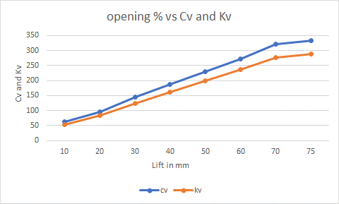
Cv-Flow coefficient, Kv-Flow factor
Conclusion:
- Mass flow rate gradually increases as the lift of gate disc is increased.
- The variation of flow coefficient and flow factor with the opening of the valve is studied by using parametric.
- Parametric study is time reducing option when studying the effects of changes of certain parameters on a system.
- Flow coefficient plays important role in the selection of valve and sizing of a valve, so calculating it is necessary.
- flow coefficient also helps in computing the efficiency of the system and the effect of pressure on the system.
Leave a comment
Thanks for choosing to leave a comment. Please keep in mind that all the comments are moderated as per our comment policy, and your email will not be published for privacy reasons. Please leave a personal & meaningful conversation.
Other comments...
Be the first to add a comment
Read more Projects by Aatas A G (50)
Week 4 - CHT Analysis on Exhaust port
AIM: To perform the simulation of Conjugate heat transfer analysis on given exhaust port geometry by using ANSYS FLUENT. OBJECTIVE: To study the importance of Conjugate heat transfer analysis and importance of y+ value during meshing of the components. To perform the simulation of Conjugate heat transfer analysis on given…
12 Dec 2022 08:19 AM IST
Week 10 - Simulating Combustion of Natural Gas.
AIM To perform a combustion simulation on the combustor model. Objective Part I Perform a combustion simulation on the combustor model and plot the variation of the mass fraction of the different species’ in the simulation using line probes at different locations of the combustor as shown in Fig. You need to plot…
07 Dec 2022 11:26 AM IST
Week 9 - Parametric study on Gate valve.
Aim: To perform a parametric study on Gate valve. Objective: Simulate the flow of fluid through a gate valve. Perform the parametric study on the gate valve by setting design points corresponding to the positions of the lift of the spindle. Calculate the mass flow rate corresponding to all the design points Gate…
07 Dec 2022 10:12 AM IST
Project 2
AIM: To deal with the development of a forward energy-based fuel consumption model of a P1 hybrid vehicle. OBJECTIVE: Load the Project2 folder as the Current Folder in Matlab. Run the “Project2_InitFile.m” Matlab script. Copy the Conventional vehicle Simulink model created for Project 1 in this folder. Figure…
25 Oct 2022 01:11 PM IST
Related Courses


0 Hours of Content

Skill-Lync offers industry relevant advanced engineering courses for engineering students by partnering with industry experts.
Our Company
4th Floor, BLOCK-B, Velachery - Tambaram Main Rd, Ram Nagar South, Madipakkam, Chennai, Tamil Nadu 600042.
Top Individual Courses
Top PG Programs
Skill-Lync Plus
Trending Blogs
© 2025 Skill-Lync Inc. All Rights Reserved.


