Week 9-Challenge
Mesh the given Component with a Mesh size of 5mm.
Create connector and Attach the various parts of the given model
- Right_Rail_2 & Front_truss_1:- Seam-Quad(angled+capped+L)
- Left_Rail_2 & Front_truss_1:- Quad elements
- Front_truss_2, Front_truss_1 & Right_Rail_1:- Spot weldwith 3 Layers and 5 mm Diameter
- Front_truss_2, Front_truss_1 & Left_Rail_1:- Hexa (Adhesive)
- Rear_truss_2 & Right_Rail_2:- Bolt Connector
- Rear_truss_2 & Left_Rail_2:- Bolt Connector
- Right_Rail_1 & Right_Rail_2:- Spot-weld with Rigid Elements
- Left_Rail_1 & Left_Rail_2:- Spot-weld withSpring Elements
- Rest all the component left Join them with suitable connectors
Importing the model:
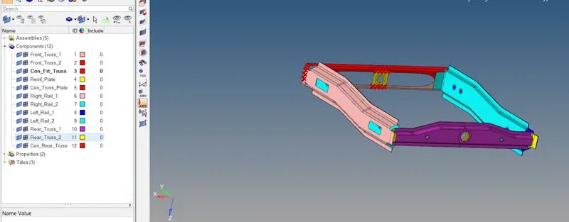
Creation of Mesh: 2D -- > automesh
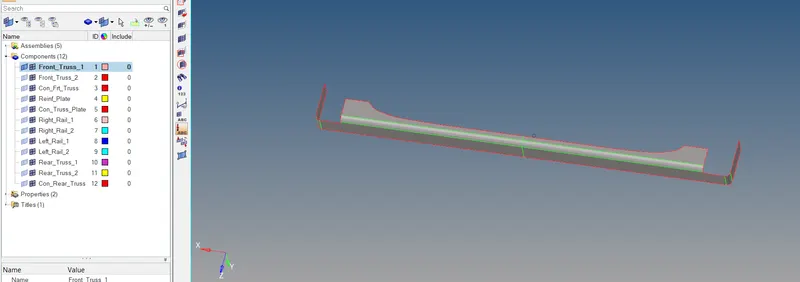
- Hide all components leaving the component which is to be meshed.
- Start meshing every component one by one with target element size of 5mm.
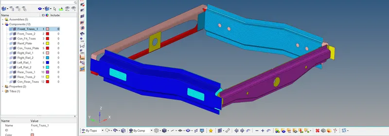
- Completely meshed all the components.
Create connector and Attach the various parts:
- Right_Rail_2 & Front_truss_1:- Seam-Quad(angled+capped+L)
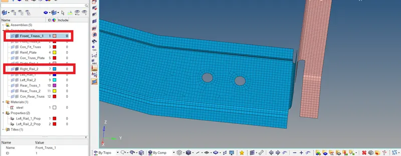
- Hide all the components mesh’s only leaving the components mesh’s which are to be attached.
- This is done to avoid any miss section of nodes or components in any tool.

- Go to 2D -- > connectors.
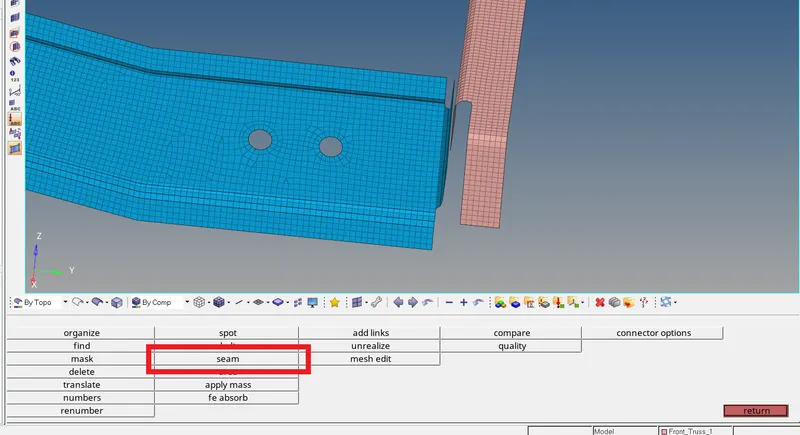
- Click on seam to create a seam connector.
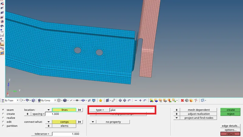
- Click on type to select the required connector in seam.
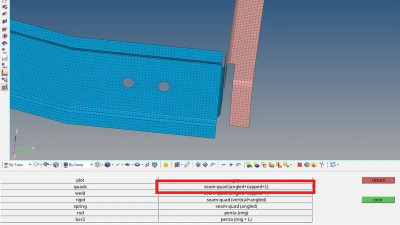
- Now select the seam-quad(angled+capped+L) which is the required connector.
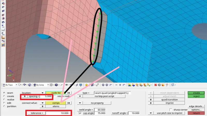
- Select the nodes to which the connection is to be established.
- Enter the spacing value of the connectors near to the mesh size value.
- Select the components to be connected.
- The tolerance value is to find the elements to attach with in the tolerance range.
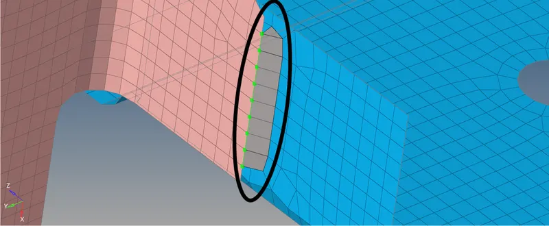
- Seam-Quad(angled+capped+L) connection is established between the required components.
- Left_Rail_2 & Front_truss_1:- Quad elements
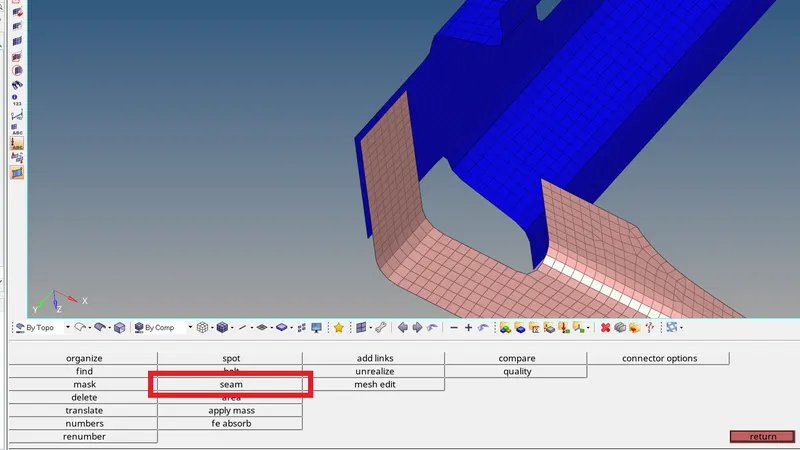
- Click on seam to create a seam connector.
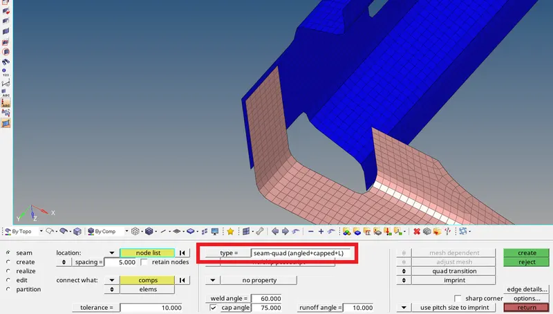
- Click on type to select the required connector in seam.
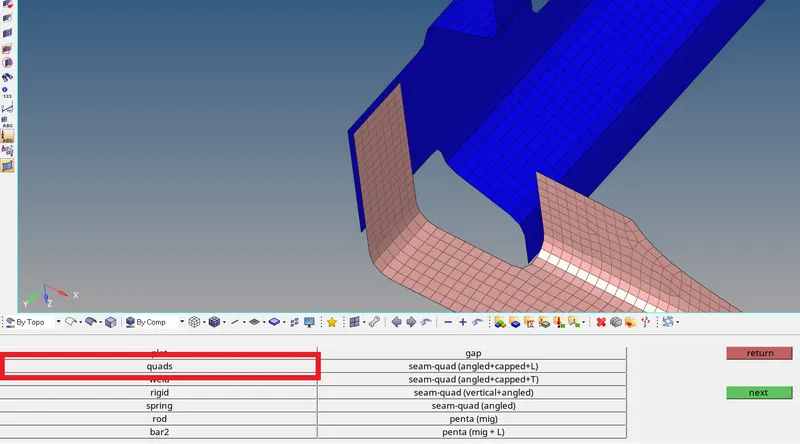
- Now select the quads which is the required connector.
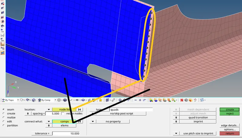
- Select the nodes to which the connection is to be established.
- Enter the spacing value of the connectors near to the mesh size value.
- Select the components to be connected.
- The tolerance value is to find the elements to attach with in the tolerance range.
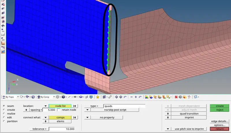
- Quad connection is established between the required components.
- Front_truss_2, Front_truss_1 & Right_Rail_1:- Spot weldwith 3 Layers and 5 mm Diameter
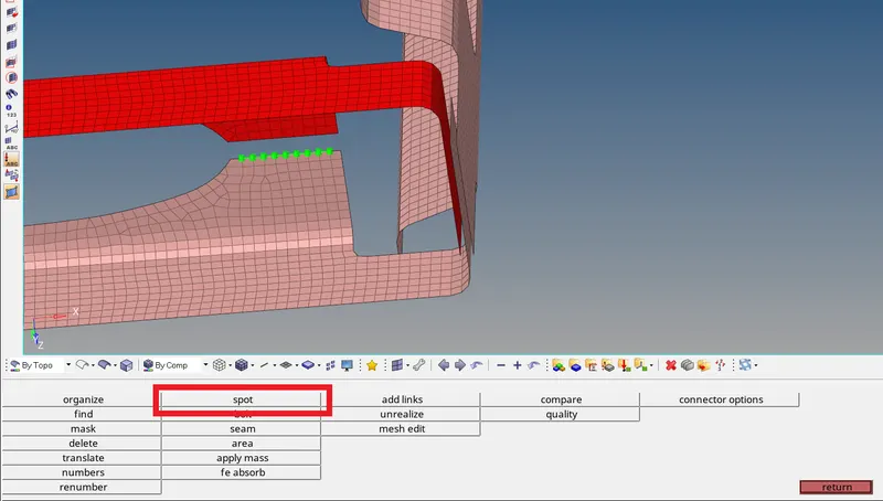
- To create a spot weld connection go to 2D -- > connectors -- > spot.
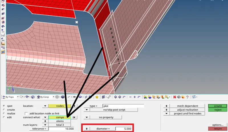
- Select the nodes to which the connection is to be established.
- Select the components to be connected.(3 components-3 layers)
- The tolerance value is to find the elements to attach with in the tolerance range.
- Enter the diameter value as required (5mm).
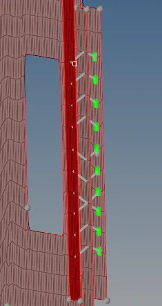
- Spot Weld connection is established between the required components.
- Front_truss_2, Front_truss_1 & Left_Rail_1:- Hexa (Adhesive)
- Go to 2D -- > connectors.

- Click on seam to create a seam connector.

- Click on type to select the required connector in seam.
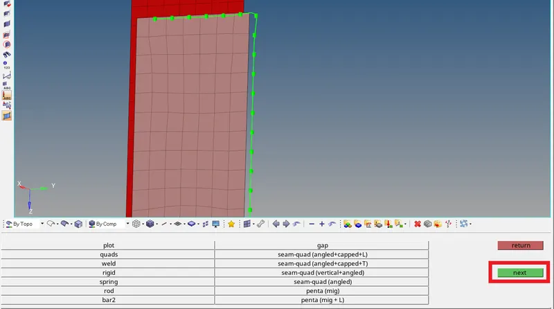
- Click on next to see more type of connectors.
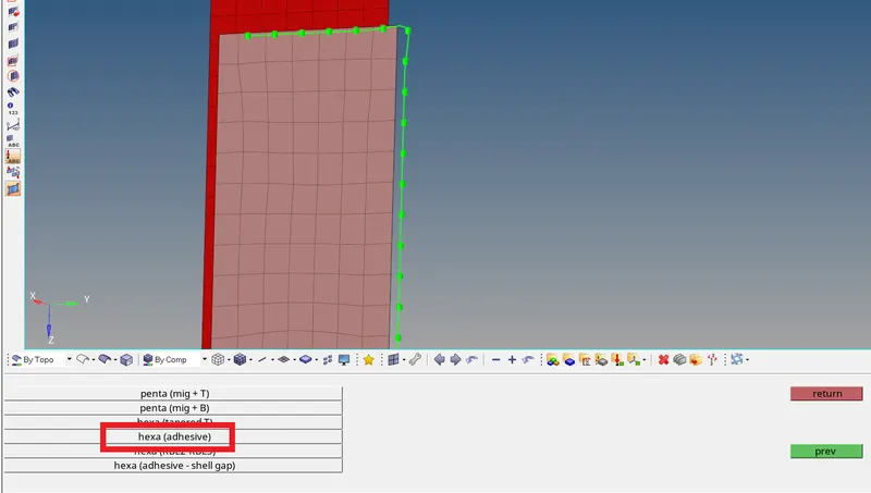
- Select hexa(adhesive).
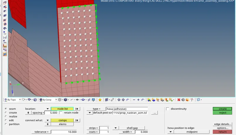
- Select the nodes to which the connection is to be established.
- Enter the spacing value of the connectors near to the mesh size value.
- The tolerance value is to find the elements to attach with in the tolerance range.
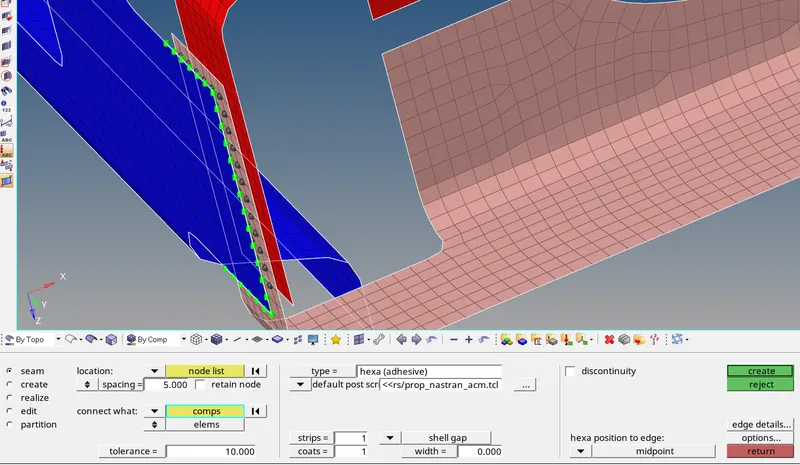
- Select the 3 component’s witch are to be connected with hexa (adhesive) connector.
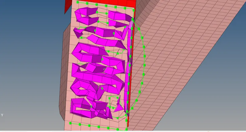
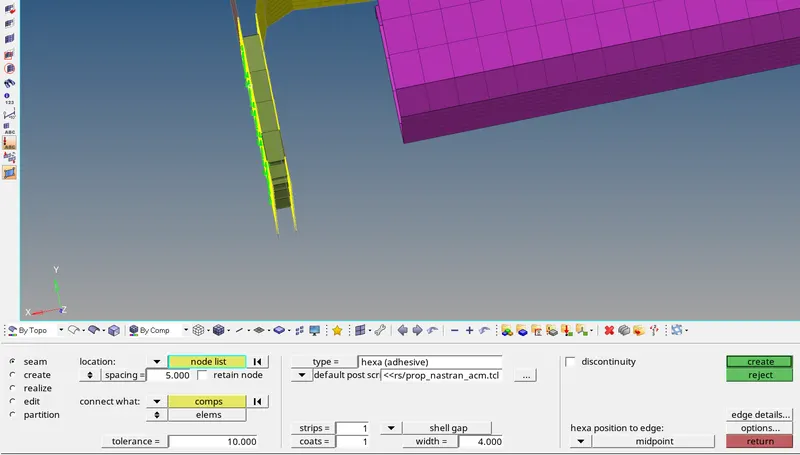
- Hexa (Adhesive) connection is established between the required components.
- Rear_truss_2 & Right_Rail_2:- Bolt Connector
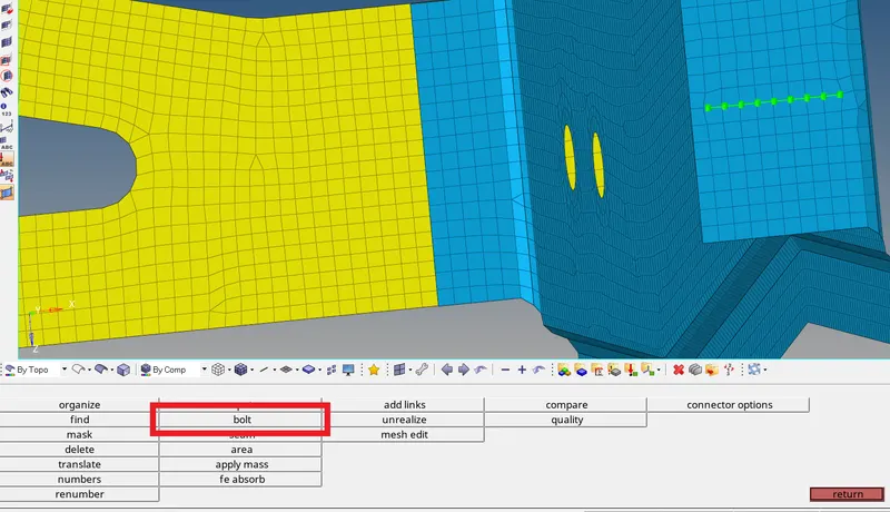
- To create a Bolt connection go to 2D -- > connectors -- > bolt.
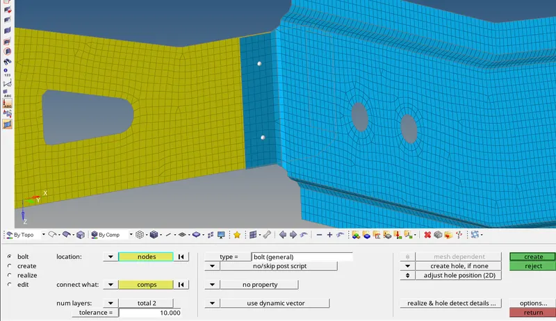
- Select the nodes to which the connection is to be created.
- The tolerance value is to find the elements to attach with in the tolerance range.
- Select the components to be connected.
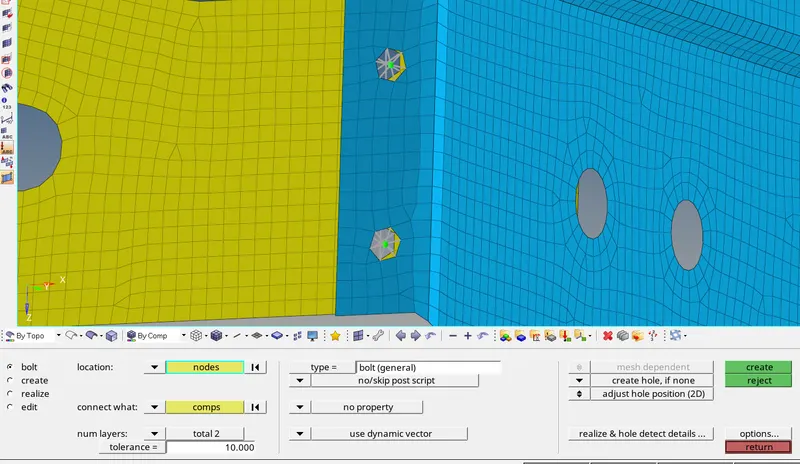
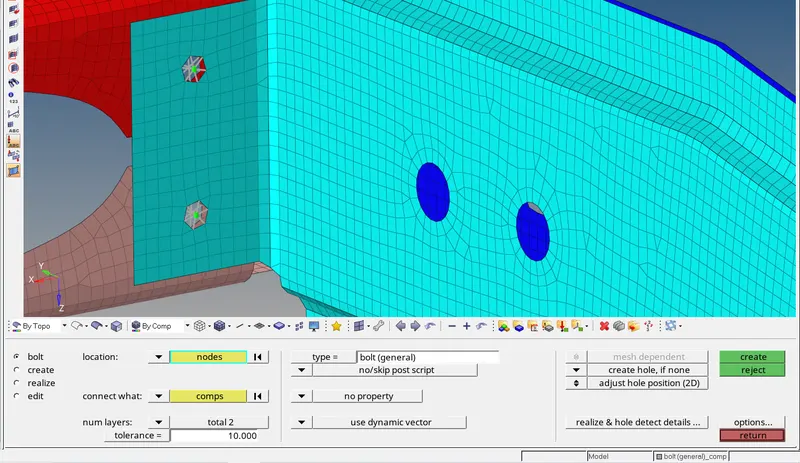
- Bolt connection is created between the required components.
- Rear_truss_2 & Left_Rail_2:- Bolt Connector
Similarly to 5th connection
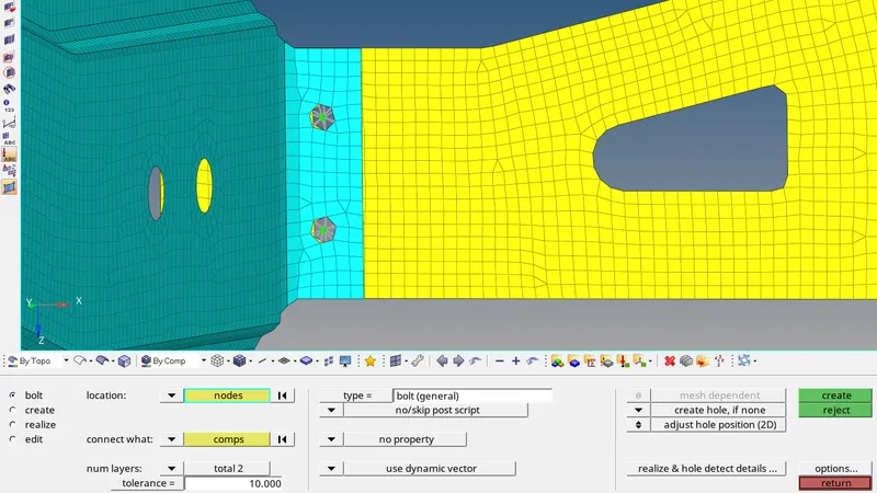
- Bolt connection is created between the required components.
- Right_Rail_1 & Right_Rail_2:- Spot-weld with Rigid Elements

- To create a spot weld connection go to 2D -- > connectors -- > spot.
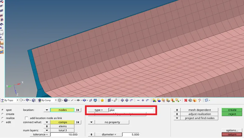
- Click on type to select the type of element to be created.
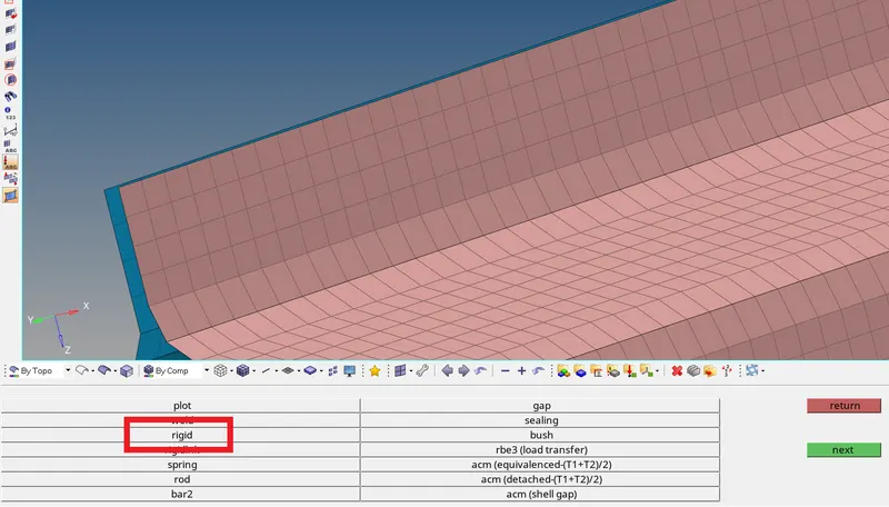
- Click on rigid to select the element type.
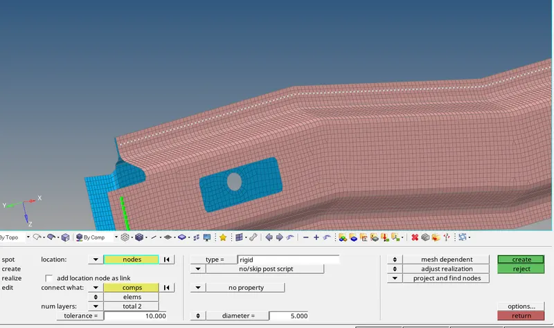
- Select the nodes to which the connection is to be established.
- Select the components to be connected.
- The tolerance value is to find the elements to attach with in the tolerance range.
- Enter the diameter value as required (5mm).
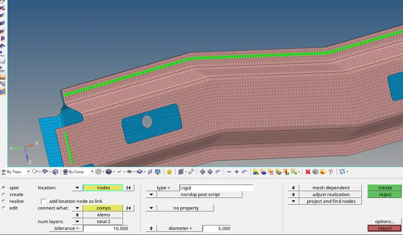
- Spot-weld with Rigid Elements connection is established between the required components.
- Left_Rail_1 & Left_Rail_2:- Spot-weld withSpring Elements
- To create a spot weld connection go to 2D -- > connectors -- > spot.

- Click on type to select the type of element to be created.
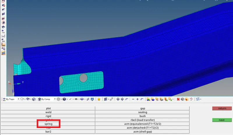
- Click on spring to select the element type.
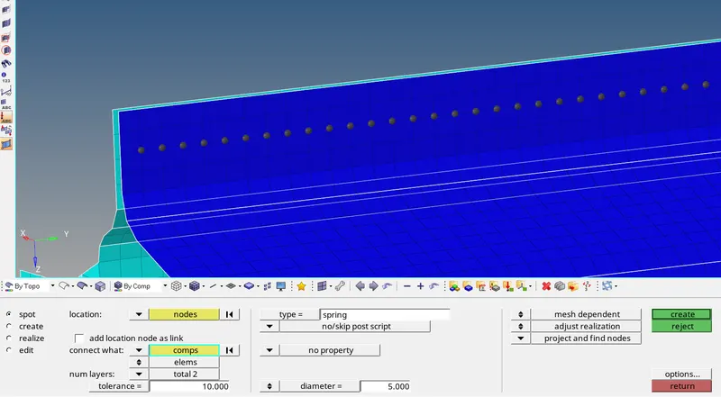
- Select the nodes to which the connection is to be established.
- Select the components to be connected.
- The tolerance value is to find the elements to attach with in the tolerance range.
- Enter the diameter value as required (5mm).
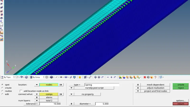
- Spot-weld with Spring Elements connection is established between the required components.
- Rest all the component left Join them with suitable connectors
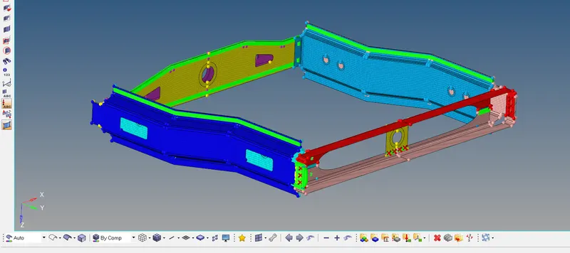
- All connection’s in one image.