Week 6- Challenge
Quality criteria, mesh the component given below and assign thickness:
Target Element Length = 5mm
|
S.N |
Quality Criteria |
Value |
|
1 |
Aspect Ratio |
5 |
|
2 |
Skewness |
45 |
|
3 |
Warping |
15 |
|
4 |
Taper |
0.5 |
|
5 |
Min. Length |
2mm |
|
6 |
Max. Length |
8mm |
|
7 |
Min angle Quad |
45 |
|
8 |
Max angle Quad |
135 |
|
9 |
Min angle Tria |
20 |
|
10 |
Max angle Tria |
120 |
|
10 |
Tria % |
10 |
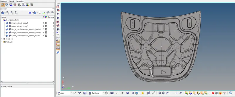
Importing the model.
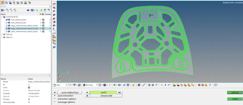
Creation of Missing Surfaces:
Geom -- > Surfaces -- > Splines/Fillers
Follow the same for creating all the mid-surfaces.
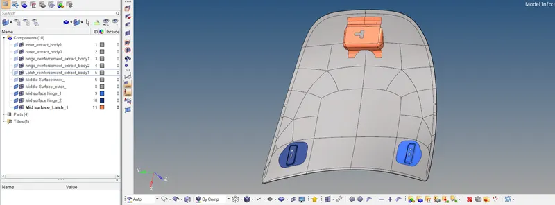
Now start meshing individual mid-surfaces:
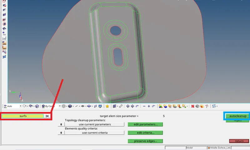
Cleanup: Geom -- > autocleanup
After creating all missing surfaces, deleting all extra surfaces and ready the geometry for cleanup.
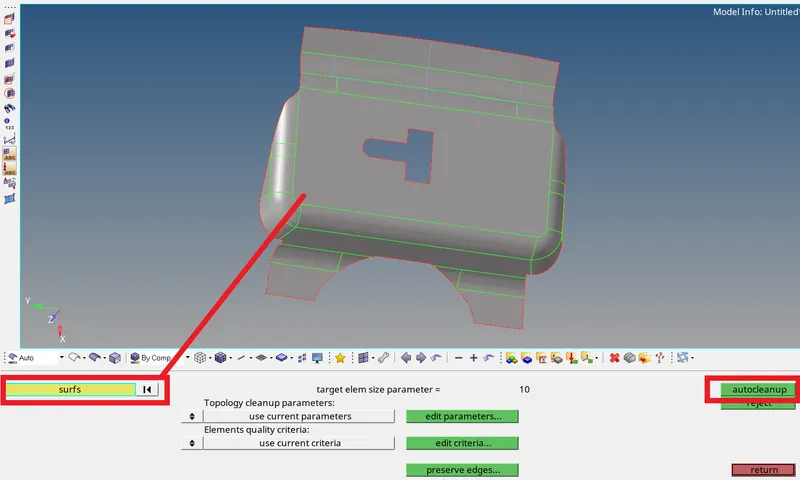
- In the edit criteria, we can edit all the criteria’s like element size and rest as per our requirement.
- After setting all the Criteria and parameters selection of all the surfaces is done.
- And finally, click autocleanup.
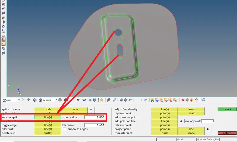
Creation of Washer Split: : Geom -- > quickedit
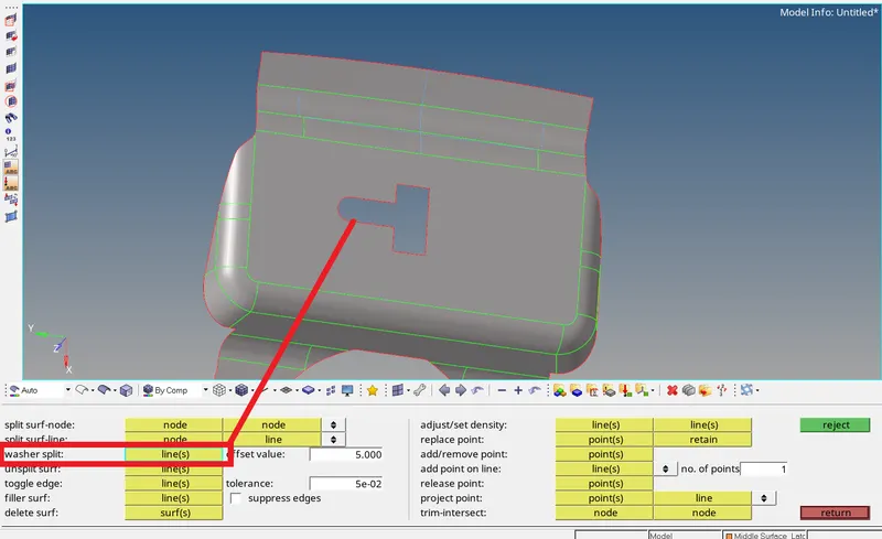
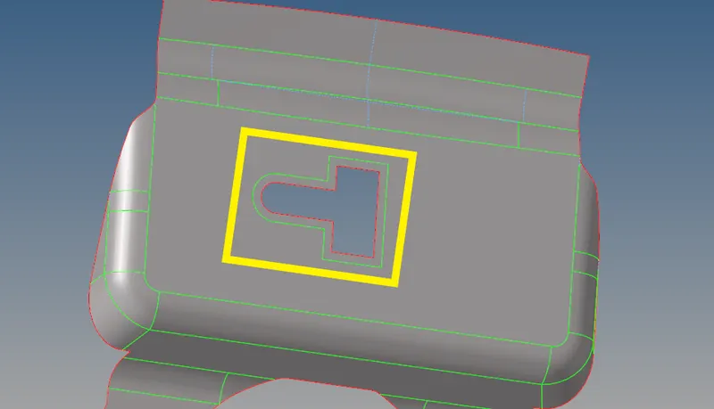
- Cleanup surface is created.
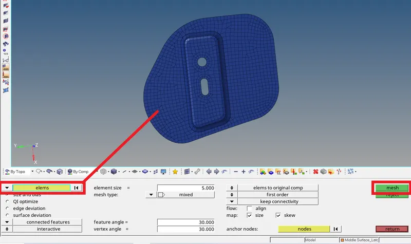
Creation of Mesh: 2D -- > automesh

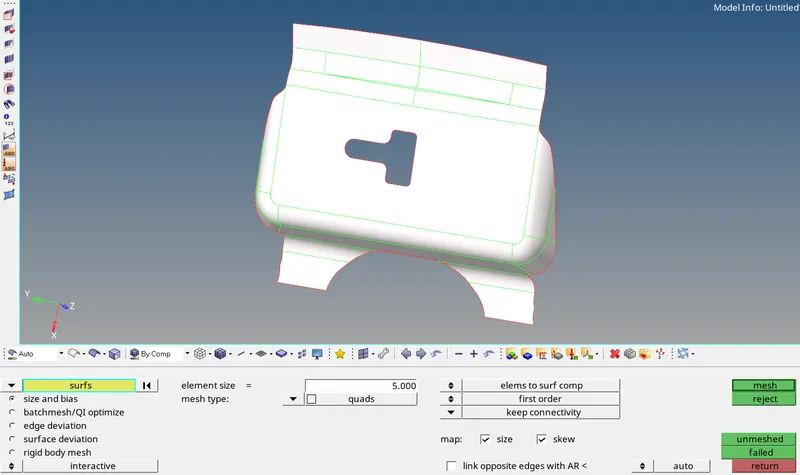
- Enter the required mesh dimension(5).
- Selection of the surfaces to mesh and press mesh.
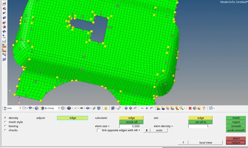
- Need to re-mesh locally if required.
- Or we can also mesh optimize.
Qualityindex : 2D -- > qualityindex

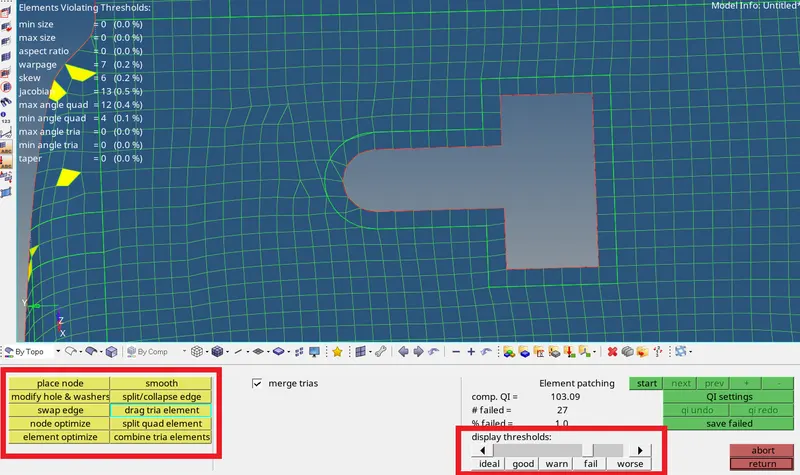
- Display thresholds shows the elements in different thresholds, which are from ideal elements to worse elements.
- The optimizing tools are used to change the elements from worse to ideal(if possible).
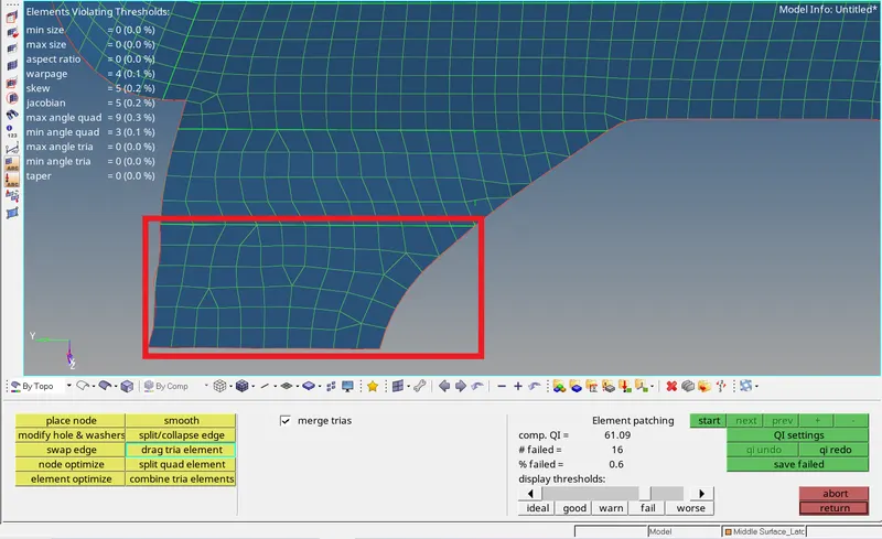
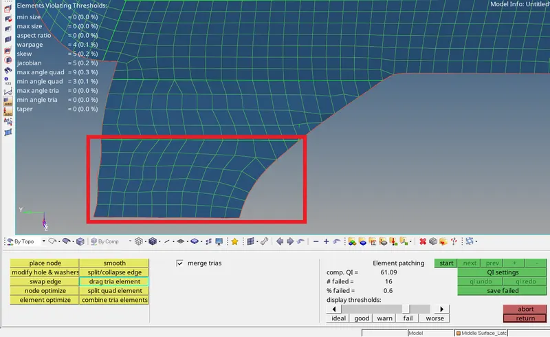
- The difference the above two images are done with the optimizing tools to modify the existing mesh to a good mesh.
Alignment of Nodes: Geom -- > Node edit -- > align node (F7)
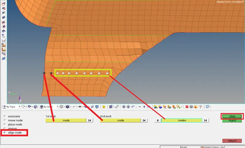
- The align node is used to adjust the nodes in a line with the selection of 1st end and 2nd end nodes which form the line and the rest nodes selected will shift to this line to follow.
After re-meshing , optimizing and aligning every surface of the Latch, we need to check elements for given Quality Criteria. After checking the elements if they don’t follow the quality criteria those elements are to be remeshed, optimized or recreated as required.
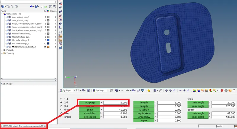
Check Elements for Quality : Tool -- > check elems (F10)

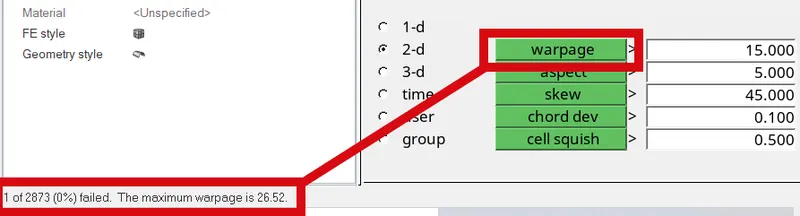
- On left bottom corner of the window, the number of failed elements are shown.
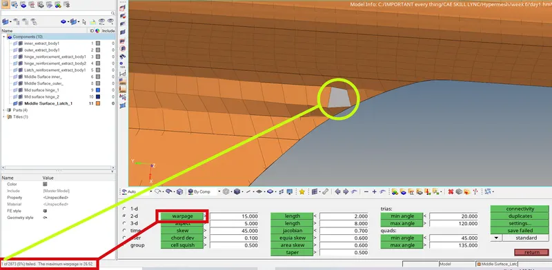
- The failed elements are also highlighted as shown in the above image.
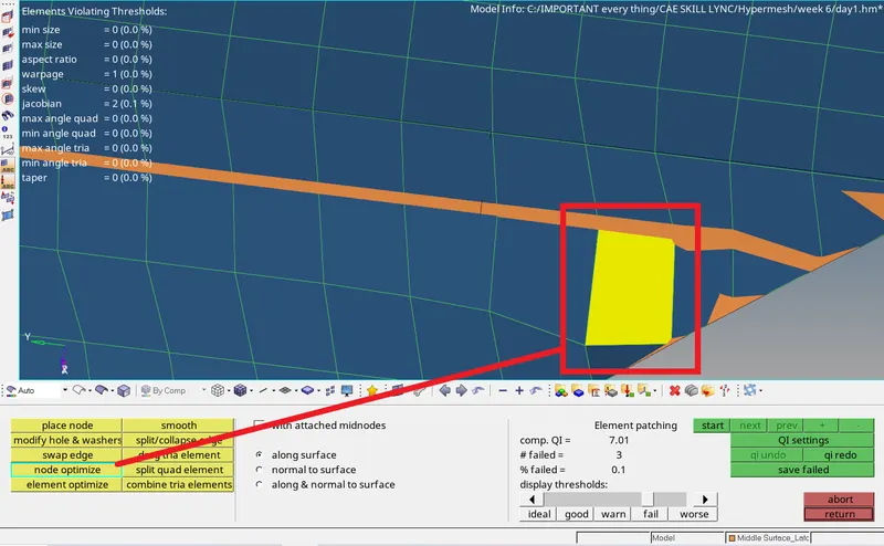
- The node optimize eliminates the general defecates of the mesh.
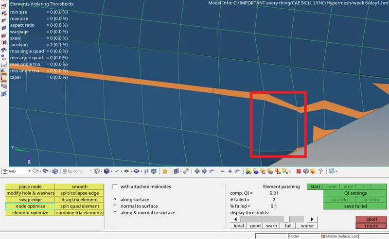
- The element is corrected for the quality criteria.
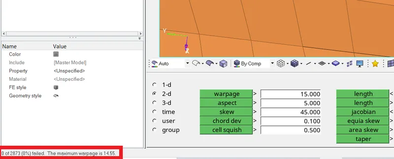
- Edit until the failed elements are Zero. The failed elements for warpage ae zero.
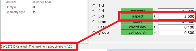
- We can see that the failed elements for aspect ratio are Zero. Go to next quality criteria.
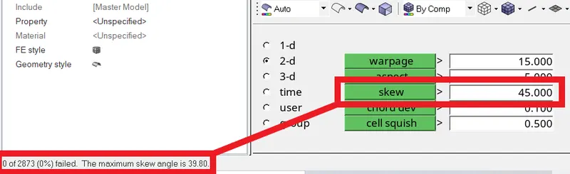
- We can see that the failed elements for skew angle are also Zero. Go to next quality criteria.

- We can see that the failed elements for min length are also Zero. Go to next quality criteria.
- If any failed elements are present they can be re-meshed, optimize.
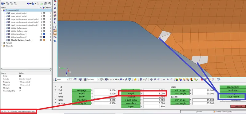
- There are 4 failed elements for maximum length as shown.
- The save failed is used to save the failed elements, for retrieving then for the cleanup without any confusion that which are the failed elements.
Masking the elements: Tool -- > mask (F5)

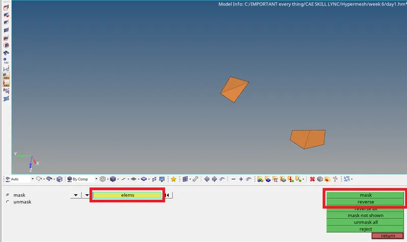
- The failed element are retrieved from elems and they are masked and reversed. So that only the failed elements are in display.
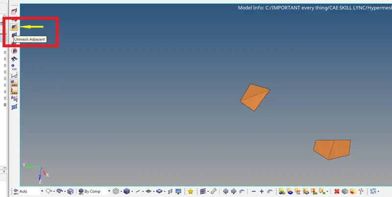
- The icon marked is the Unmask Adjacent icon which is used to display the adjacent elements of our failed elements for the next cleanup.
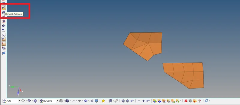
- The adjacent elements are displayed.
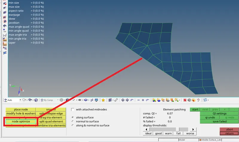
- The nodes are optimized and failed elements are eliminated.

- We can see that the failed elements for min angle for trias are Zero. Go to next quality criteria.

- We can see that the failed elements for max angle for trias are also Zero. Go to next quality criteria.

- We can see that the failed elements for min angle for quads are Zero. Go to next quality criteria.

- We can see that the failed elements for max angle for quads are Zero.
Following the same steps for all the other surface parts for the creation of Mesh and cleanup of Mesh.








For the outer extract of the hood:
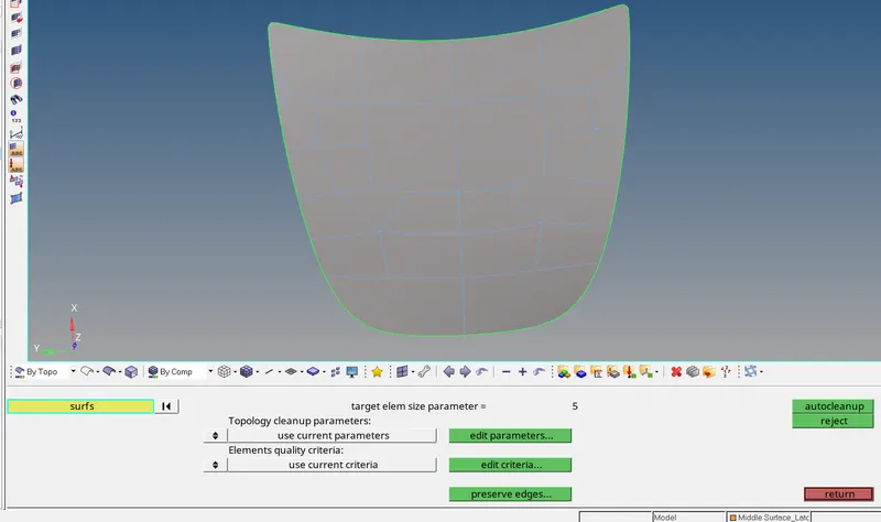
- After the autocleanup of the outer extract as all the surfaces are combined to create a single surface as shown in the figure.
- As for the cleanup the mesh it difficult to have a clean mesh for one big surface, this surface is parted into sections for the ease of cleanup creation.
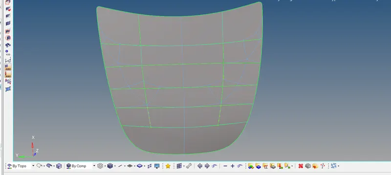
- The lines are created with the help of nodes and the lines are projected onto the surface with Project option from Tool panel.
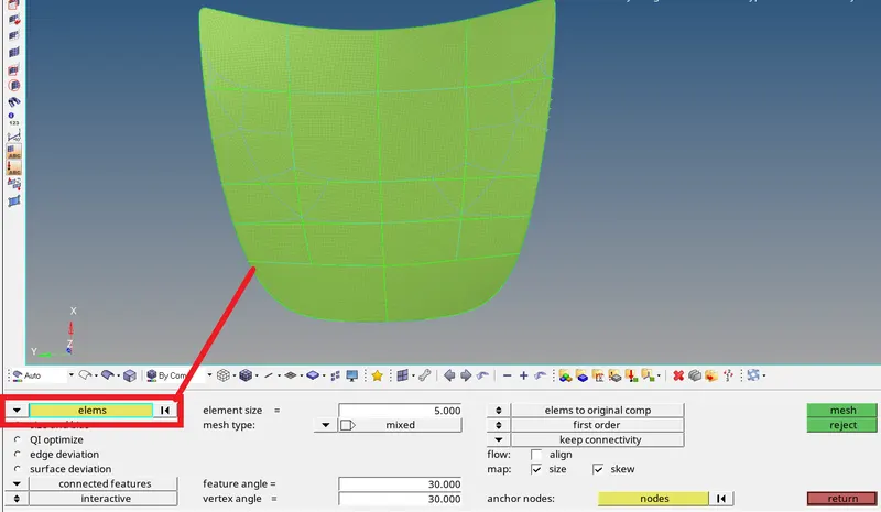
- Following the same steps for all the other surface parts for the creation of Mesh and cleanup of Mesh.
- And remesh and optimize for the cleanup of the failed elements of the outer extract until it satisfies all the quality criteria.
For the inner extract of the hood:
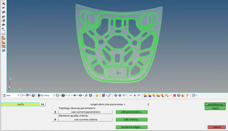
- Creation of the mid-surface of the hood.
- After that Autocleanup of the mid-surface of the inner extract of hood.
- The edit criteria is filled as required and the autocleanup is done.
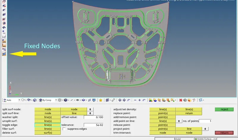
- As the autocleanup doesn’t give the completely ready geometry cleanup it is done manually for all the portions which require manual cleanup of geometry.
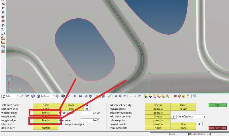
- In the above image the washer split is created and the unwanted edges are toggled or suppressed.
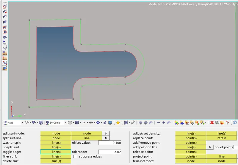
- Washer split is created as required.
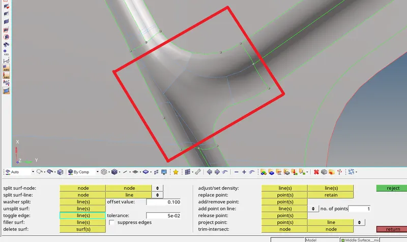
- All the edges and non-important edges are toggled as they can cause problem for the mesh.
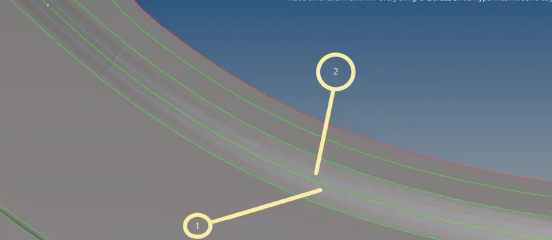
- In place of the edges 1 and 2 mid line is created with line edit -- > mid line option, so that mesh size lesser that minimum value are not created.
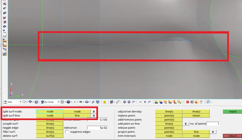
- As boxed in the above image there is an error in the surface, so autocleanup couldn’t create any edge there.
- The edge can be created in manually with the tools split surf-node (which connects node to next node and creating an edge.
- Or Split surf-line in which node and line are selected for the creation of edge between node and the selected line.
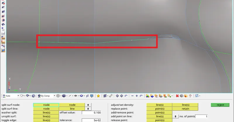
- Creation of edge by node to node.
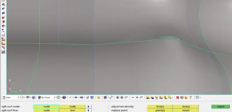
- Completing the edge by node to line option.
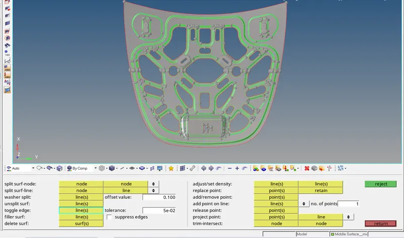
- All the required edits are done and the geometry cleanup is done and the Geometry is ready for meshing.
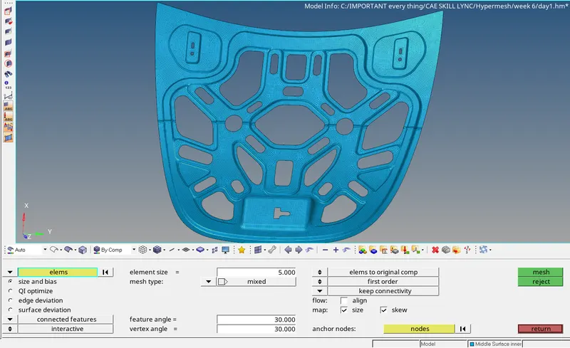
- The element size and mesh requirements are entered and the geometry cleaned-up surface is meshed.
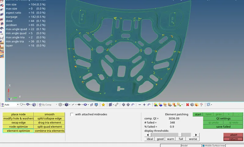
- Looking at the mesh in the 2d -- > qualityindex we can see that there are many mesh elements that are to be remeshed or optimized as required.
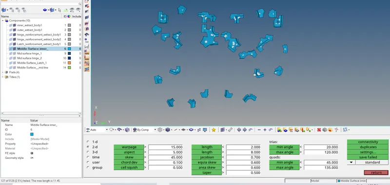
- All the failed elements of max length are saved and retrieved in the mask(F5) and masked and reversed.
- And the Unmasked adjacent is used to display the adjacent elements of the failed elements.
- One by one all the failed portions are re-meshed and element optimized and all the failed elements are converted to quality pass elements.
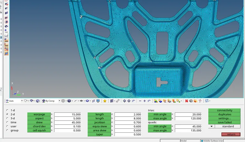
- Similar to the failed elements of max length all the failed elements of warpage, aspect ratio, skewness, min length, taper, min and max angles of trias and quads are found and are corrected one by one.
- And finally all the failed elements for the quality criteria are brought to Zero.
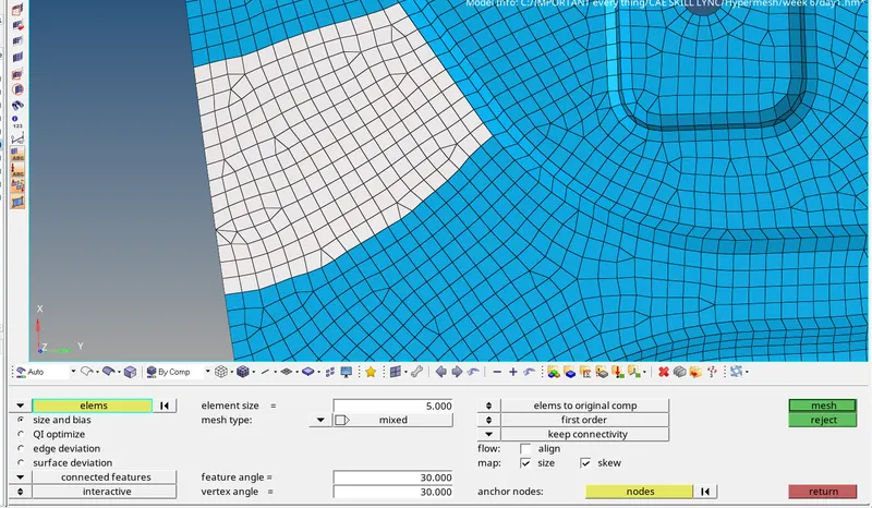
- As we can see that few elements that can be cleaned up further are re-meshed for good pattern of mesh.
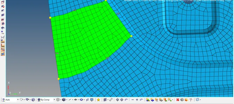
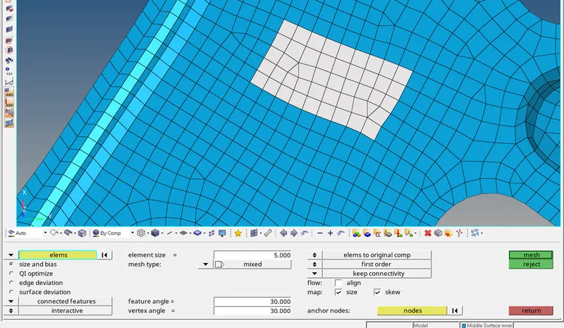
- Where ever we find the opposite tries a boxed re-mesh can be done to eliminate them.
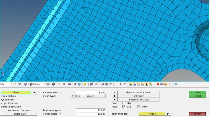
- The opposite tries are eliminated.
After all the mesh cleanups and the entire model is brought to zero failure elements.
As given assigning the Material and Thickness to all the surfaces:
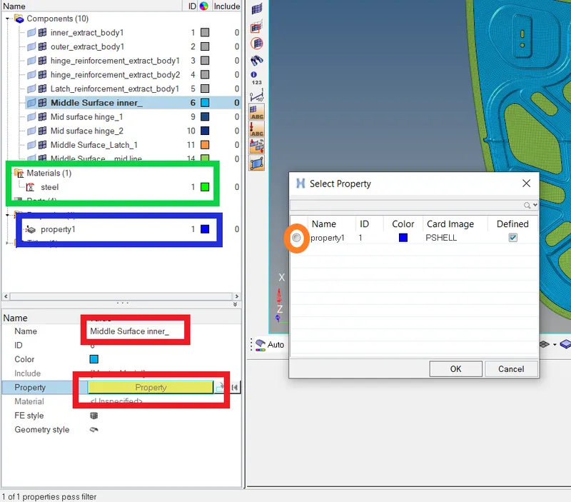
- Creation of the Material and Property in Model View.
- Entering the thickness and other required values in the property1.
- And finally assigning both material(steel) and property1 for all the surfaces.
Check Mode:
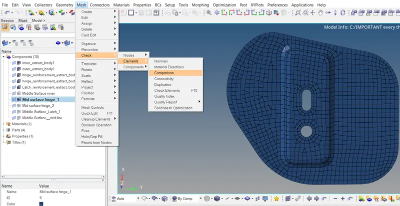
- For checking did the mesh correctly captured the surface this option in the above image is used.
- Mesh -- > Check -- > Elements -- > comparison
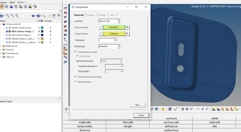
- Elements are to be compared are selected and the surface associated with that mesh element is selected and press Run.
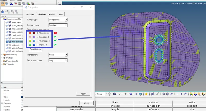
- The color coed on the comparison panel shows that the red and maroon color elements are not acceptable and are to be modified by projecting the elements to surface.
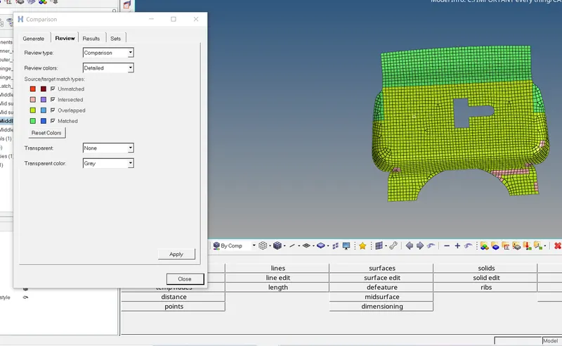
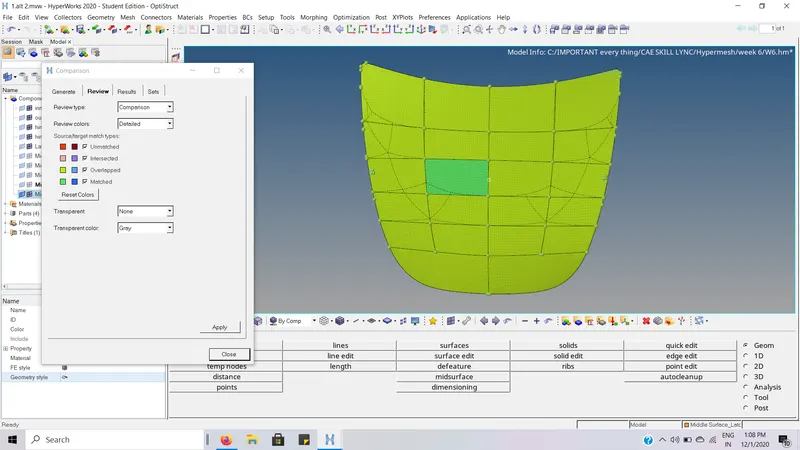
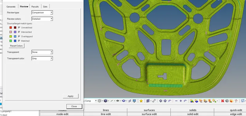
- As we can see that all the elements of the above image are acceptable the elements are in correct form.
Similarly :
Normals Check:
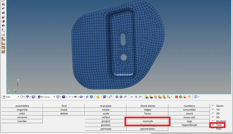
- The normals check is present in Tool -- > normals
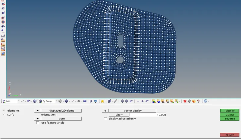
- All the normals of the surface are to be in the same direction.
- As we can see that in the above model all the normals are in the same direction, the surface is good.
Similarly :
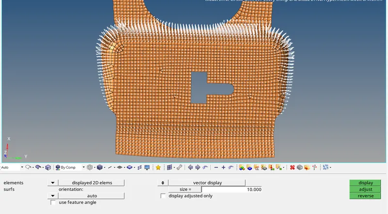
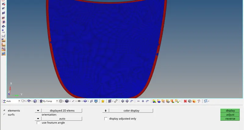
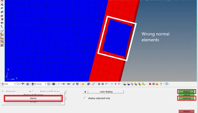
- We can see there are wrong normal elements present.
- These elements are selected and reversed.
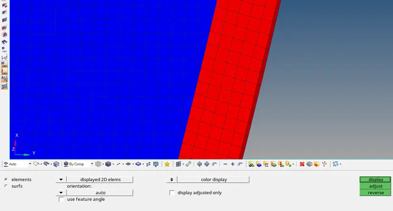
- The wrong normal elements are corrected.
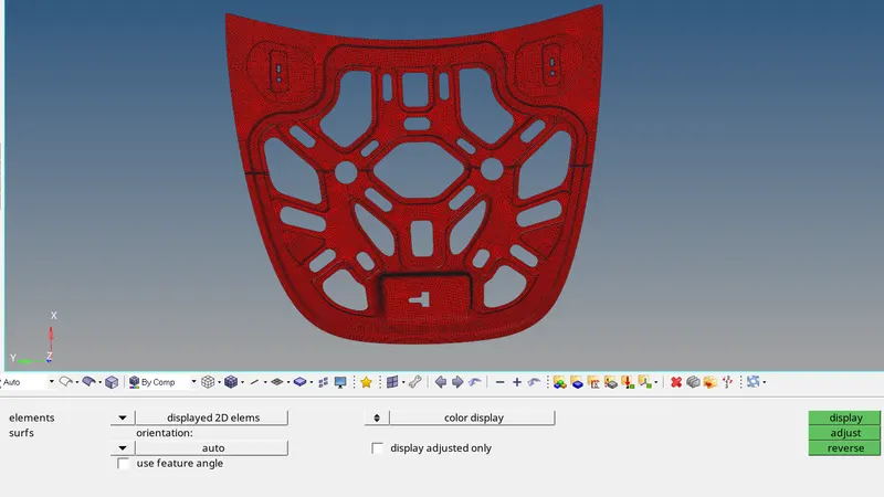
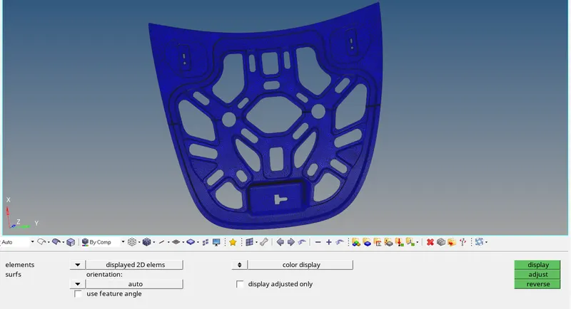
- All the elements are incorrect normal direction.