Assignment 3-2D Element Formulation Challenge
Questions:
Comparison of results with base simulation and improved shell element properties
1.Using the crash beam file from the previous assignment, change the run time to 55 ms.
- 2. Change the number of animation steps during simulation to a minimum of 25 and maximum of 60.
- Run the base simulation without any modification to element properties.
- 4. At the end of the simulation, do the energy error and mass error checks and determine whether results would be acceptable.
- 5. If acceptable, Plot rigid wall forces, internal energy, hourglass energy, contact energy, total energy of the simulations.
- 6. Change all the shell elements properties to recommended properties, save this as separate, rad files and run the simulation.
- 7. Follow steps 5 and 6.
- 8. Create a brief report comparing all the results from steps 5 and 6 for both simulations.
- 9. Comment whether there is any change in the results and why there is any change in the result
Import .rad File:
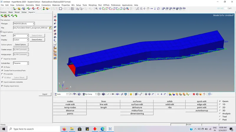
Change the run time to 55 ms:
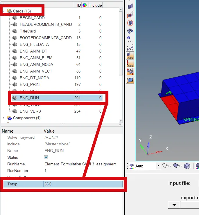
- The run time is set to 55ms.
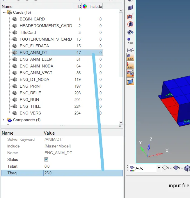
- The number of animation steps during simulation is set to 25.
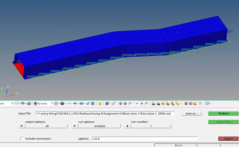
- Go to Analysis -- >
- Select the file path as required.
- Select the export options to all.
- Usage of threads in CPU as required, here it is –nt 4.
- And click on Radioss for the simulation without any modification to element properties.
Energy error and Mass error:
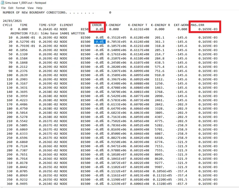
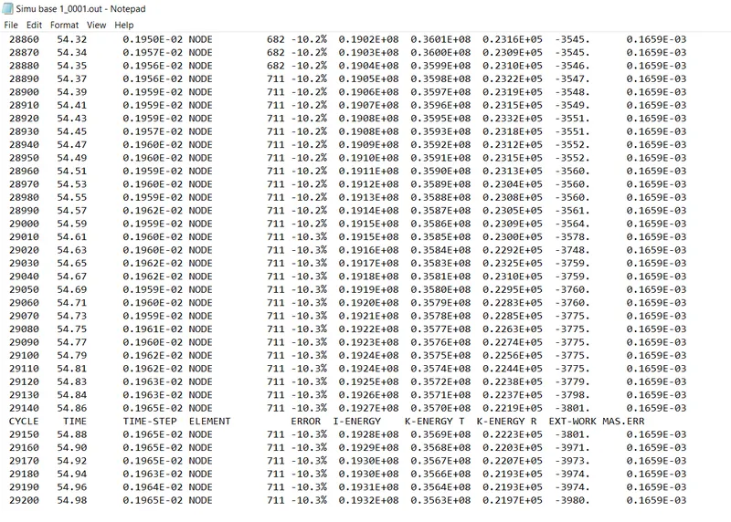
- As the energy error was negative throughout the simulation it is acceptable.
- And throughout the simulation the mass error didn’t change large locally and stayed constant throughout the simulation it is acceptable.
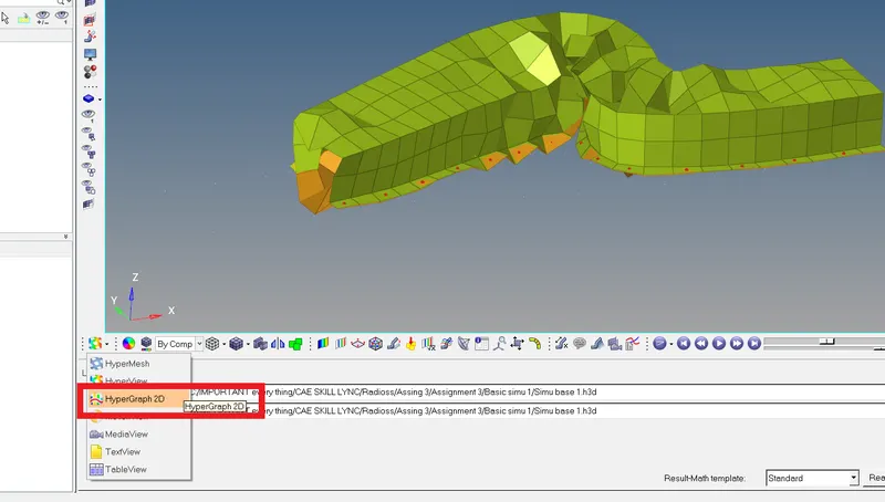
- After the simulation goes to HyperGraph 2D.
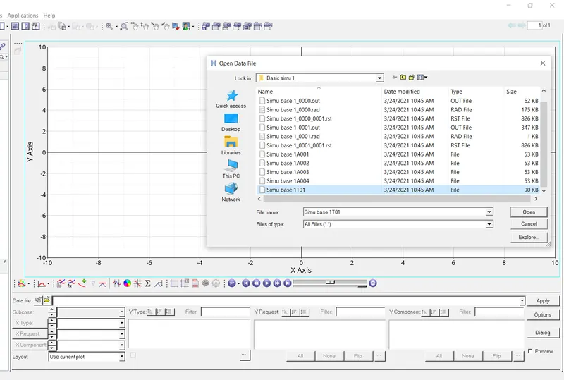
- Open the T01 file which is the only acceptable format of HyperGraph 2D to plot the required graphs.
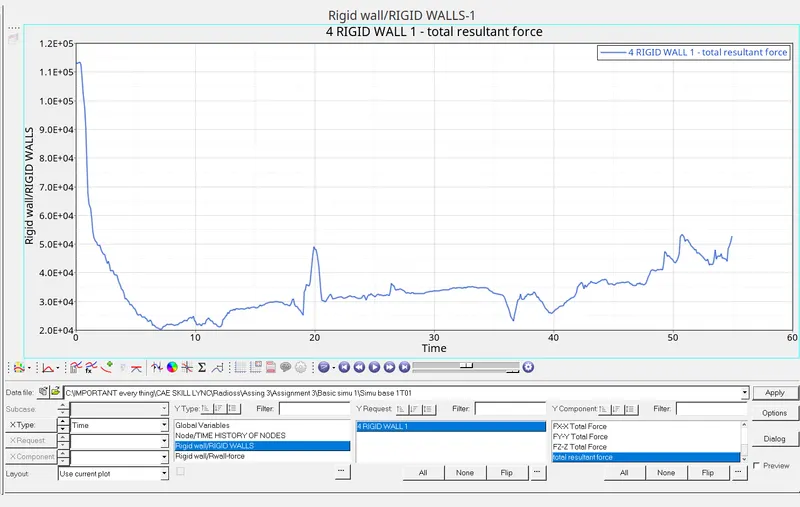
- Rigid wall forces of total resultant is plotted.
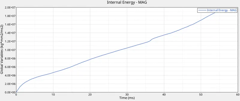
- Internal Energy in the simulation is plotted.
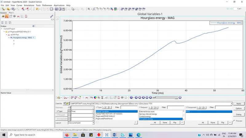
- Hourglass energy in the simulation is plotted.
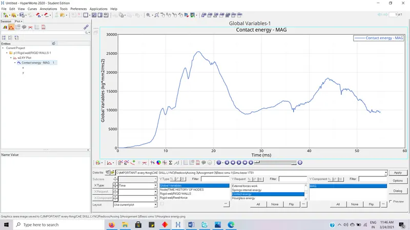
- Contact energy in the simulation is plotted.
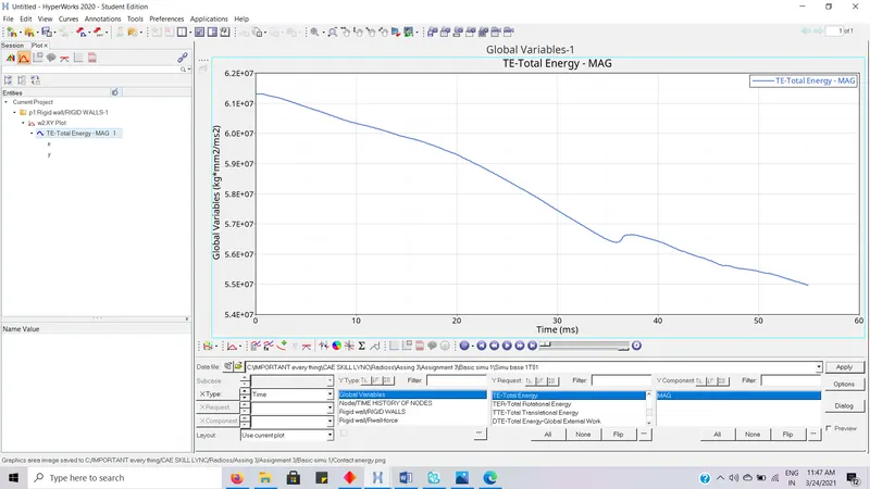
- Total Energy in the simulation is plotted.
Change all the shell elements properties to recommended properties, save this as separate, rad files and run the simulation:
Import .rad File:
Change the run time to 55 ms:
- The run time is set to 55ms.
- The number of animation steps during simulation is set to 25.
Recommended properties:
|
Parameters |
|
Comment |
|
Ishell =24 |
|
QEPH 4 nodes shells are best combination of cost and accuracy. |
|
Ismstr=2 |
|
Full geometric nonlinearities (default)with possible small strain formulation activation in RADIOSS Engine. |
|
Ish3n=2 |
|
Standard 3 noded shell (C0)with modification for large rotation(default) |
|
N=5 |
|
Number of integration points set to 5 for accuracy bending. |
|
Ithick=1 |
|
Thickness change is taken into account for accuracy. |
|
Iplas=1 |
|
Iterative plasticity for good accuracy. |
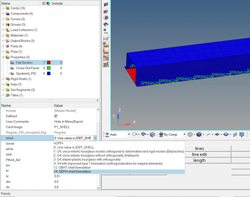
- Ishell is set to 24.
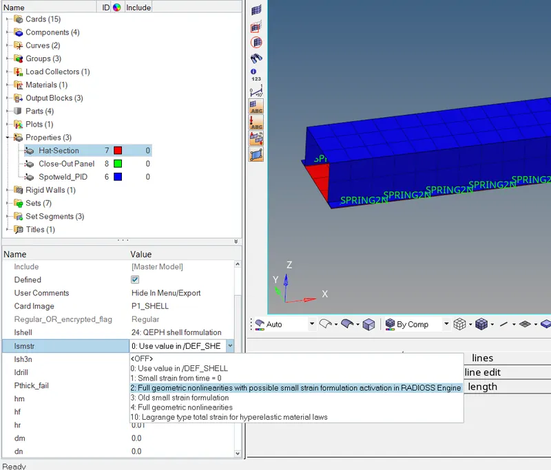
- Ismstr is set to 2.
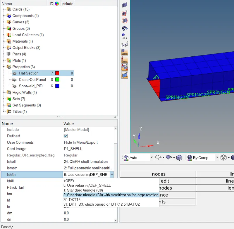
- Ish3n is set to 2.
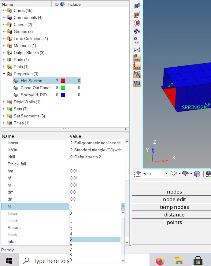
- N is set 5 (Number of integration points set to 5 for accuracy bending.)
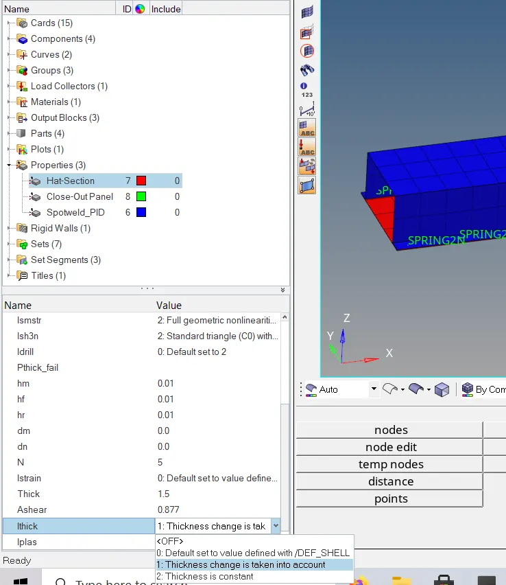
- Ithick is set to 1 Thickness change is taken into account for accuracy.
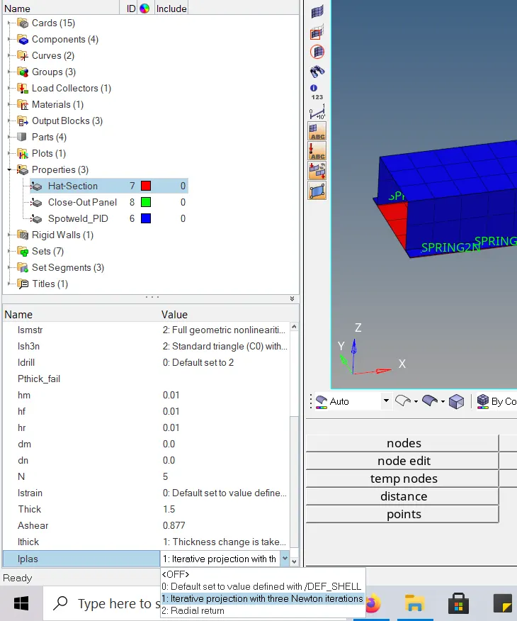
- Iplas is set to 1 for Iterative plasticity for good accuracy.
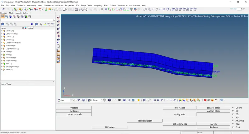
- As of now all the recommended properties are set go to Analysis -- > Radioss to carry the simulation.
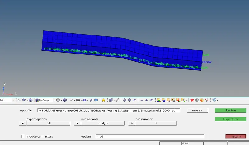
- Select the file path as required.
- Select the export options to all.
- Usage of threads in CPU as required, here it is –nt 4.
- And click on Radioss for the simulation without any modification to element properties.
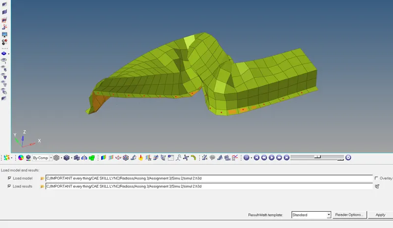
- Simulation is done and the simulation with recommended properties is natural compared to the 1st
Energy error and Mass error:
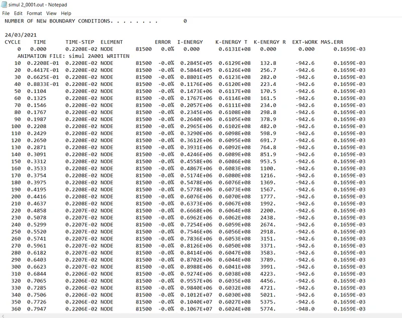
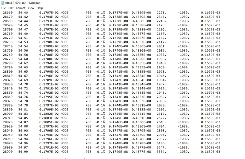
- As the energy error was negative throughout the simulation it is acceptable.
- And throughout the simulation, the mass error didn’t change large locally and stayed constant throughout the simulation, which is acceptable.
- After the simulation go to HyperGraph 2D.
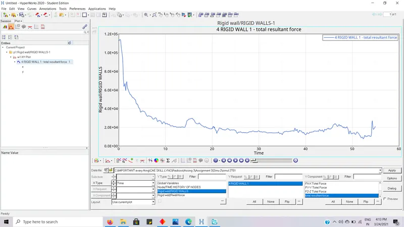
- Rigid wall forces of total resultant is plotted.
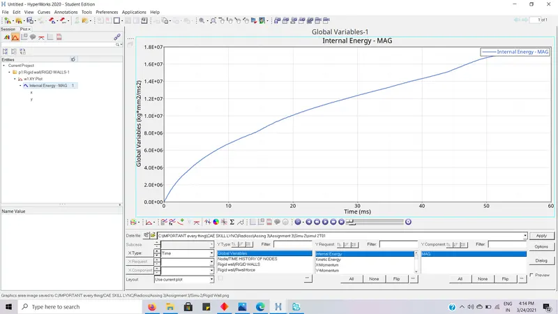
- Internal Energy in the simulation is plotted.
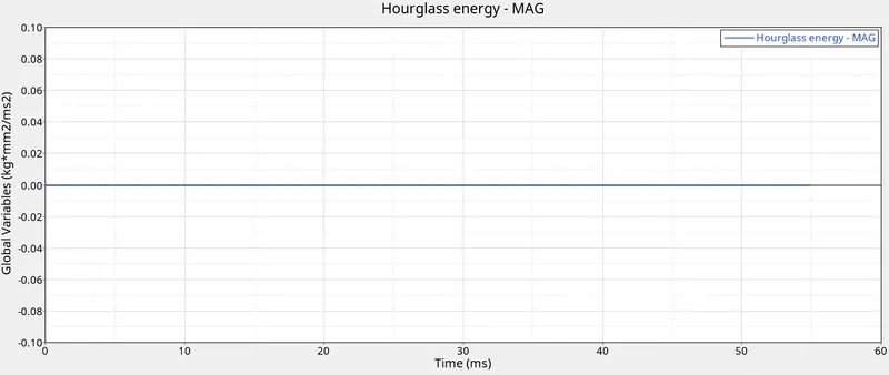
- Hourglass energy in the simulation is plotted.
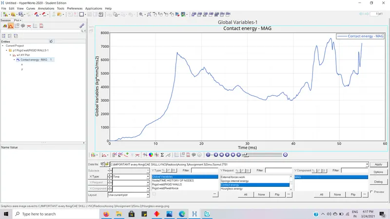
- Contact energy in the simulation is plotted.
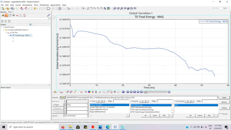
- Total Energy in the simulation is plotted.
Comparison:
Note:
- For all plots below Red curves are Simulation results with Recommended Properties.
- And Blue curves are Simulation results without any modification to element properties.
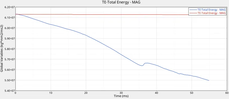
- We can see that with recommended properties the total energy in the system stayed stable and constant and in first simulation are total energy decreased highly as integrations points were not set and Iterative plasticity is not accuracy.
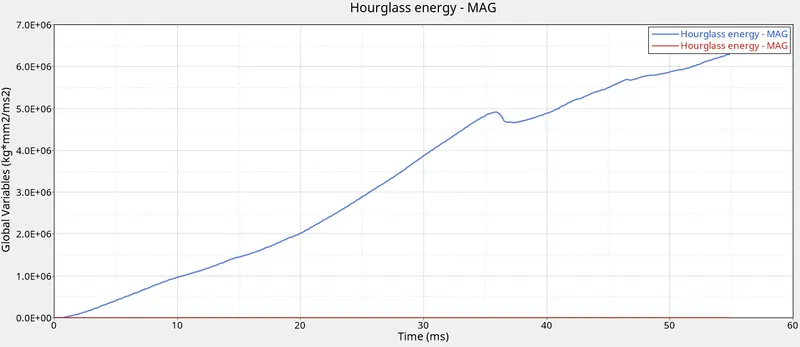
- We can observe that the Hourglass energy in the 2nd simulation is constantly stayed zero throughout the simulation and in 1st simulation we can observe that there is a large change in Hourglass energy.
To understand this change we need to know what is Hourglass energy.
This is a non-physical phenomenon (i.e. does not occur in real life structures) that occurs due to reduced stiffness of the elements.
Basically, it occurs due to the unintegrated element subjected to bending loads.
There is no force or stress energy but deformation still occurs due to this hourglass effect.
To counterbalance this effort excess forces can be added and nullify that.
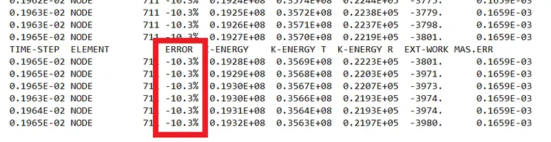
- In this 1st simulation the energy error of -10% is the cause for the abrupt increase in Hourglass energy in the above plot.
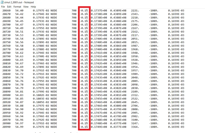
- In this 2nd simulation the energy error stayed contact throughout the simulation about -0.1% which was the reason the Hourglass energy in the above plot stayed constant.
This energy error and Hourglass effects was basically controlled by the selection of the
|
Ishell =24 |
|
QEPH 4 nodes shells are best combination of cost and accuracy. |
Which is the fully integrated upon elements which removed the unintegrated elements which are present in the first simulation.