Assignment 6-Frontal Crash Simulation Challenge
Frontal crash-BIW
- Check unit system and either follow[Mg mm s] or [Kg mm ms].
- Create appropriate interface ,friction 0.2 and recommended parameters.
- Make sure of no penetrations and intersection.
- Correct rigid bodies if any issues.
- Create rigid wall with friction 0.1.
- Compare the model weight with the full scale 300k nodes model and use added masses to reach target weight 700kg while getting CG about the required range.
- Initial velocity 35 mph.
- Use model checker to ensure good quality.
- Time-step :0.5 to 0.1 microseconds.
- Run 80 ms.
Output requests:
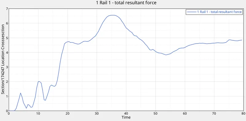
- Sectional force in the rails at location of indicated node 174247.
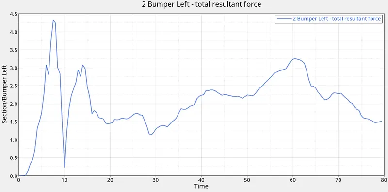
- Axial force received on the rails from bumper.
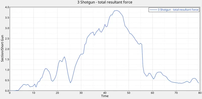
- Shotgun cross sectional forces.
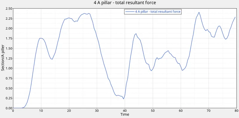
- A pillar cross section.
- Acceleration curve received on the accelerometer at base of B pillar (on B pillar rocker).
- Intrusions on the dash wall 66695,66244.
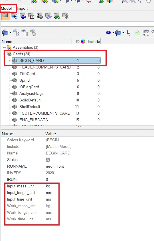
Objective 1: Check unit system and either follow[Mg mm s] or [Kg mm ms].
Checking Unit system of model:
Model Browser >> Cards >> Begin_Card
Objective 2: Create appropriate interface ,friction 0.2 and recommended parameters.
Model Browser >> Groups >> Create group >> (name)
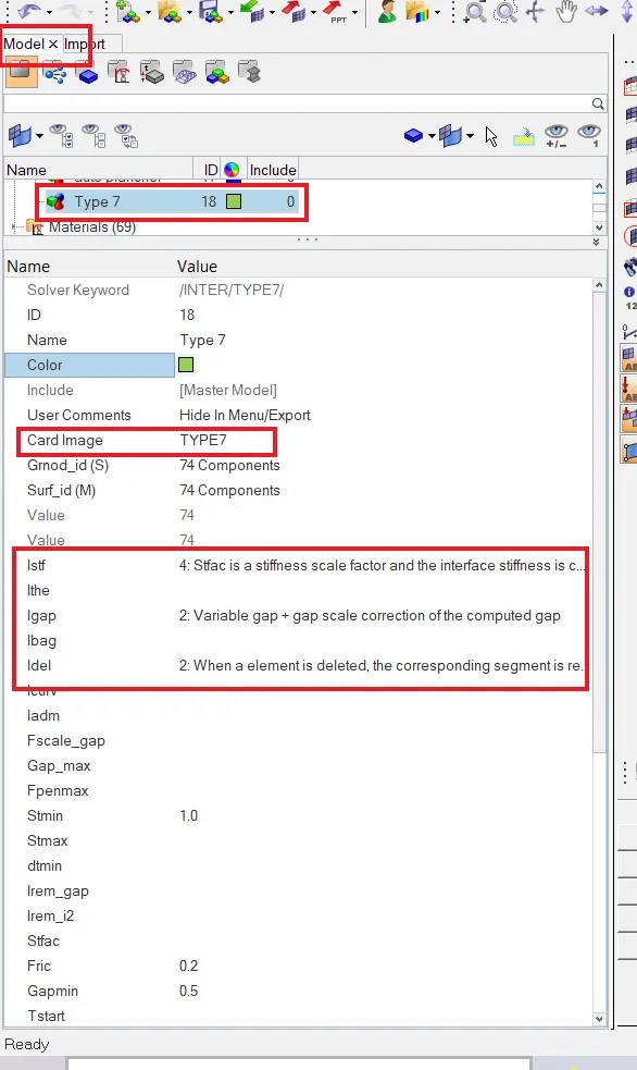
- The friction(Fric) is set to 0.2 as given.
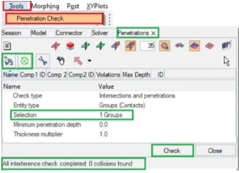
Objective 3: Make sure of no penetrations and intersection.
Menu >> Tools >> Penetration Check
Objective 4: Create rigid wall with friction 0.1.
Menu >> Tools >> Create Card >> RWALL >> PLANE
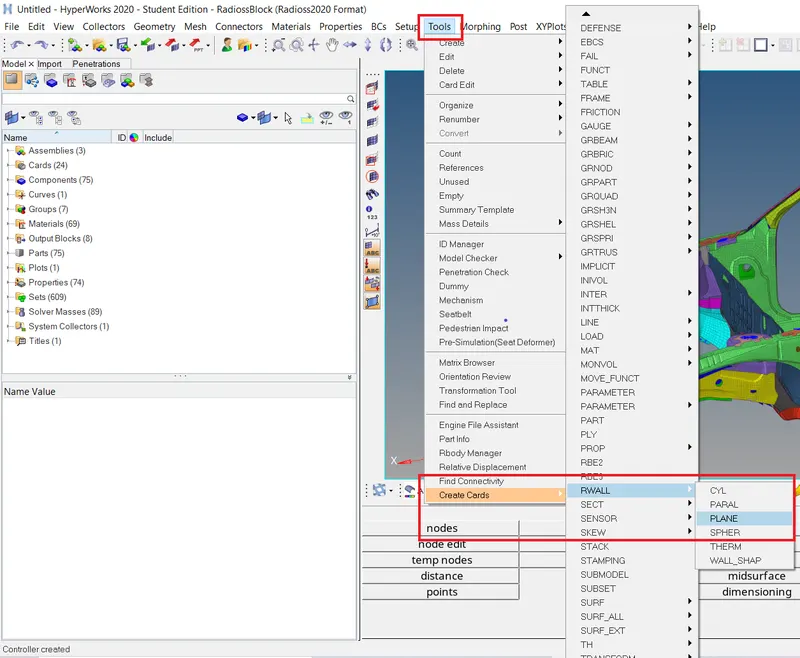
>> Place the RWALL at required location.
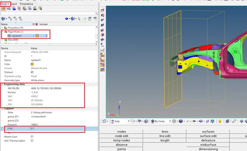
- Location is set and friction is also set to 0.1 as required.
Objective 5: Adding masses to reach target weight 700kg while getting CG about the required range.
>> Check Mass summary to see mass, COG.
Menu >> Tools >> Mass Details >> Mass, Cog and inertia
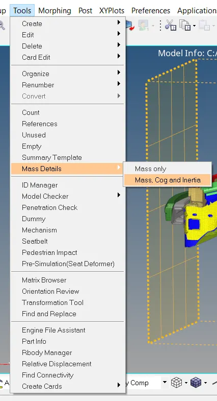
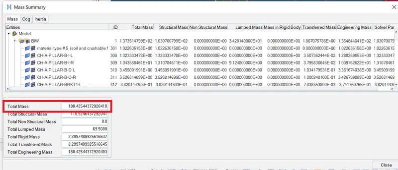
- We see that the mass is less than 700 kg.
>> GRNODE is created to add mass
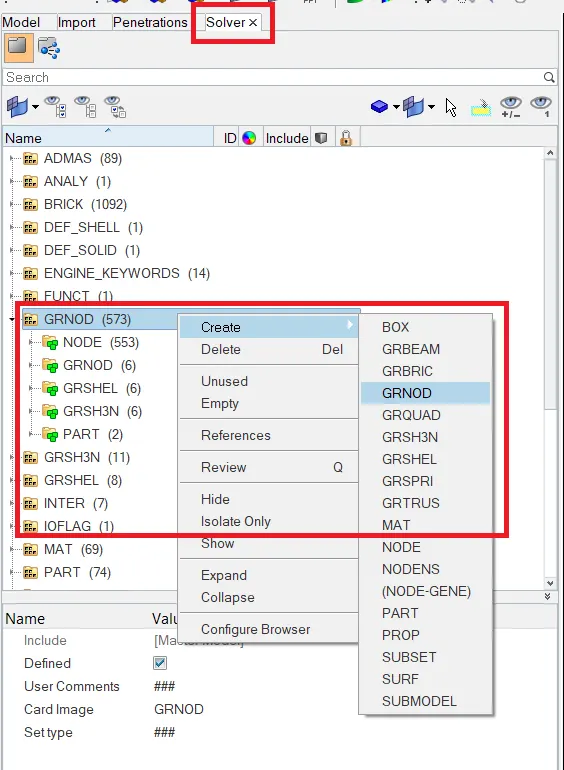
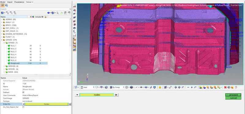
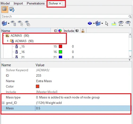
- On the selected nodes point mass of 0.5 is added for all the nodes.
Final Mass and COG check:
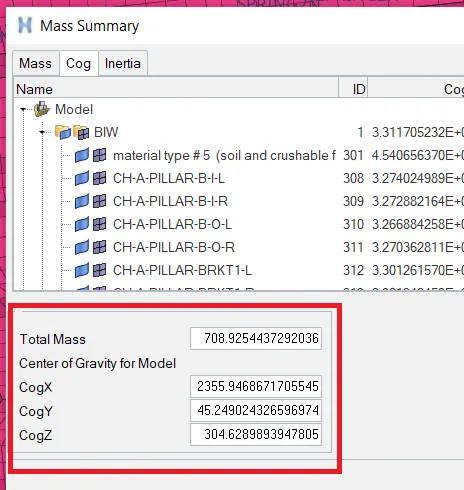
- As required the mass and cog is brought to necessary requirements.
Objective 6: Adding Initial velocity 35 mph.
Solver >> Create >> Boundary Condition >> IMIVEL
- IMIVEL is created.
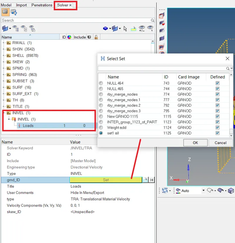
- All the nodes are taken in a set and assigned to INIVEL.
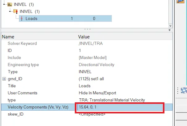
- 30 Mph is converted to mm/ms and assigned.
Objective 7: Time-step :0.5 to 0.1 microseconds.
Model >> Cards >> ENG_ANIM_DT
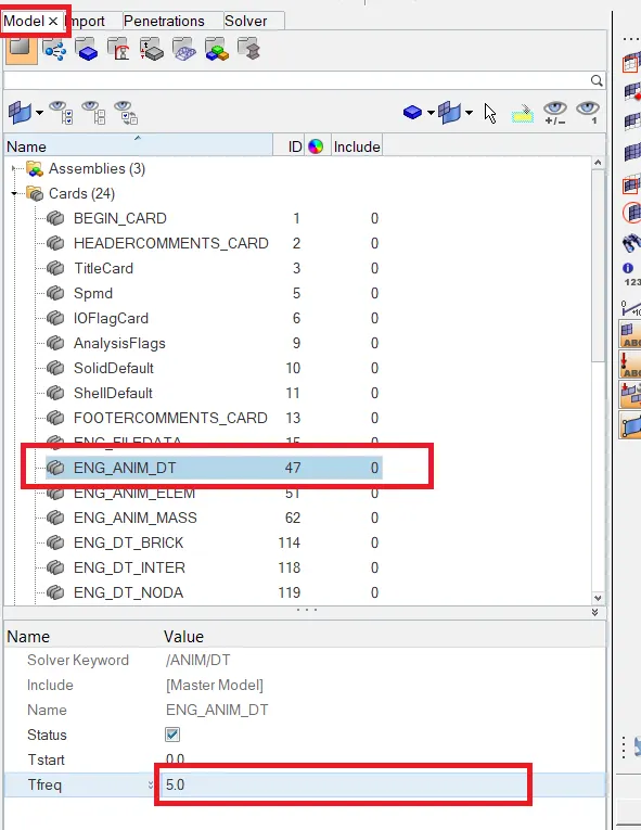
- Time step set to 0.5.
Objective 8: Run Time to 80 ms.
Model >> ENG_RUN >
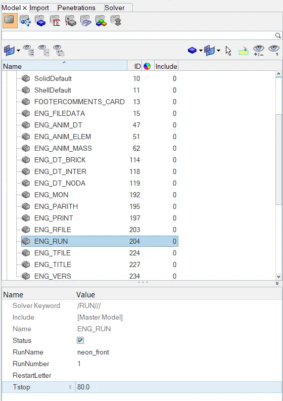
- Run time is set to 80ms.
Output requests:
Request 1: Sectional force in the rails at location of indicated node 174247.
STEP 1: Find node 174247:
Tools >> numbers >> by in >> type node number >> display on
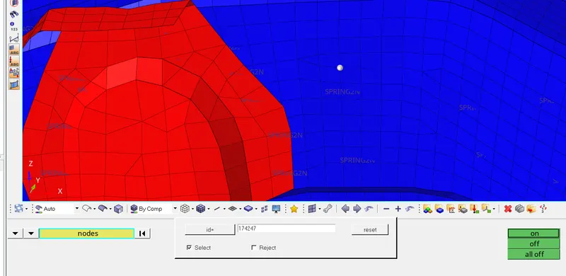
STEP 2: Creating FRAME >> MOV
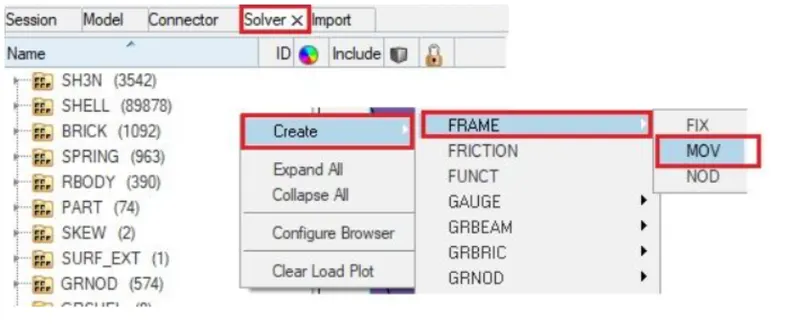
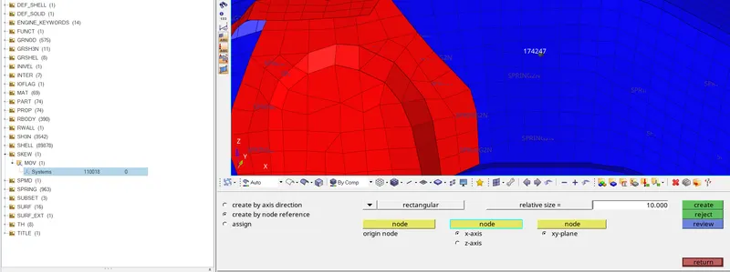
- Selection of nodes is done to create the MOV system
STEP 3: Creating SECT >> SECT
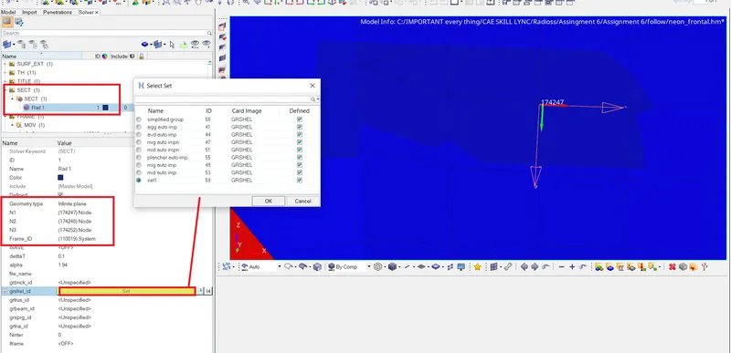
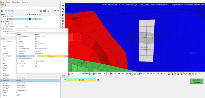
- These elements are selected for the force passing through the section.
STEP 4: Giving Output Request to Model Browser.
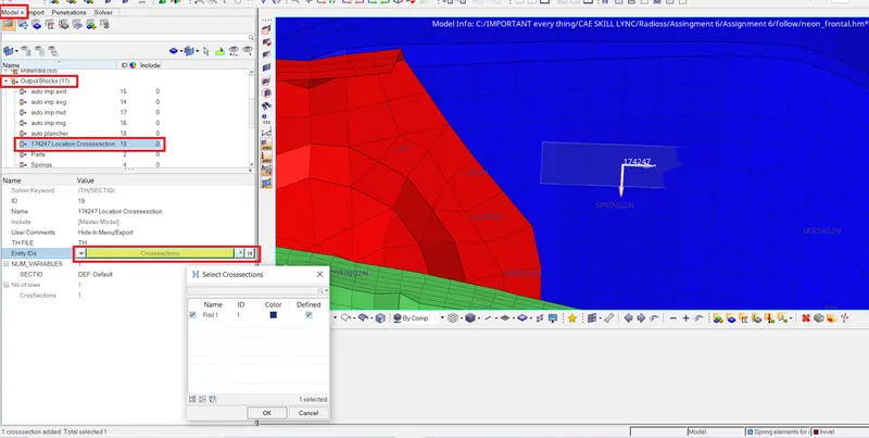
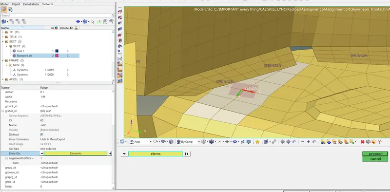
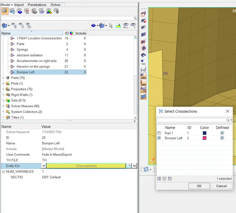
Request 2: Axial force received on the rails from bumper.
STEP 1: Creating new MOV collector in FRAME card
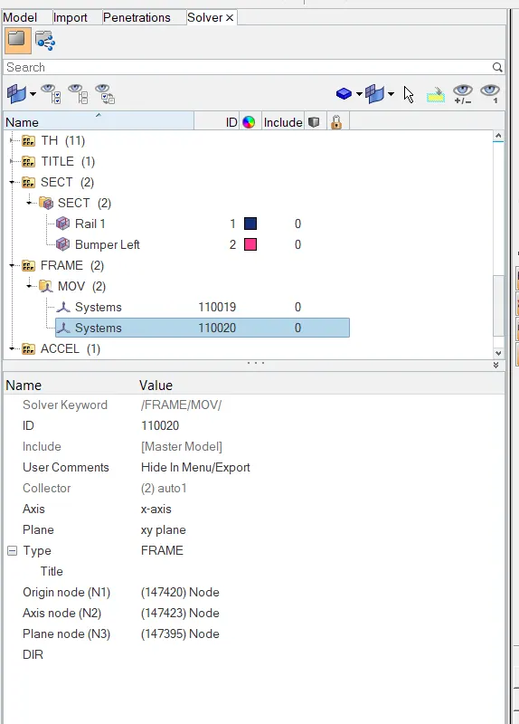
STEP 2: Creating SECT and giving parameters
STEP 3: Giving Output Request to Model Browser.
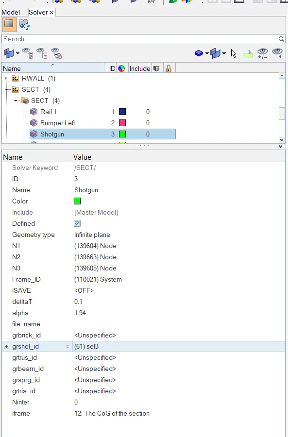
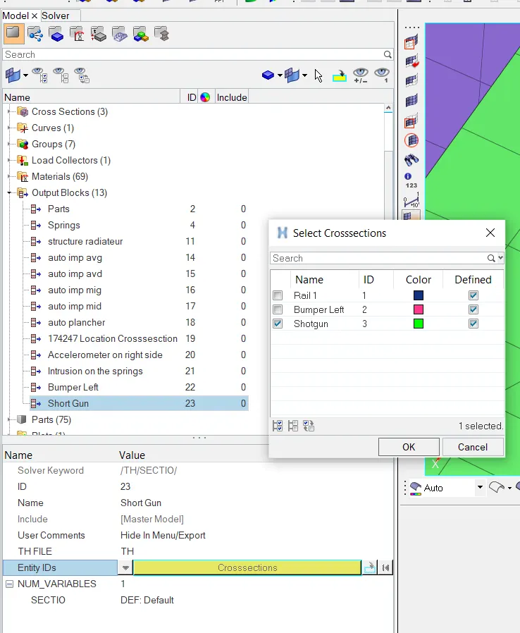
Request 3: Shotgun cross sectional forces.
STEP 1: Creating new MOV collector in FRAME card
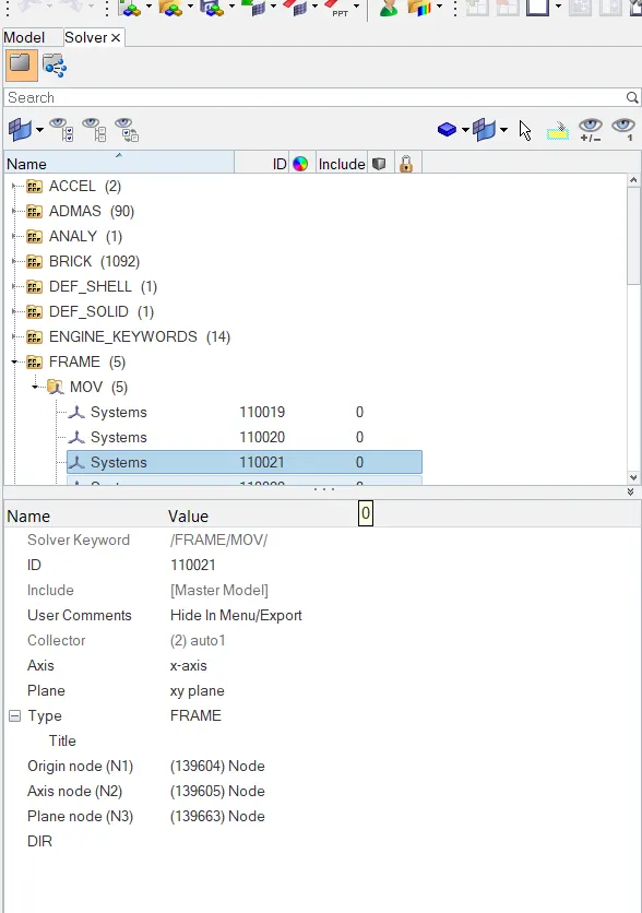
STEP 2: Creating SECT and giving parameters
STEP 3: Giving Output Request to Model Browser.
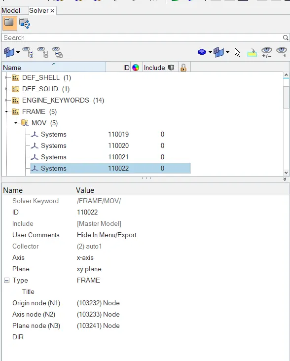
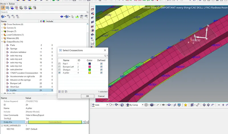
Request 4: A pillar cross section.
STEP 1: Creating new MOV collector in FRAME card
STEP 2: Creating SECT and giving parameters
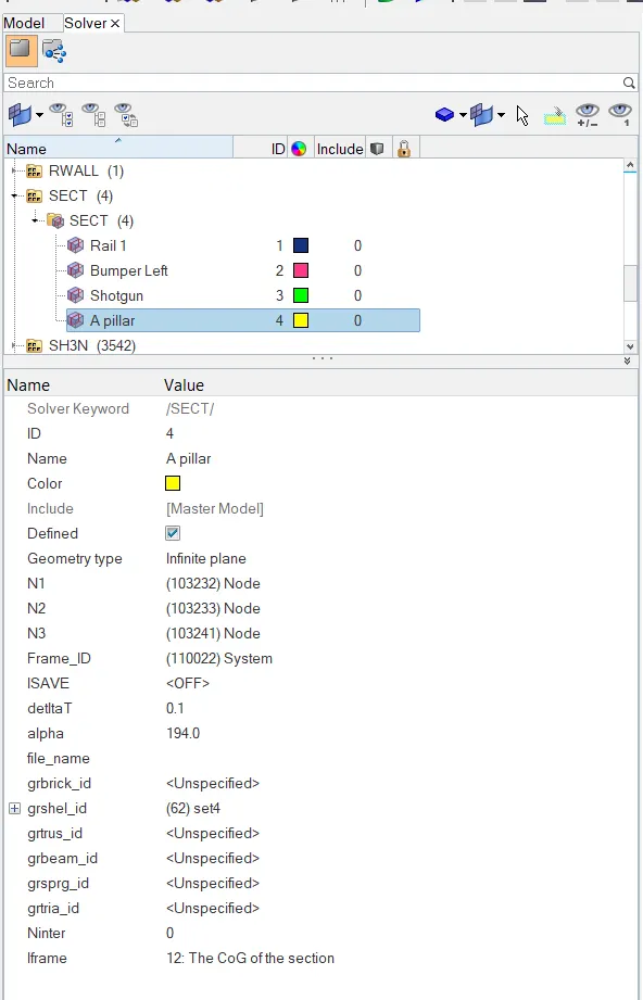
STEP 3: Giving Output Request to Model Browser.
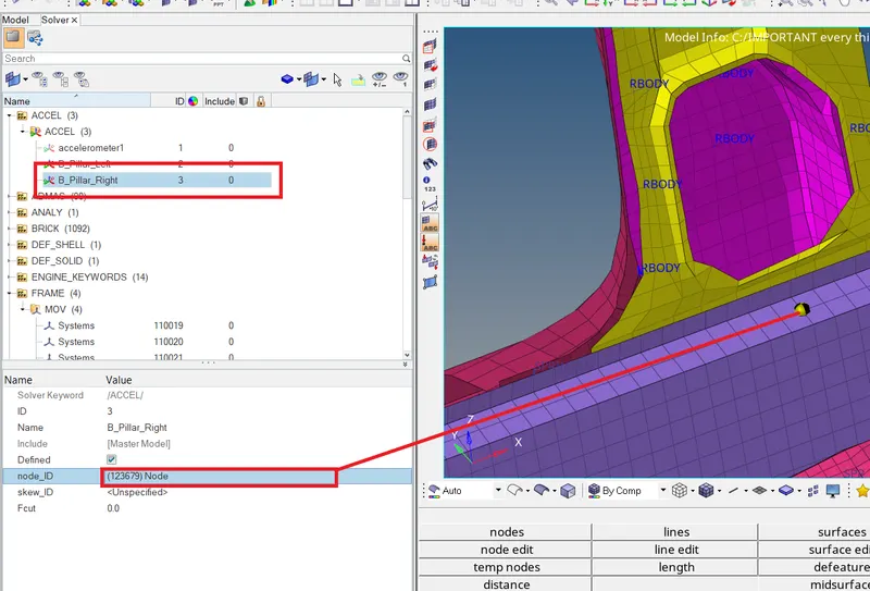
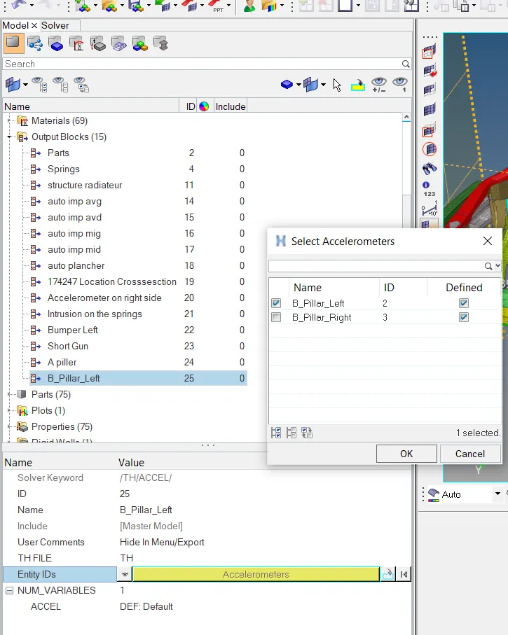
Request 5: Acceleration curve received on the accelerometer at base of B pillar
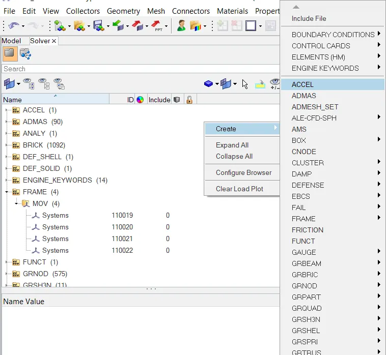
STEP 1: Creating Accelerometer ACCEL
Solver >> Create >> ACCEL
STEP 2: Assigning the node and parameters required.
STEP 3: Output Request for Model Browser
Request 6: Intrusions on the dash wall 66695,66244.
>> For node 66695
STEP 1: Creating one spring component
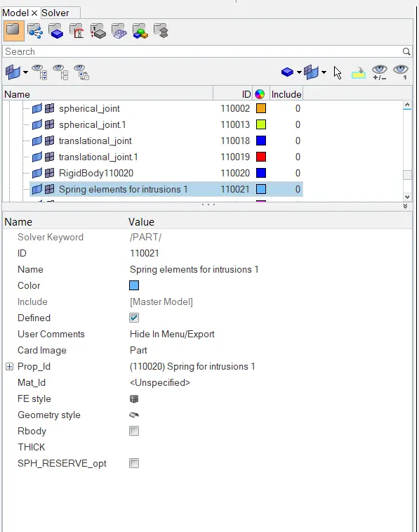
STEP 2: Creating a Property of the spring component.
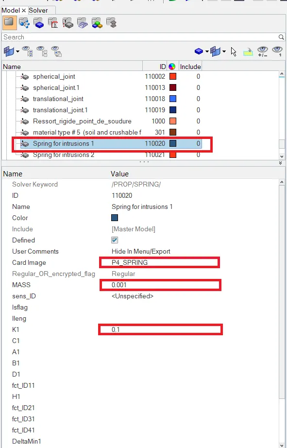
STEP 3: Output Request for Model Browser
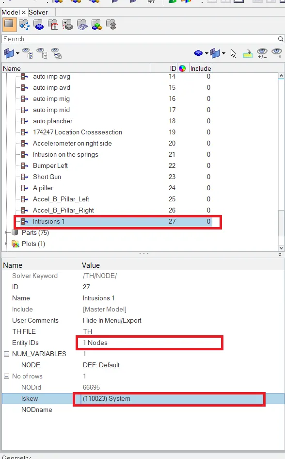
Similarly for the node 66244.
SIMULATION OH THE FRONTAL CRASH:
Step 1: Open Hypermesh Radioss Solver
Step 2: Analysis >> Radioss >> Enter required file location and set up and click Radioss for the simulation to precess.
Step 3: Open new tab to Hyper view.
Step 4: Select the .h3d file created by the simulation for results.
RESULTS:
Hypergraph 2D >> select _T01 type file to plot graphs.
Sectional Force through rail at node 174247:
Bumper:
Shotgun:
A Pillar:
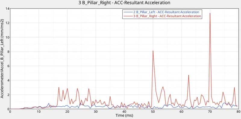
Accelerometer at base of B pillar:
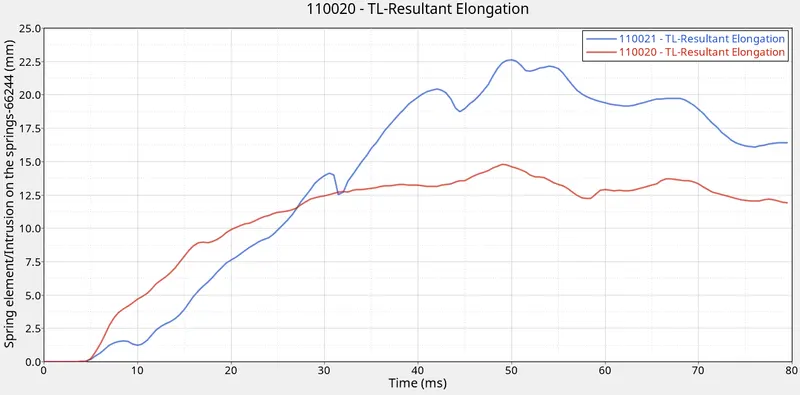
Intrusions:
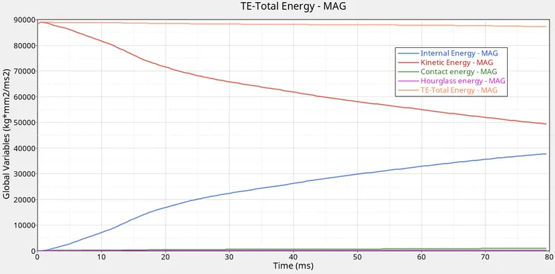
Energy Graphs:
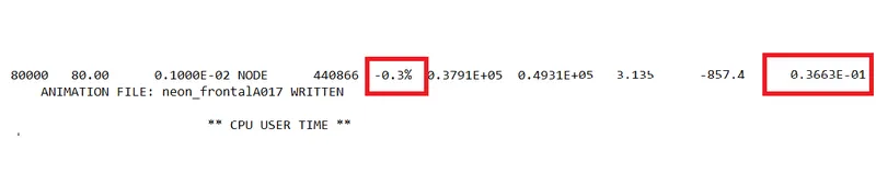
Number of cycles: 80001
Energy Error: 0.3%
Mass Error: 3.663%
We saw in the animation that the most deformation took place in the frontal area and the stress is then passed to the rest of the components of the car. We observed that the impact of the crash is taking mostly at the frontal region of the car and by looking at this we can say that the setting area of the driver and passenger will be also impacted which can cause injury to the passengers.
The energy graph is shown of Internal energy, Kinetic energy. Contact energy, Hourglass energy and Total energy Vs Time. We can see that Internal energy increases with respect to time whereas Internal energy starts falling down from its peak as time increases.
Contact energy hourglass energy graphs have values near to zero and Total energy remains almost constant as time increases
In accelerometer 1 and accelerometer 2, the curve fluctuates drastically during the crash. In Intrusion 1 and Intrusion 2 graph, the displacement curve linearly increases with respect to time.