Week 4- Challenge
Create 1D elements on the following component with given cross-section and DOF
- Rod element:- with only translational DOF and RBE2 link
Cross-Section: BOX- Dimension a= 12 mm
Dimension b=10 mm
Thickness t= 0.75 mm
- Beam element:- with all DOF and RBE3 link
Cross-Section: I Section- Dimension a= 8 mm
Dimension b= 10 mm
Dimension c= 8.5 mm
Thickness t1= 0.75 mm
Thickness t2= .6 mm
Thickness t3= .6 mm
- Bar element:- with only x and y DOFs With RBE3 link
Cross-section: CROSS section- Dimension DIM1= 5 mm
Thickness DIM2= 1.2 mm
Dimension DIM3= 10 mm
Thickness DIM4= 1.2mm
- & e. apply the mass of magnitude 10 with RBE2 link
- Join the two components with Spring elements
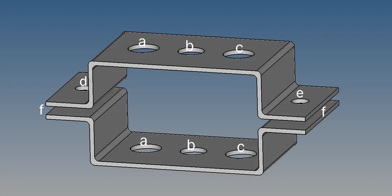
Solution::
Importing of the model:
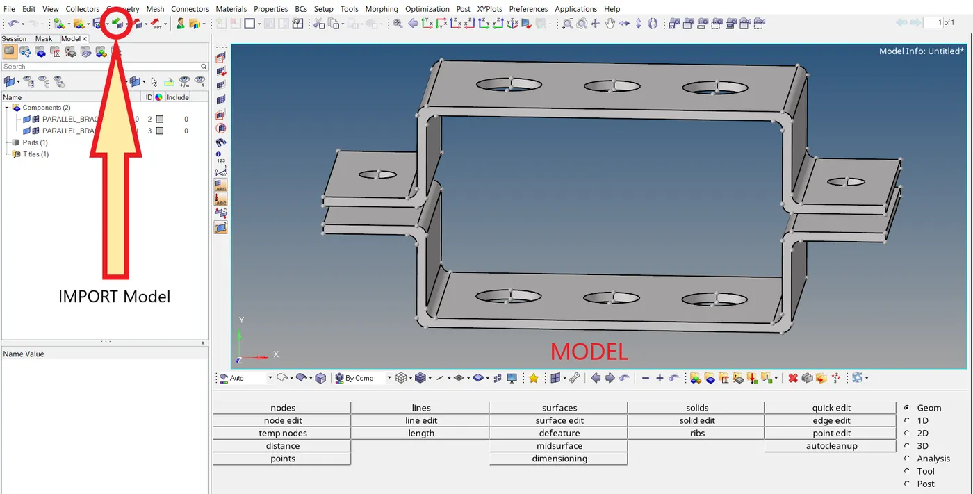
- Any type of models which are in the compatible with Hypermesh can be imported from the circled icon in the above image.
Extraction of Midsurfaces: Geom -- > midsurface
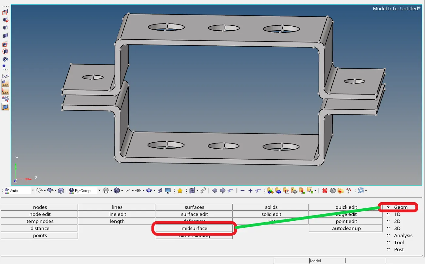
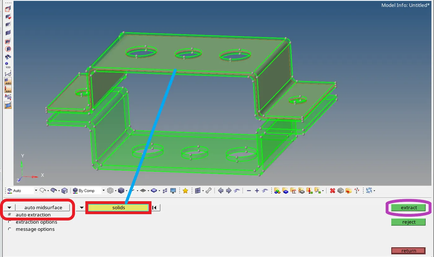
- Auto midsurface is the most commonly used for the creation of midsurfaces, if needed midsurface creation can be tweak in the extraction options and auto midsurface settings.
- Click on the solids and select the solid model for which the midsurface is to be created and click extract for the creation of the required midsurface.
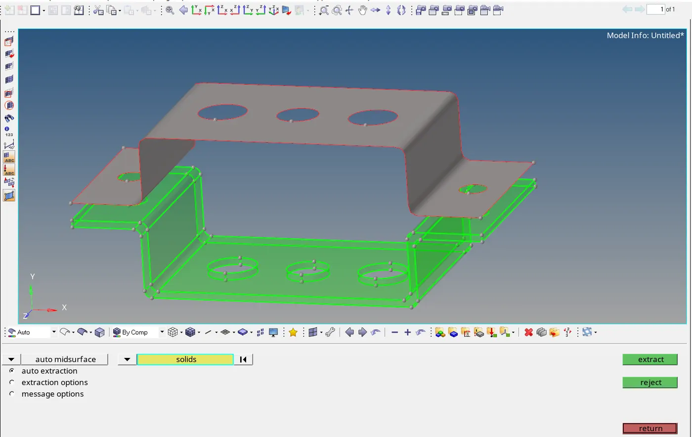
- Required midsurface for the first bracket is created.
- Similarly, all the rest of the midsufaces can be created.
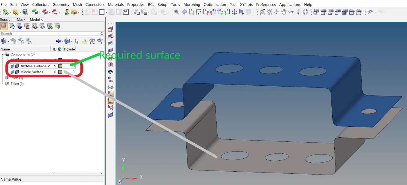
- When our required surface and created surface are different as shown in the above image, the surfaces can be organized.
Organizing the surface: Tool -- > organize
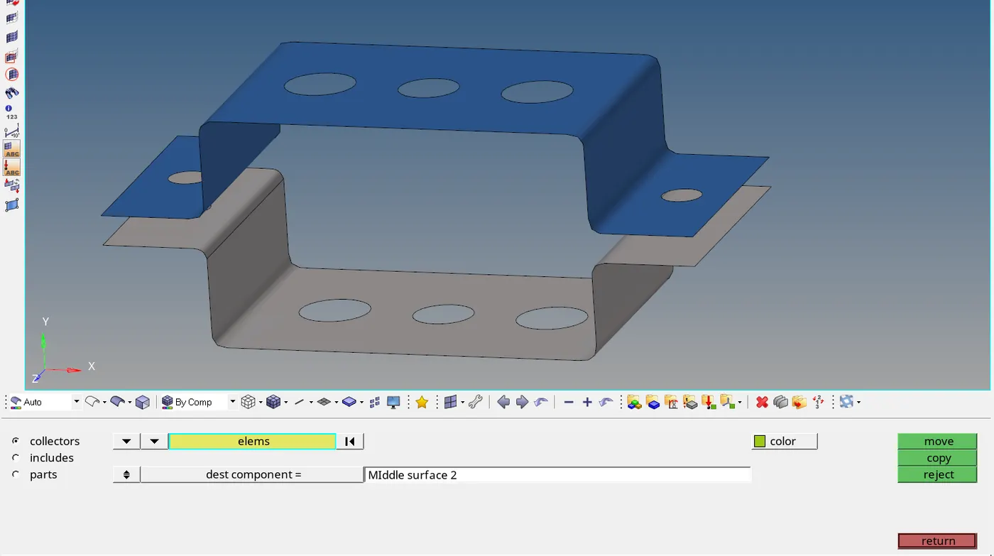
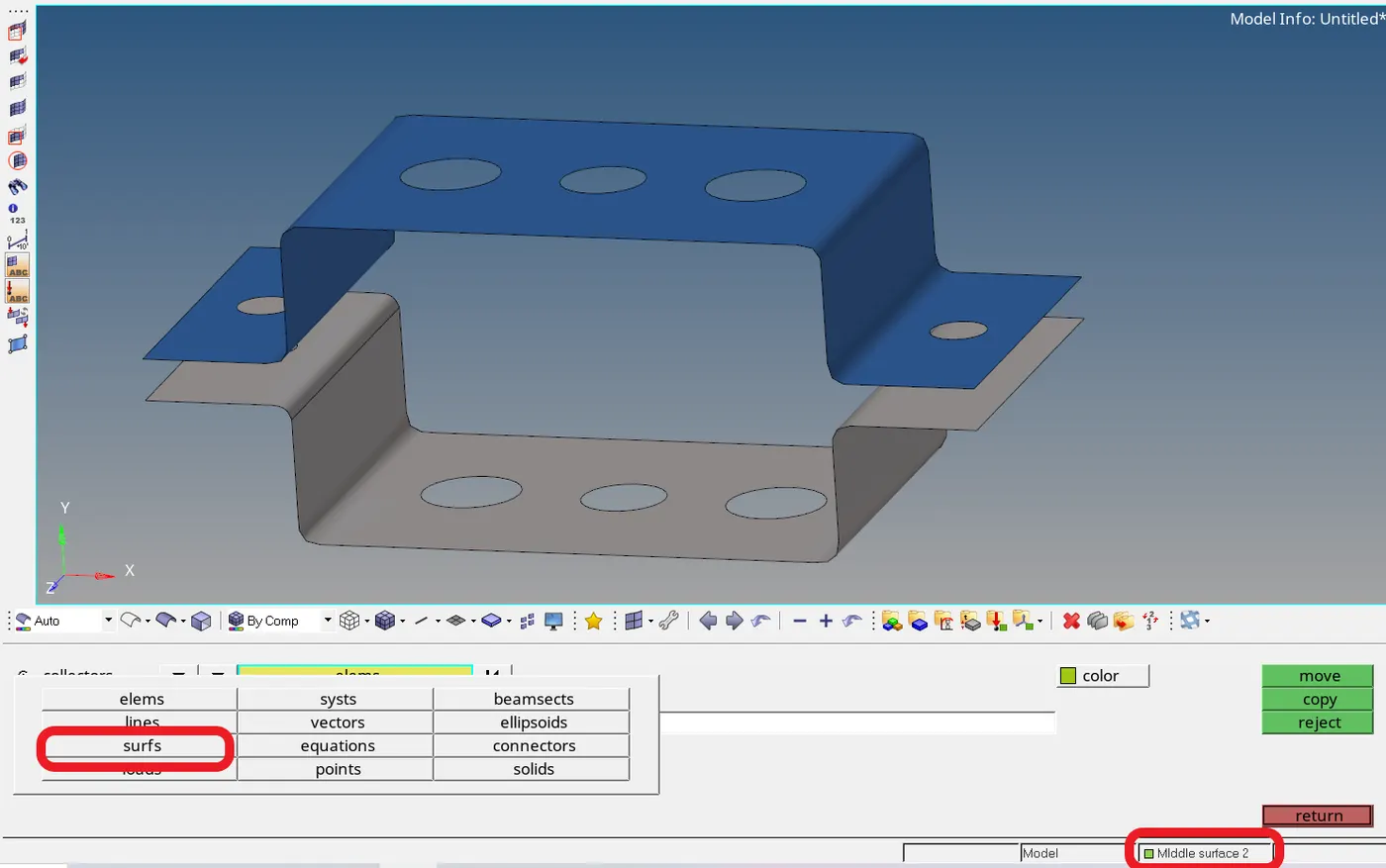
- First, we need to verify that the required surface is preselected or not by looking at the right bottom of the window which is boxed in red in the above image.
- After verifying, click on the surfs to select the other surface and click move to organize.
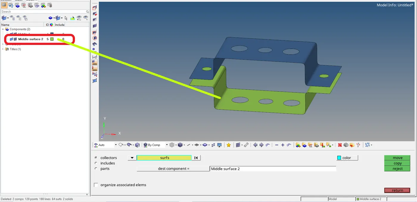
- The surface is organized as required.
Creation of washer splits (For good mesh): Geom -- > quick edit -- > washer split
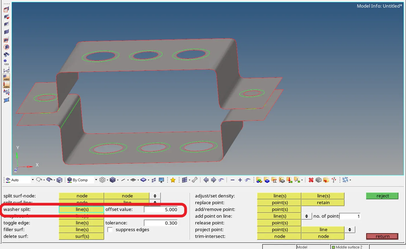
- Enter the offset value of the washer split and select the required circles by line(s).
Creation of the mesh: 2D -- > mesh
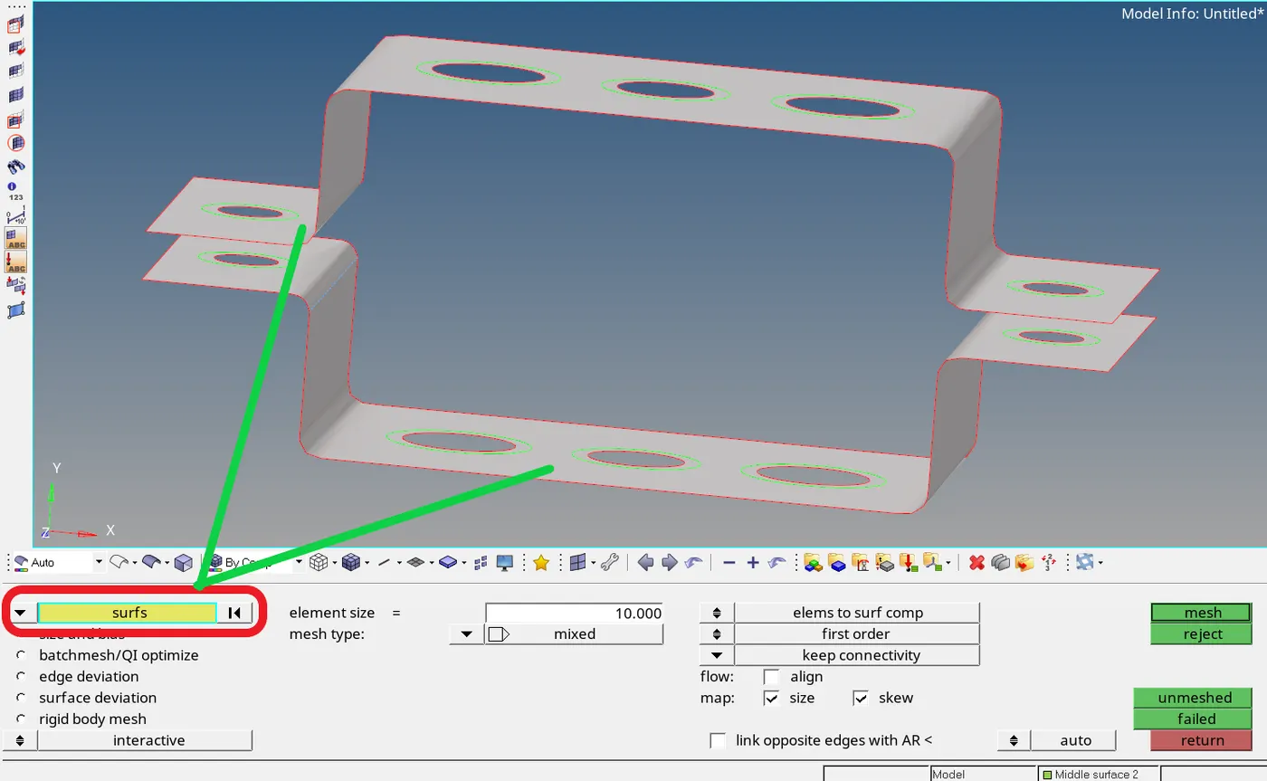
- Click on the surfs and select the surfaces to mesh and after entering the element size, mesh type click mesh on the right for the creation of the mesh.
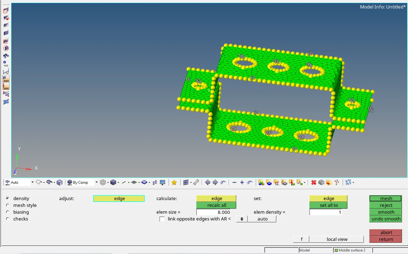
- Toggle the no. of nodes and other adjustments as required and click on mesh for the final mesh creation.
Creation of RBE2 and RBE3 links: 1D -- > rigids (for RBE2) and rbe3 (for RBE3)
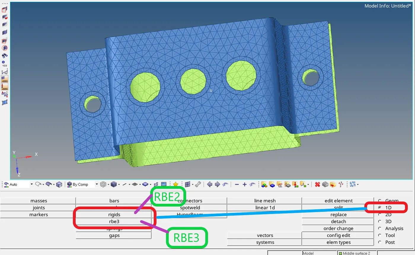
Creation of RBE2 element:
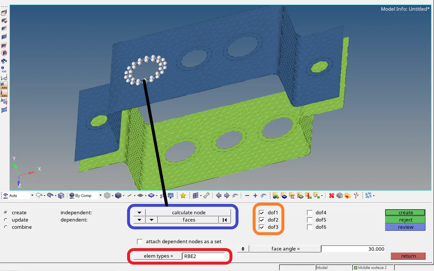
1D -- > rigids
- Elem types in the lower red coloured box RBE2 must be selected and nodes for the creating elements are selected from the blue coloured box in the above image and the selection of degrees of freedom are selected from the ticked boxes on the right as required for the element.(dof 1,2,3 are X,Y,Z translation and dof 4,5,6 are X,Y,Z rotations respectively )
- Similarly for RBE3 elements creation in 1D -- > rbe3
Creation of ROD : 1D -- > rods
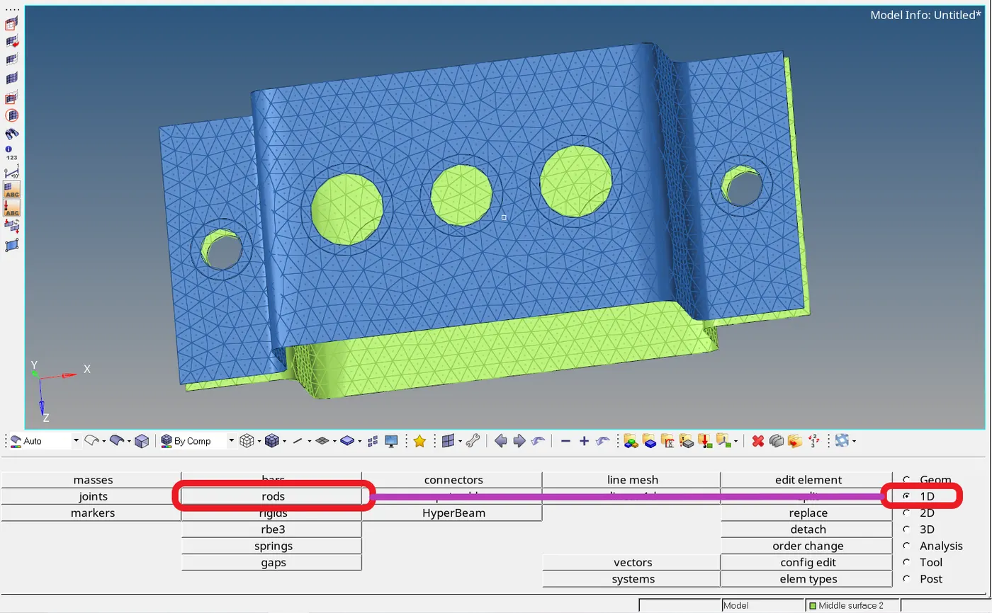
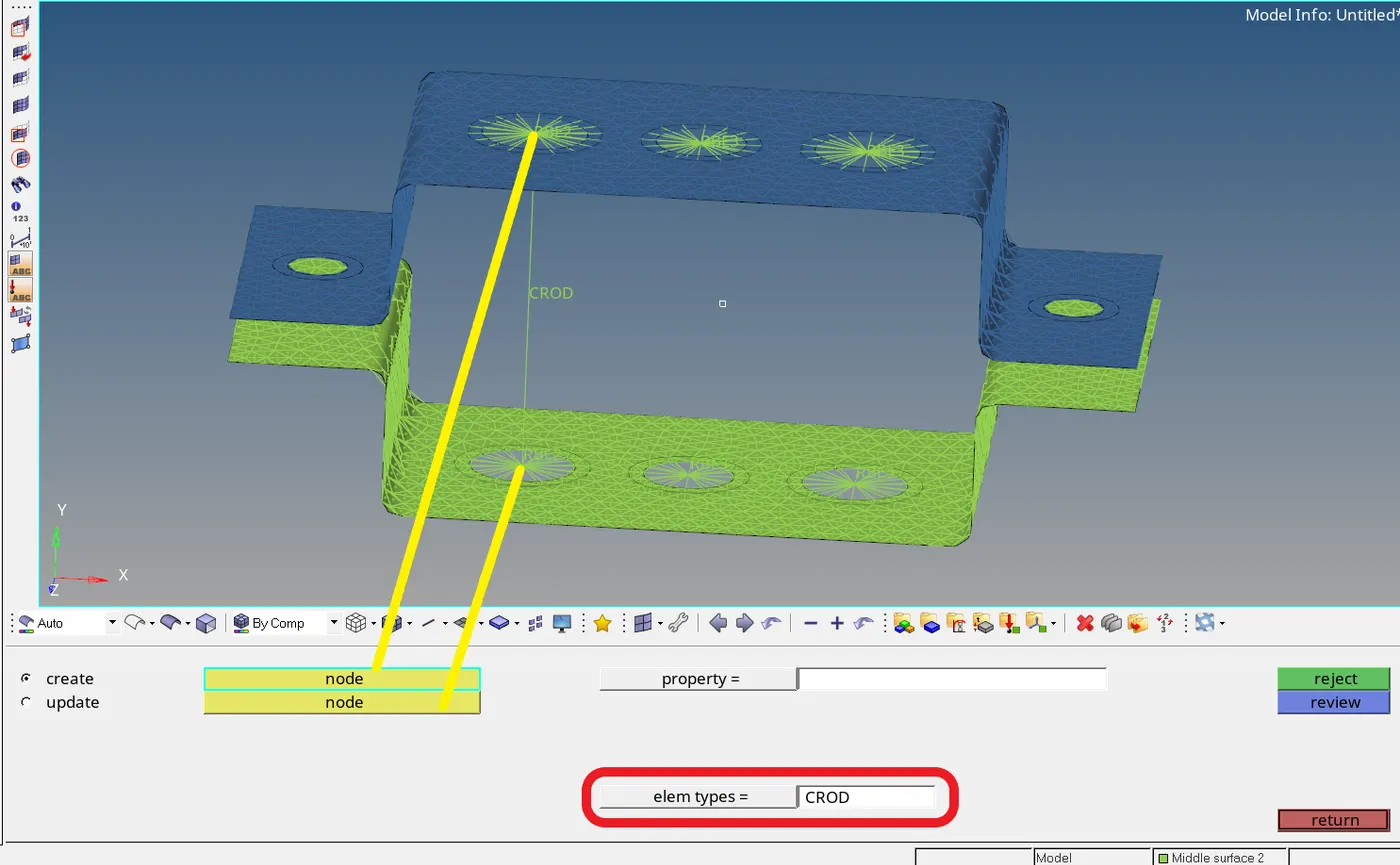
- First set the elem types to CROD and select the two nodes for the creations of the CROD element.
Creation of BEAM element: 1D -- > bars
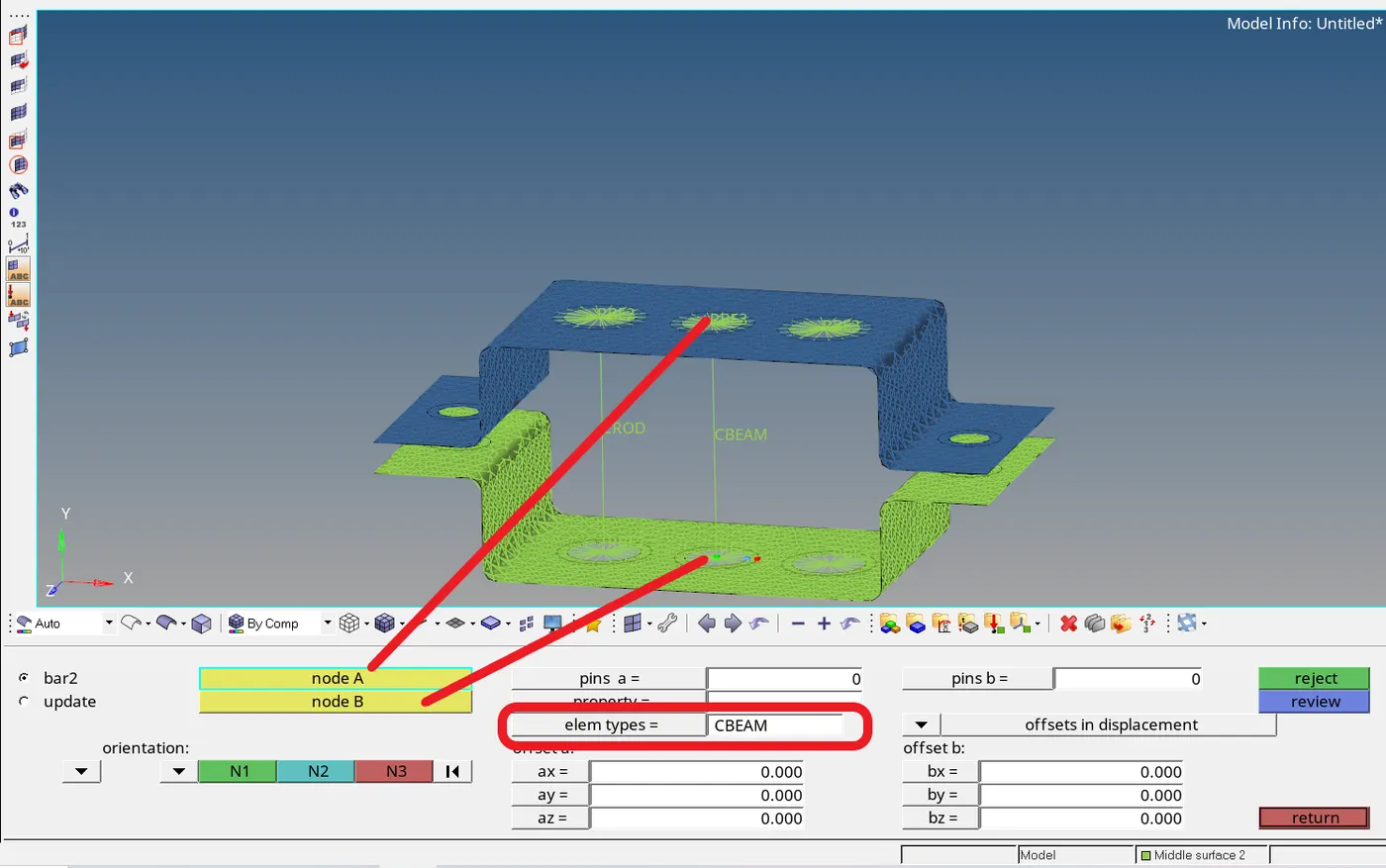
- Similarly to the creation of rod element go to 1D -- > bars and first need to set the elem types to CBEAM.
- Select the two nodes A, B and set the orientation as required and the BEAM element is created.
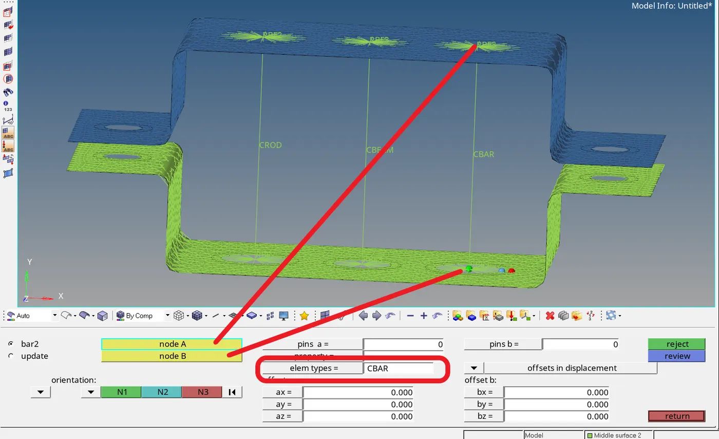
- Similar to BEAM creations of BAR element is done in 1D -- > bars.
Creation of three Hyperbeams: 1D -- > HyperBeam

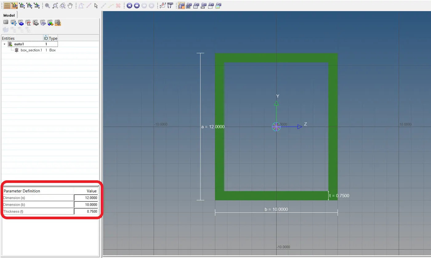
- The variable’s a,b and t can be changed from the Parameter Definition.
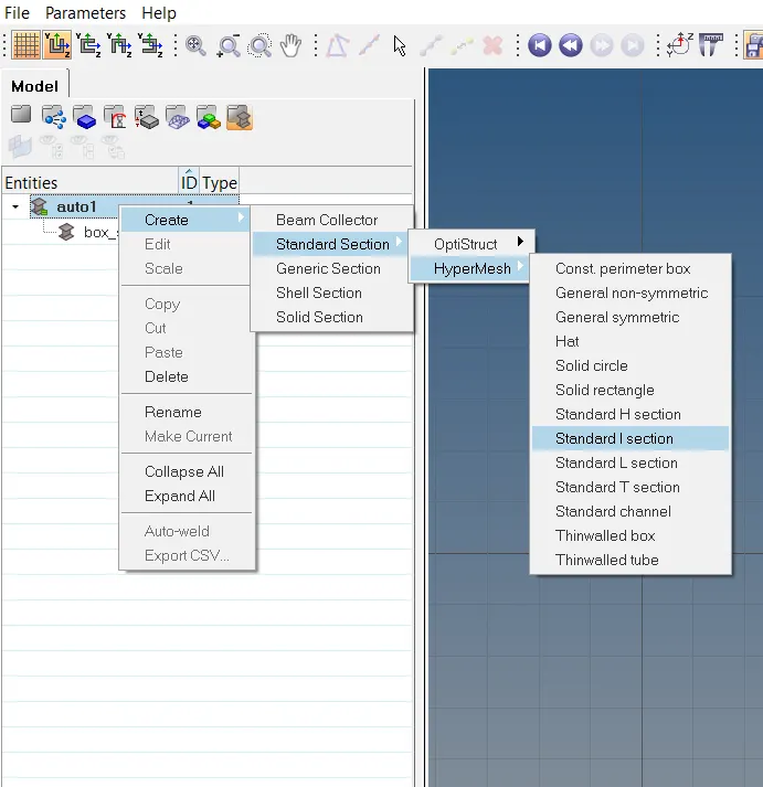
- Creation of new Hyperbeams can be done as shown in the image above.
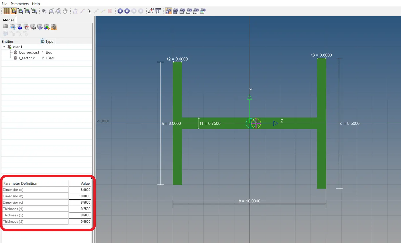
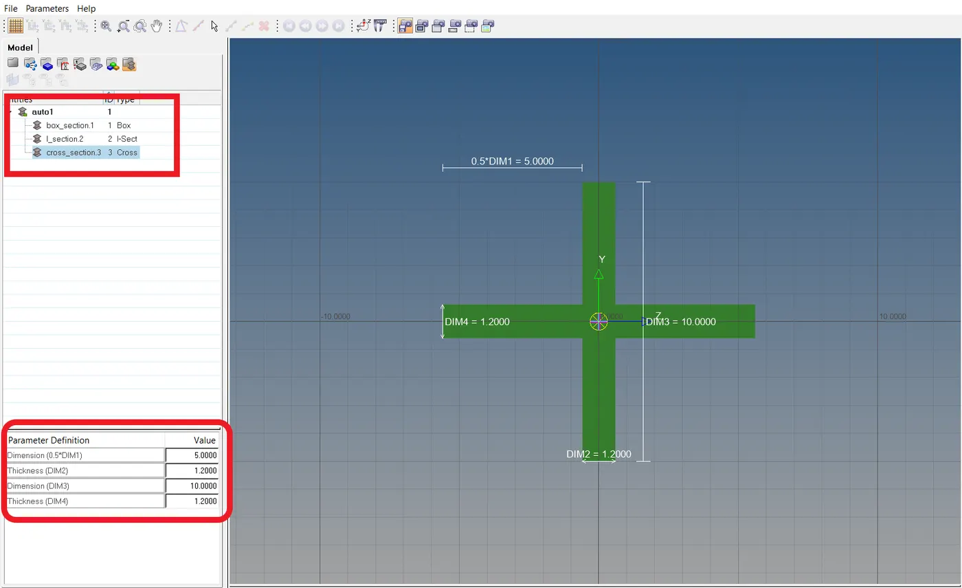
- Similar to the box section I and cross-sections are created.
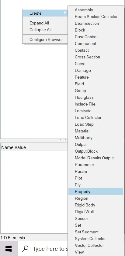
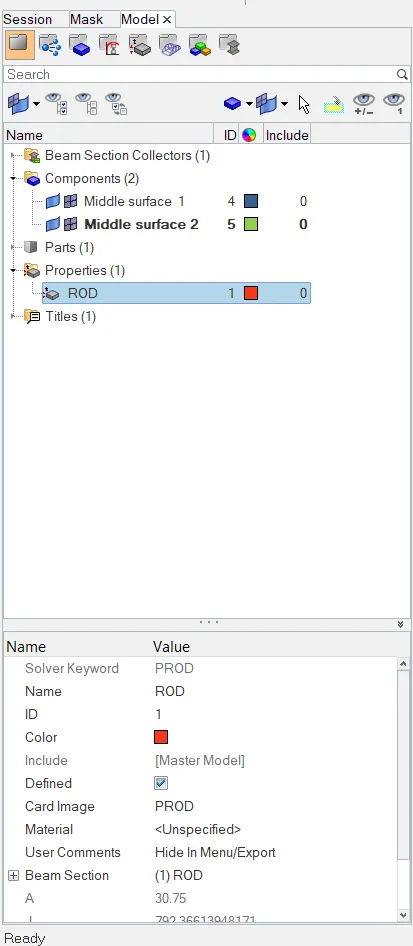
Creation of Properties:
 -->
-->  -->
-->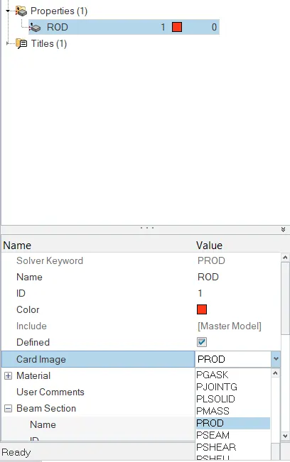
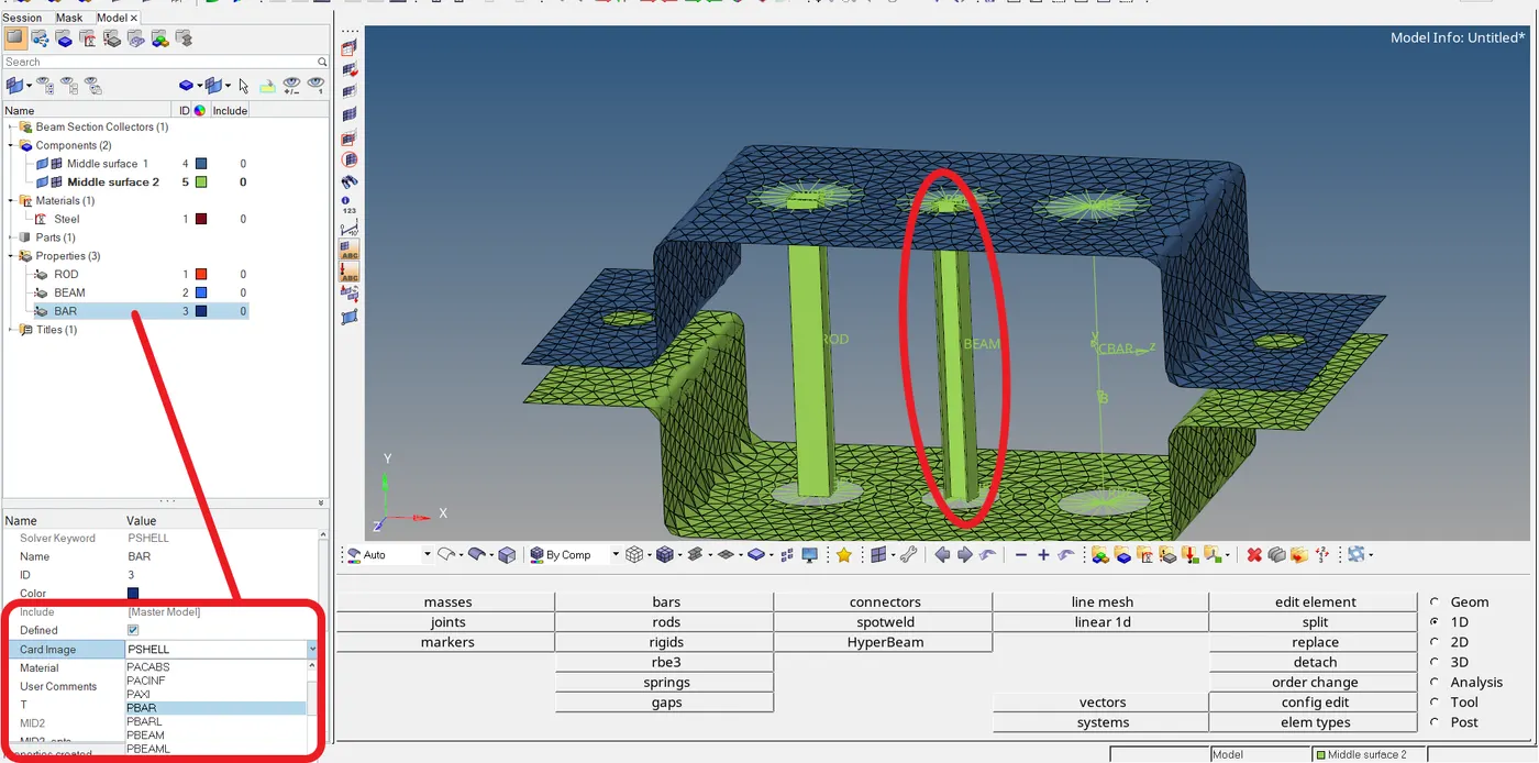
- In the Card Image right type of link should be selected for assigning the right property.
Updating the CROD: 1D -- > rods
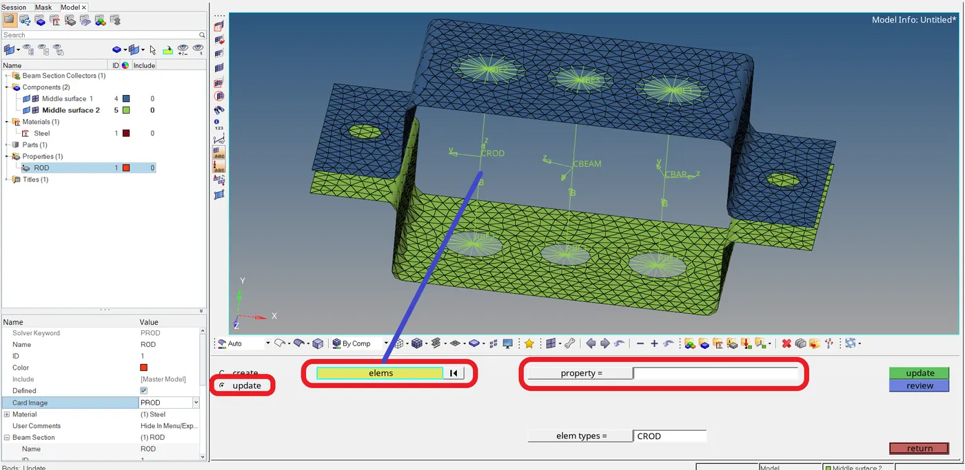
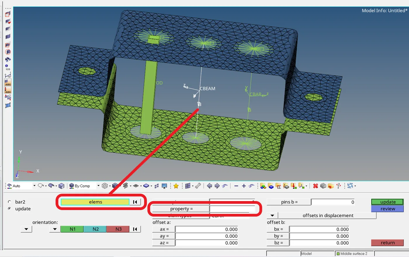
- First, after going to rods the panel must be changed to update from create.
- Then select the CROD link and click on the property to add the created ROD property.
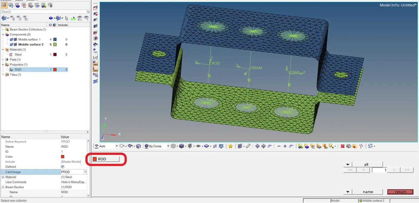
- Select the ROD to update the property.
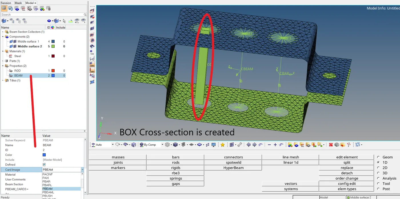
- It can be seen that the box cross-section is created.
- And similar to the ROD property BEAM and BAR can be created and assigned to their corresponding links.
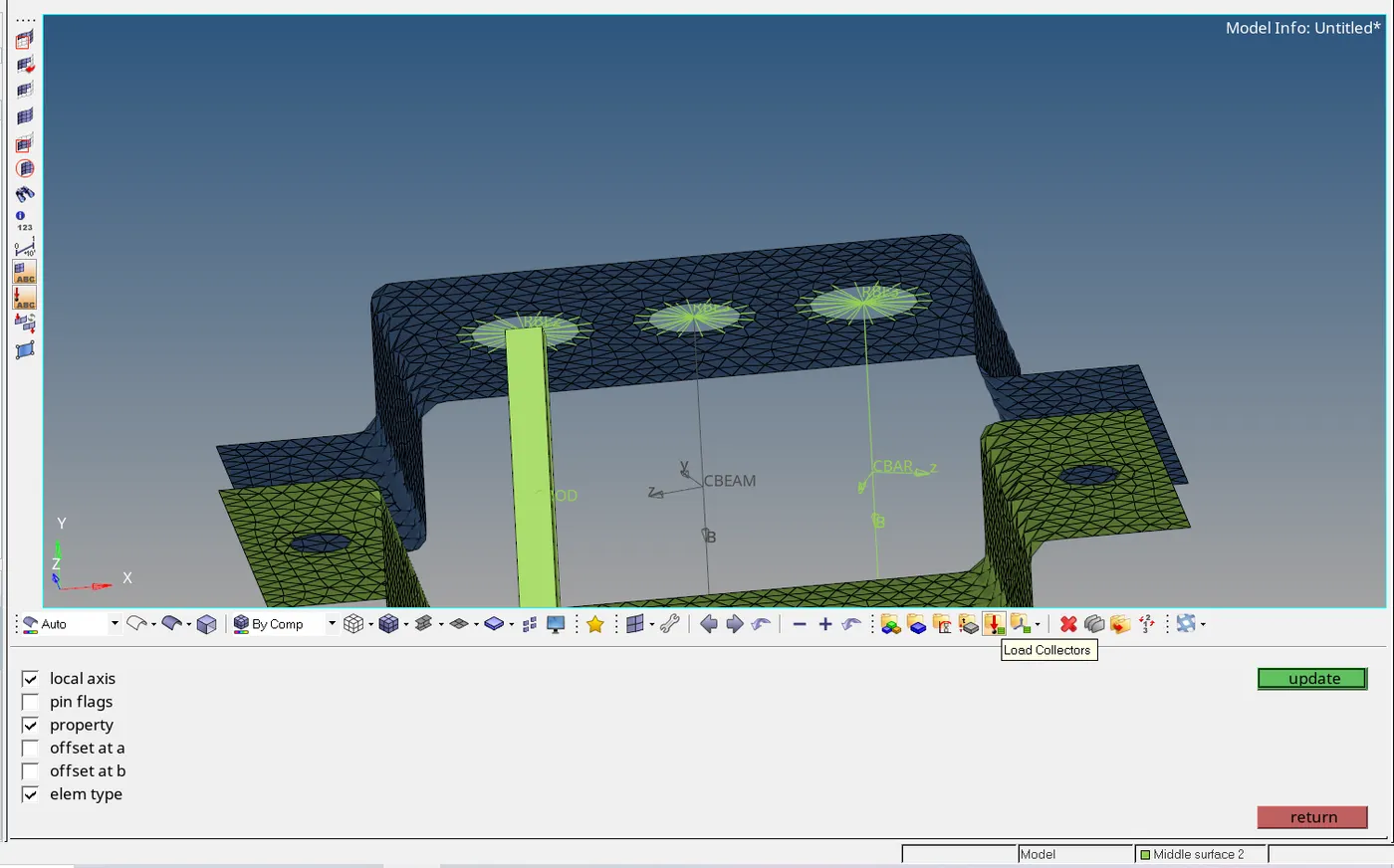
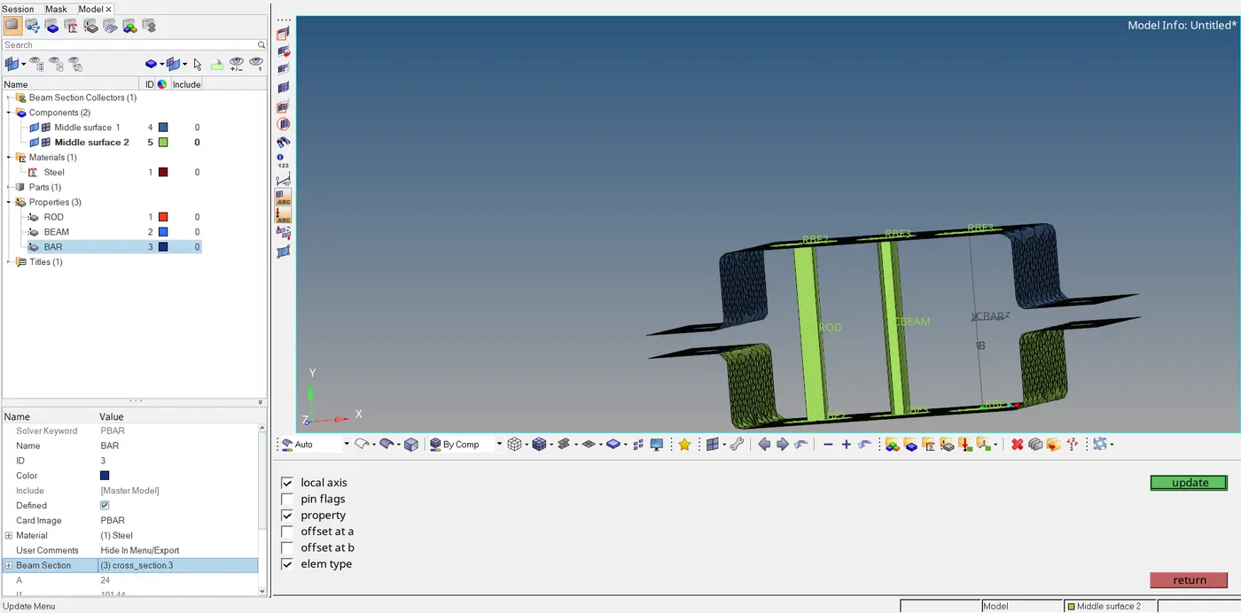
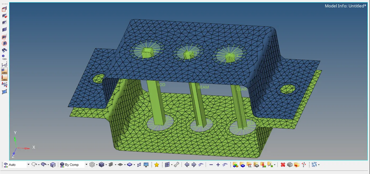
- All three cross-sections are created as required.
d. & e. apply the mass of magnitude 10 with RBE2 link:-
Mass element creation:
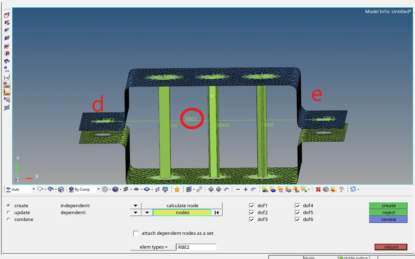
- First, created the RBE2 element link.

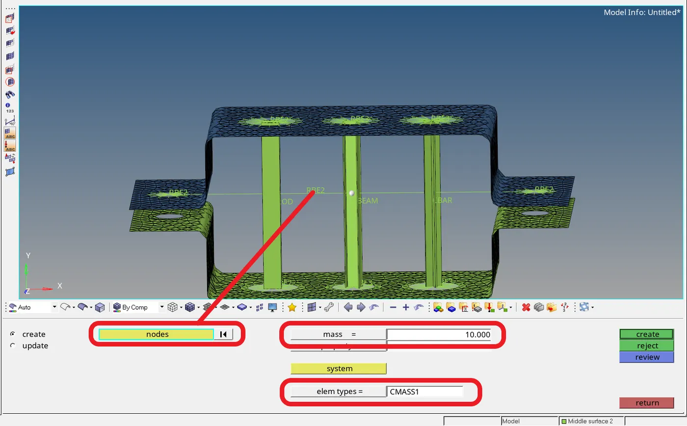
- First going to the masses panel the elem types should be set to CMASS1.
- Enter the mass to be 10 as required, select the link element and click create for the creations of the mass element.
f. Join the two components with Spring elements:
1D -- > springs

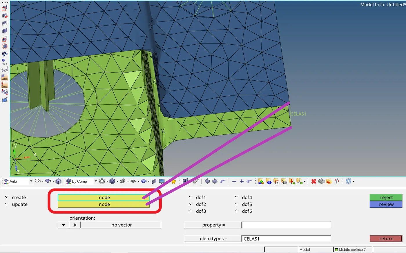
- Selection of the two required nodes creates the spring element across those nodes.
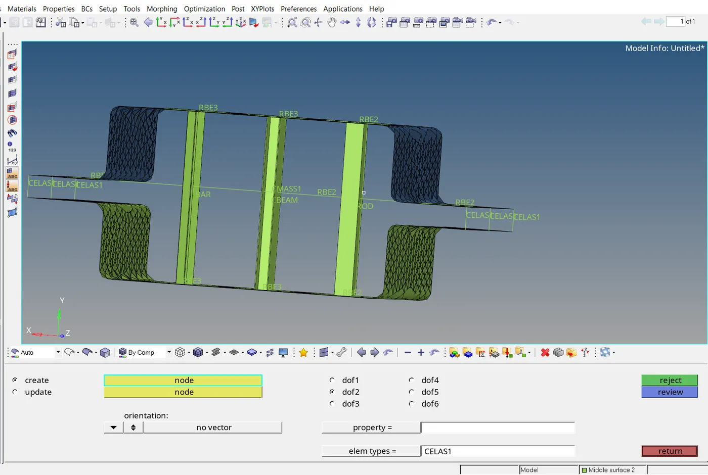
- Similarly, all the spring elements are created at all the required places.