Week 9-Challenge
OBJECTIVE: To create connectors and attach the various parts of the given model.
PROCEDURE:
- The given model is imported into HyperWorks and the required geometry cleanup is done.
- Next, 2D meshing of all the components is done with an element size of 5mm. (F12>surfs=displayed>elem size=5>mesh)
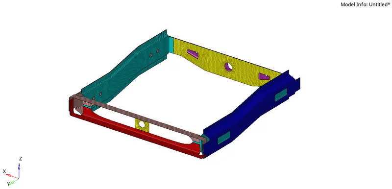
- The connectors are generated between the various components one by one, depending upon the type of connector required between them.
- Since the challenge is primarily on creating connectors, much attention is not given to mesh quality.
1. Right_Rail_2 & Front_truss_1:- Seam-Quad(angled+capped+L) connector
- Hide all the components except for Right_Rail_2 & Front_truss_1.
- Then go to 2D >connectors>seam>type= Seam-Quad(angled+capped+L)
- The spacing is set to 5 (which is the same as the target element size of 5mm)
- Tolerance is set to 5 taking into consideration the gap between the 2 components.
- Select the node list where the connector is to be created. Then select the 2 components under the ‘connect what’ option.
- Keeping the rest of the values and options as default the seam connector is created.
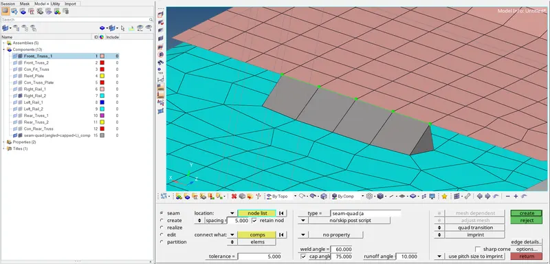
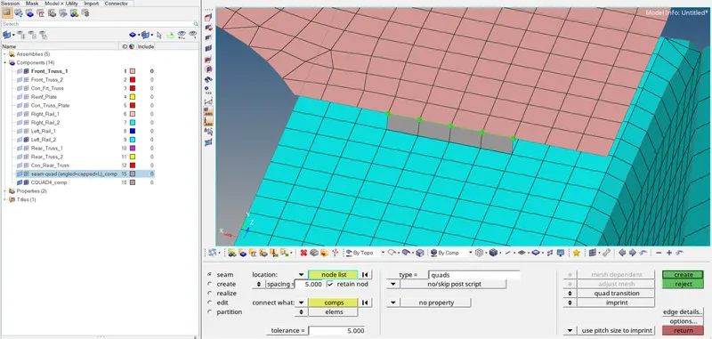
2. Left_Rail_2 & Front_truss_1:- Quad elements
- Hide all the components except for Left_Rail_2 & Front_truss_1.
- Then go to 2D >connectors>seam>type= quads
- Rest all the steps are repeated exactly as listed above for ‘Right_Rail_2 & Front_truss_1:- Seam-Quad(angled+capped+L) connector’.
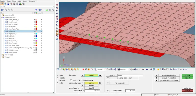
3. Front_truss_2, Front_truss_1 & Right_Rail_1:- Spot weld with 3 Layers and 5 mm Diameter
- Hide all the components except for Front_truss_2, Front_truss_1 & Right_Rail_1.
- Then go to 2D >connectors>spot>type= weld
- Tolerance is set to 10 taking into consideration the gap between the components.
- Select the nodes where the connector is to be created. Then select all 3 components under ‘connect what’.
- The ‘num layers’ value is set to ‘total 3’ and the diameter value is set to 5.
- Keeping the rest of the values and options as default the spot weld is created.
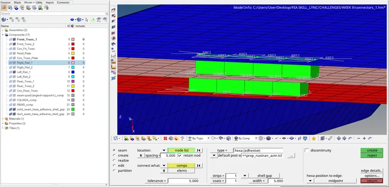
4. Front_truss_2, Front_truss_1 & Left_Rail_1:-Hexa (Adhesive)
- Hide all the components except for Front_truss_2, Front_truss_1 & Left_Rail_1.
- Then go to 2D >connectors>seam>type= hexa(adhesive)
- The spacing and tolerance is set to 5. The ‘width’ is also set to 5.
- Select the node list where the connector is to be created. Then select the first 2 components under the ‘connect what’ option.
- Keeping the rest of the values and options as default the connector is created.
- After connecting the first 2 components, connect the next 2 components.
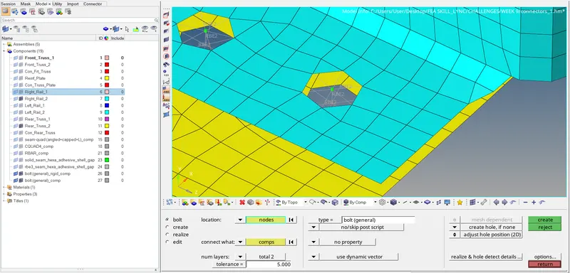
5. Rear_truss_2 & Right_Rail_2:- Bolt Connector
- Hide all the components except for Rear_truss_2 & Right_Rail_2.
- Then go to 2D >connectors>bolt>type= bolt(general)
- Tolerance is set to 5 taking into consideration the gap between the 2 components.
- The ‘num layers’ value is set to ‘total 2’.
- Select the nodes where the bolt connector is to be created. Then select the 2 components under the ‘connect what’ option.
- Since there are no holes present at the location where the bolt connector is to be created, we need to select the option, ‘create hole, if none’, so that the connector can be realized.
- Keeping the rest of the values and options as default the connector is created.
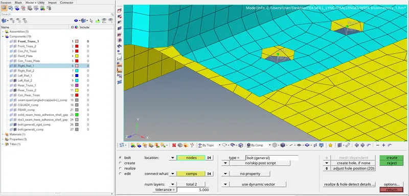
6. Rear_truss_2 & Left_Rail_2:- Bolt Connector
- Hide all the components except for Rear_truss_2 & Left_Rail_2.
- Then all the steps listed above for ‘Rear_truss_2 & Right_Rail_2:-Bolt Connector’ are repeated.
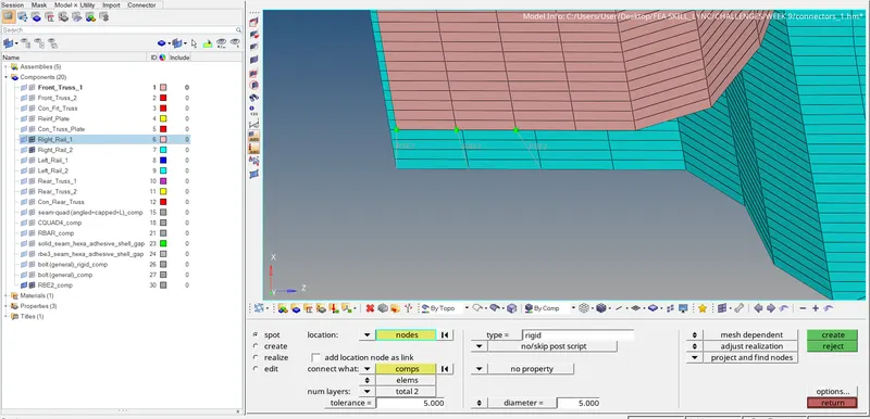
7. Right_Rail_1 & Right_Rail_2:- Spot-weld with Rigid Elements
- Hide all the components except for Right_Rail_1 & Right_Rail_2.
- Then go to 2D >connectors>spot>type=
- Tolerance is set to 5 taking into consideration the gap between the components.
- Select the nodes where the connector is to be created. Then select the 2 components under ‘connect what’.
- The ‘num layers’ value is set to ‘total 2’ and the diameter value is set to 5.
- Keeping the rest of the values and options as default the spot weld is created.
8. Left_Rail_1 & Left_Rail_2:- Spot-weld with Spring Elements
- Hide all the components except for Left_Rail_1 & Left_Rail_2.
- Except for changing the type to ‘spring’, rest all the steps are repeated exactly as listed above for ‘Right_Rail_1 & Right_Rail_2:- Spot-weld with Rigid Elements’.
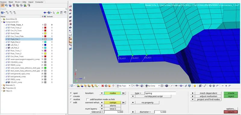
9. Rest all the component left are joined with the suitable connectors:
- Reinf_Plate and Front_Truss_2 with seam weld,
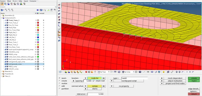
- Reinf_Plate and Front_Truss_2 with seam weld,
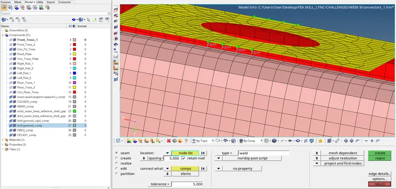
- Rear_Truss_1 and Rear_Truss_2 with spot weld,
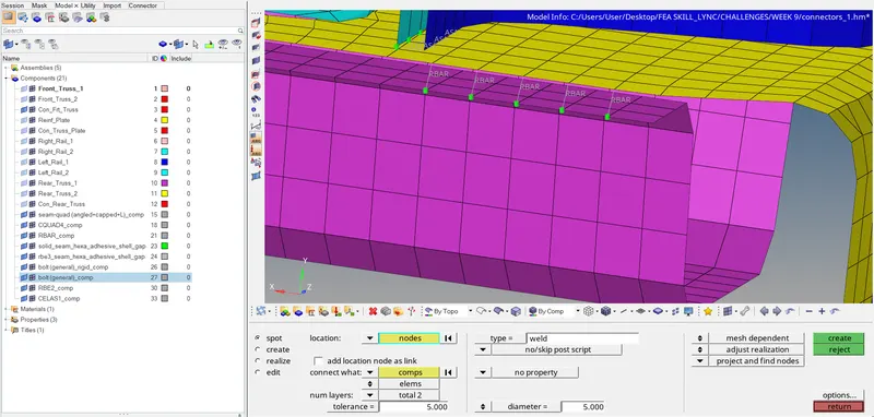
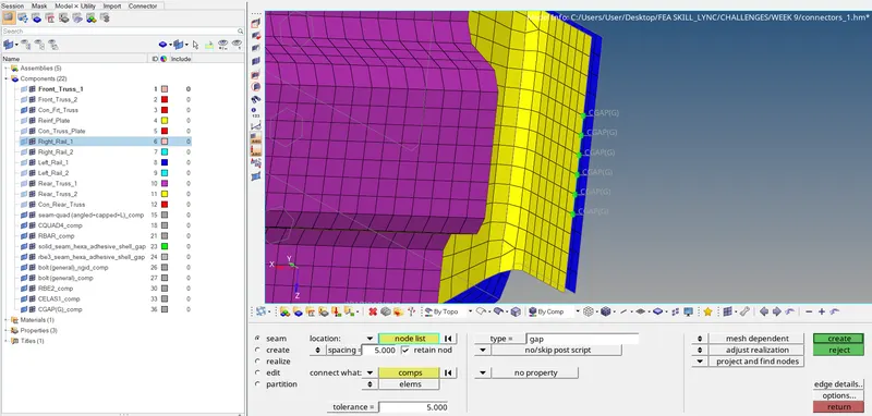
- Right_Rail_1 and Rear_Truss_2 with seam gap,
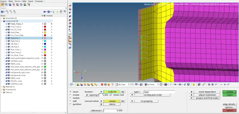
- Left_Rail_1 and Rear_Truss_2 with seam gap,
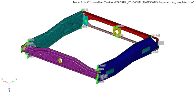
FINAL MODEL IMAGE:
CONCLUSION:
Connectors were deployed on the given components as per the given connection details. Hence, was able to gain a clear understanding of how various connections like seam, spot weld, adhesives, etc. that are employed between components are implemented in a meshed model.