Week 12:Project 2-Meshing of Rear Wheel Holder challenge
OBJECTIVE:
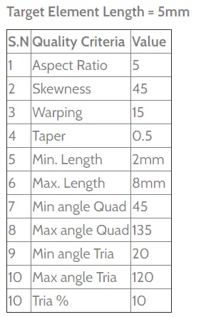
To mesh the given Floor Panel by following the given Quality Criteria and to assign the corresponding thickness to the elements.
INTRODUCTION:
The floor pan is a large sheet metal stamping that is welded onto the floor or underside of your car. The model provided here is a part of the floor pan that is usually present inside the trunk of the car and it is designed so as to accommodate the spare wheel of the car.
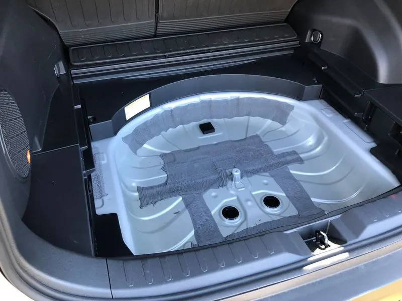
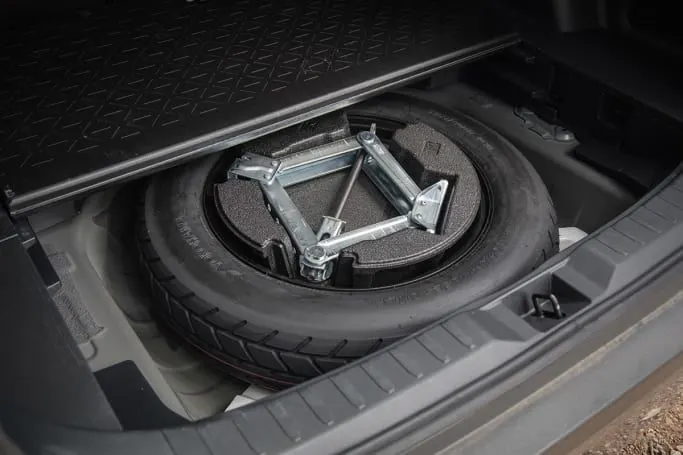
Fig 1: Floor Pan
CAD MODEL IMAGE:
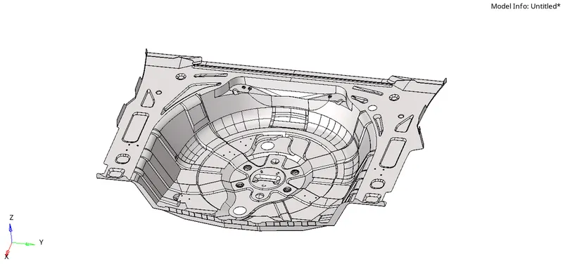
Fig 2: CAD Model
PROCEDURE:
1) Import the model into Hypermesh.
The given floor panel model is imported into Hypermesh using the import option on the menu bar.
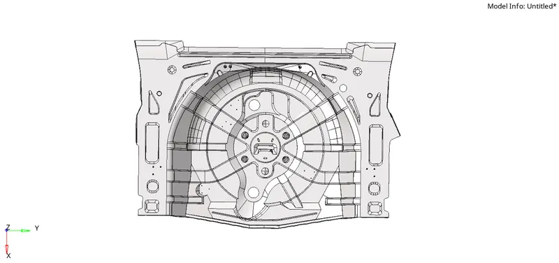
Fig 3: Imported Model
Since there are multiple components present within the model, all the components are organized into a single component using the 'organize' tool.

Fig 4: Organize Tool
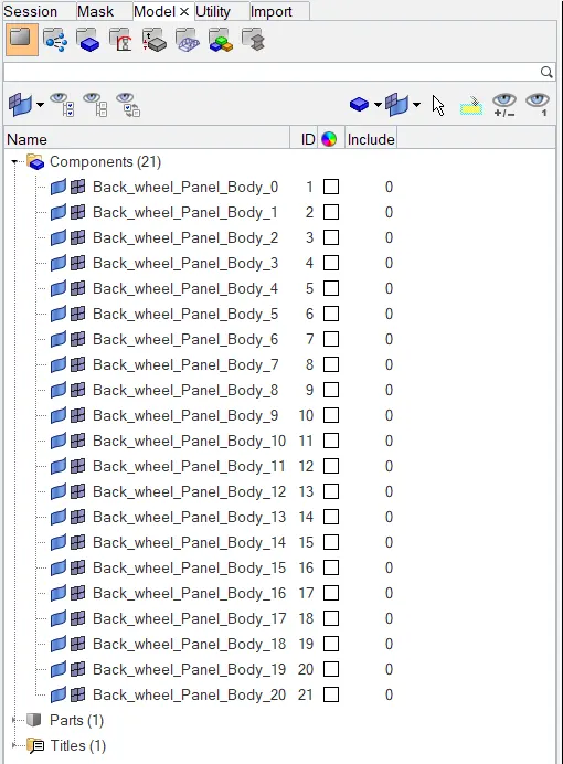
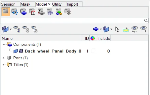
Fig 5: Multiple Components organized into a single Component
2) Geometry Cleanup
Before extracting the mid surface from the model, ensure that the model surface is perfect and free from errors like free edges, duplicate surfaces and missing surfaces. If any defects are found then the required geometry cleanup needs to be done using the various tools such as toggle edge, filler surf, replace points etc. available under the quick edit panel. (F11 (or) Geom>quick edit)

Fig 6: Quick Edit Panel
By viewing the model in the wireframe mode, the various defects in the surface geometry such as free edges (indicated by red lines) and duplicate surfaces (shared edges indicated by yellow lines) can be easily found out and rectified.
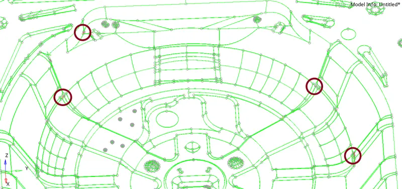
Fig 7: Wireframe mode to view the defects
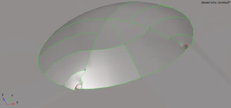
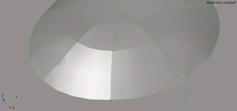
Fig 8: Using Replace Points
On the model, if any lines are too close to each other or if the distance between the lines is less than the minimum element length, then one of the lines needs to be suppressed using the toggle edge option. Otherwise, on meshing, elements that fail the minimum element length criteria will be created between the closely spaced lines. Also, toggle edge can be used to close small gaps between surface edges.
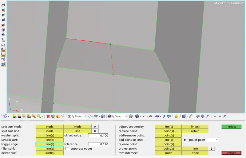
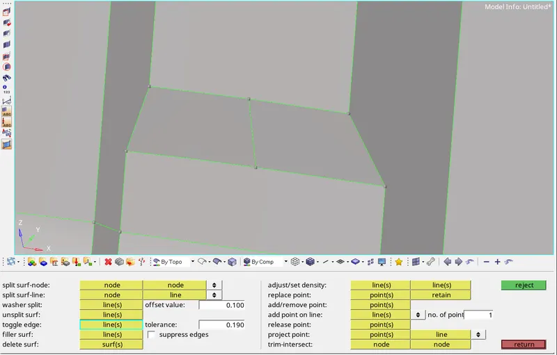
Fig 9: Toggle Edges
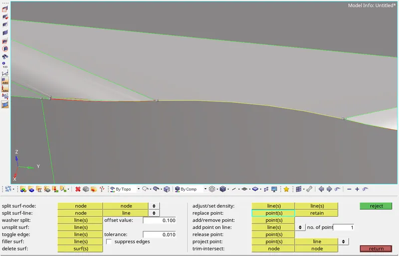
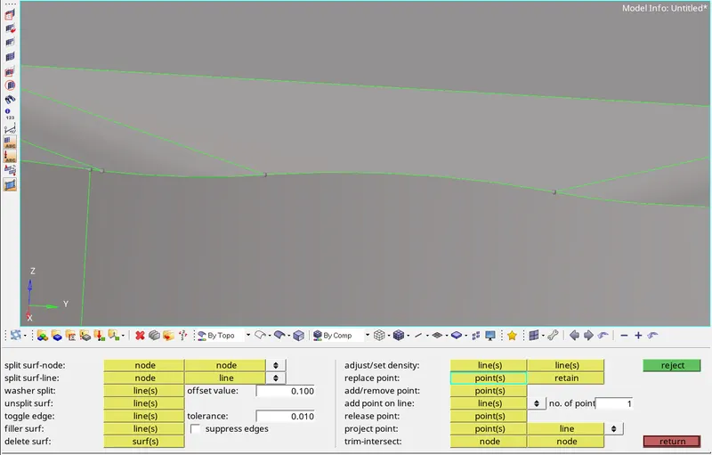
Fig 10: Removing duplicate surfaces
3) Mid surface extraction
First, the thickness of the floor panel is measured(F4>select two points). Since the given component is made of sheet metal and is of uniform thickness throughout, the midsurface is extracted through manual offsetting.
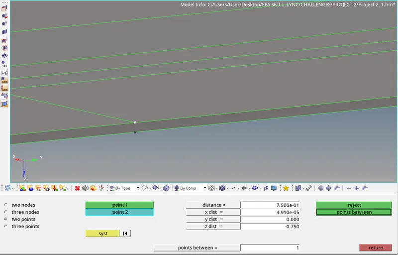
Fig 11: Measuring Thickness
Using the offset tool the outer surface of the floor panel is offset by a distance that is equal to half of, the distance measured between the outer and inner surfaces of the floor panel. (0.75/2 = 0.375mm )
(Geom>surface edit>offset>select 'surfs'>specify offset distance>offset)
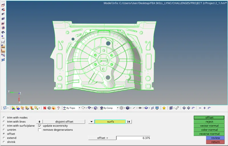
Fig 12: Manual offsetting of surface
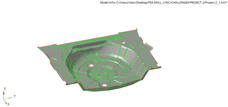
Fig 13: Extracted midsurface
After extracting the midsurface any defects on the extracted midsurface is rectified before starting the process of meshing. Also, for ensuring proper mesh flow and also for ease of meshing the surface is divided into sections and the meshing is carried out on each of the sections one by one.
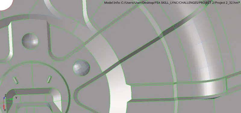
Fig 14: Performing geometry cleanup on the extracted midsurface
4) Meshing of midsurface
The given quality criterias need to be specified using the criteria file editor before meshing the model.
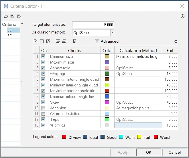
Fig 15: Criteria File Editor
Once the quality criterias are set, automeshing is performed with a target element size of 5.

Fig 16: Performing Automeshing
For regions that are symmetrical the elements can be reflected using the ‘reflect’ tool.
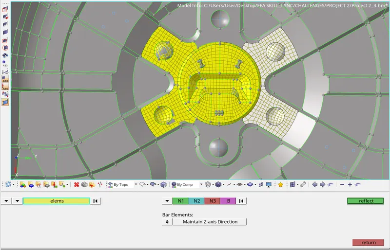
Fig 17: Reflecting Elements
5) Ensuring proper mesh flow and quality of elements generated
The generated mesh is examined properly to ensure that there is a proper mesh flow. Also, the number of trias should be kept to a minimum. Ensure that there are no rotating quads, back to back trias, opposite trias or trias on feature line.
Check if any elements are failing for any of the given quality criterias. If any element is found to be failing the given quality criteria then the cleanup tools are used to correct them.
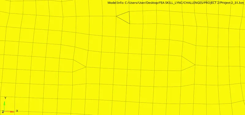
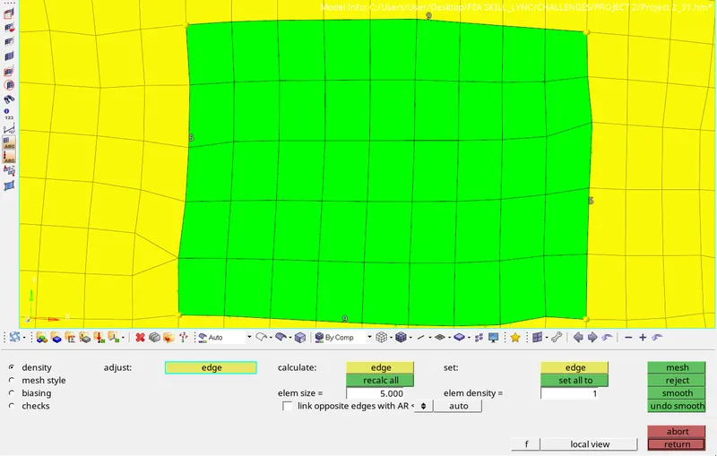
Fig 18: Removing Opposite Trias by Remeshing
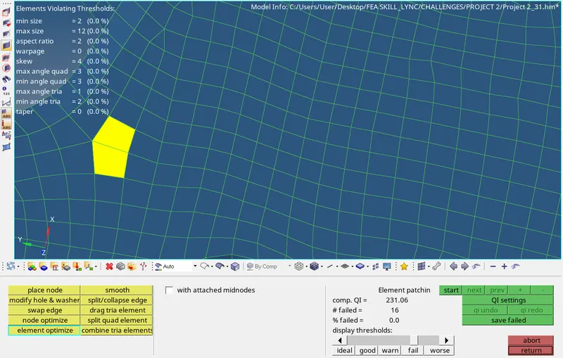
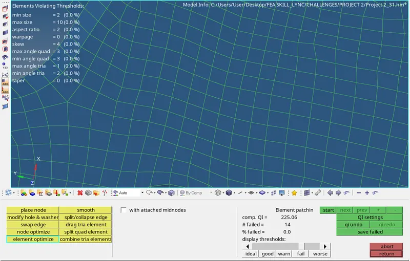
Fig 19: Using 'element optimize' tool
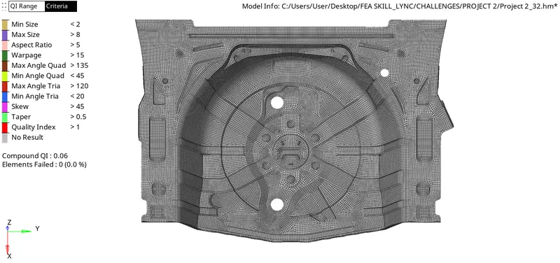
Fig 20: Quality Check
6) Checking Normals
Ensure that the normals are in the right direction.
(Tool>normals>displayed 2D elements>display)
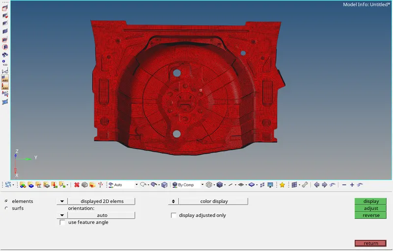
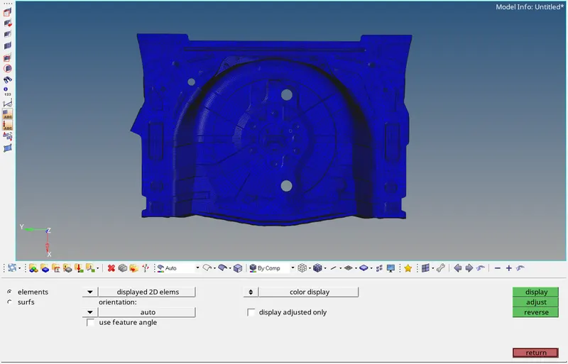
Fig 21: Checking normals
7) Assigning thickness
After meshing, the elements have to be assigned the measured thickness of the floor panel. For this, a ‘property’ has to be created. (Right click tab area>create>property)
Under the property menu the thickness ‘T’ has to be specified. Also, other properties like the material and card image can also be specified if needed.
To assign the property to the component, right click on the corresponding component and choose the ‘assign’ option. In the pop up menu select the corresponding property from the drop down list and apply.
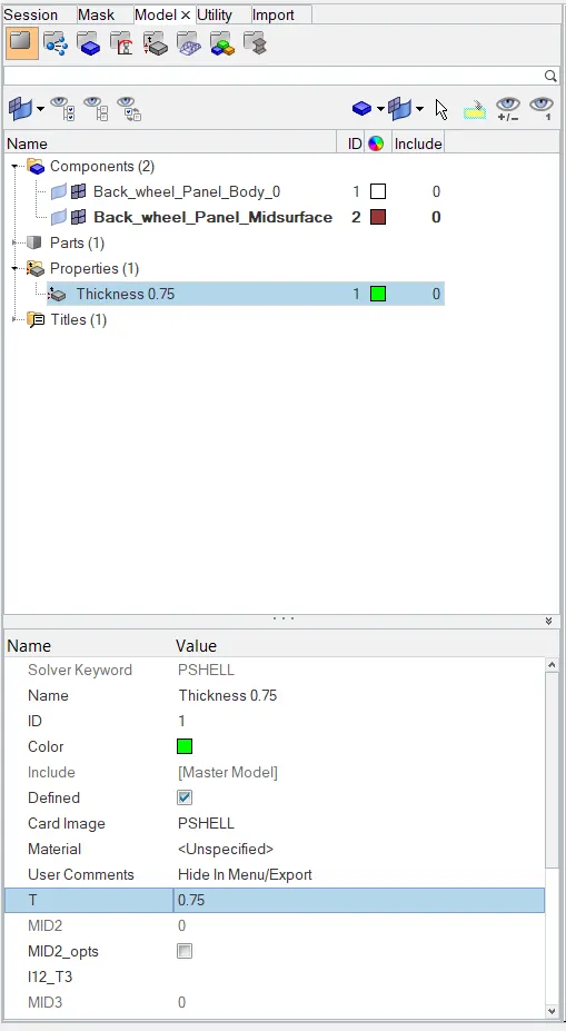
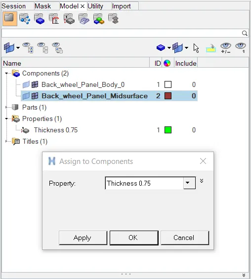
Fig 22: Creating Property and assigning thickness
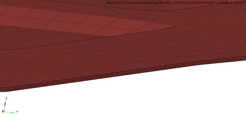
Fig 23: 2D Detailed Element Representation
FINAL MODEL IMAGE:
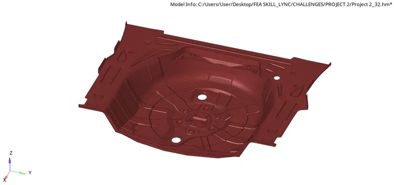
Fig 24: Isometric View
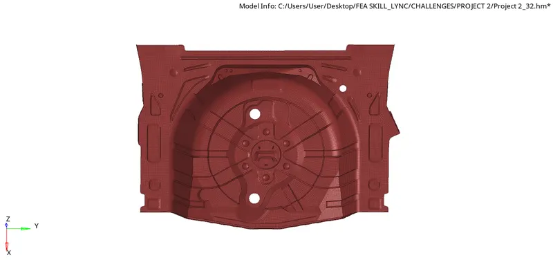
Fig 25: Front View
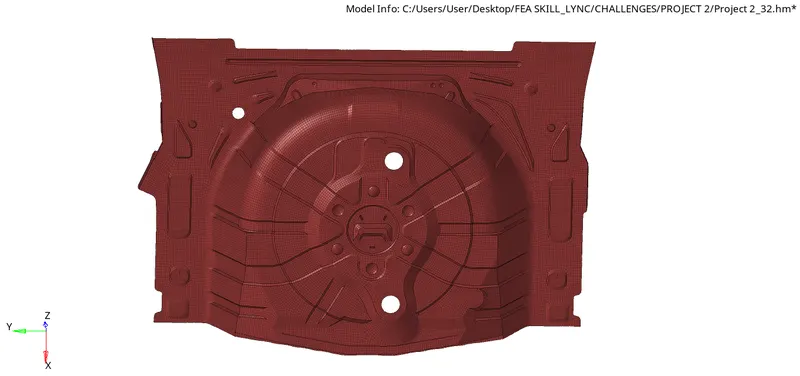
Fig 26: Rear View
CONCLUSION:
The given floor panel was meshed according to the given quality criterias after extracting the midsurface. Also, the required thickness was assigned to the elements.