Week - 4 - 2D meshing for Plastic components
OBJECTIVE:
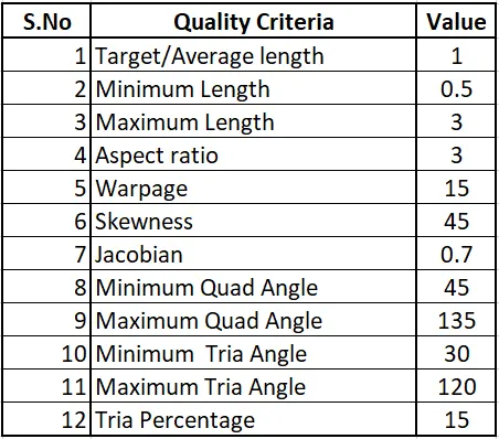
To perform 2D meshing on the given plastic component, after extracting the midsurface, by following the given Quality Criteria and to assign the corresponding thickness.
PROCEDURE:
1) Open the given model in ANSA.
2) Geometry Cleanup
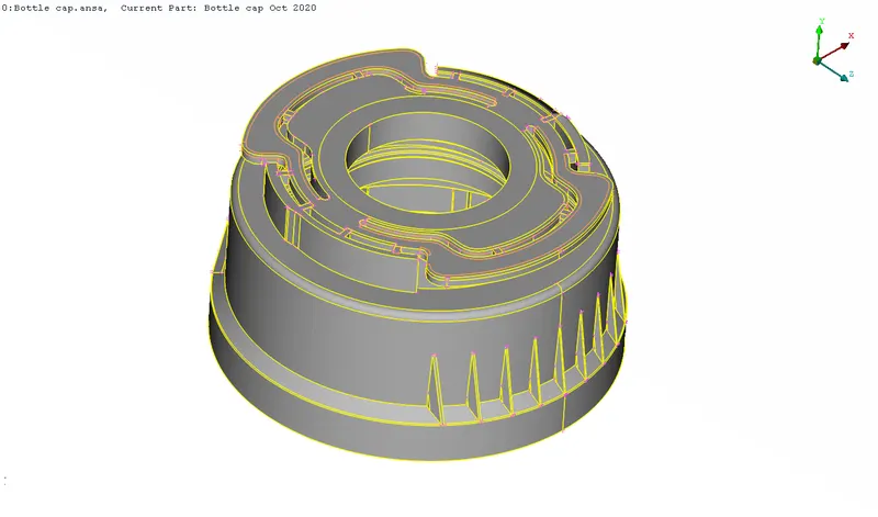
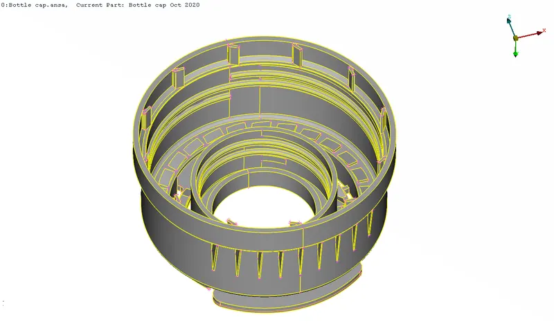
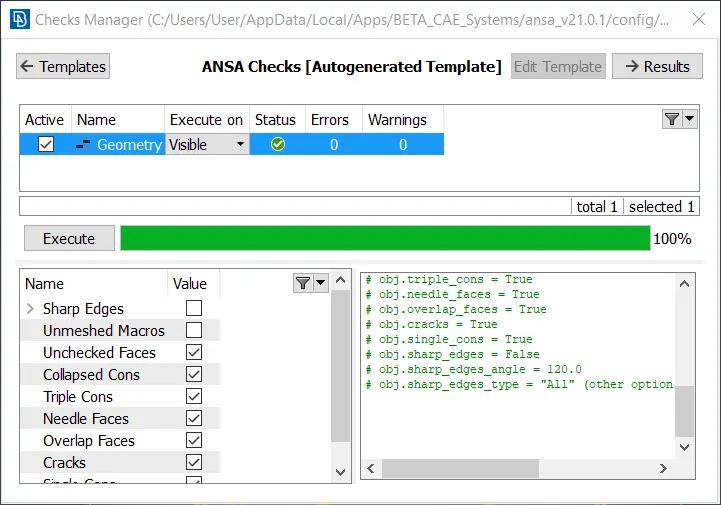
Before extracting the mid surface from the model, it needs to be ensured that the model surface is perfect and free from errors like free edges, cracks, overlap faces, distorted faces, needle faces etc. The geometry check is done using the Checks Manager available under, Tools>Checks>Geometry.
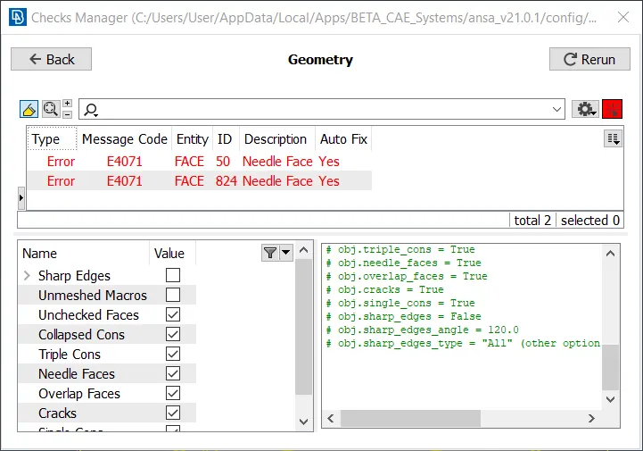
ANSA provides an option to automatically rectify the errors. This is done by, selecting all the errors>right click>Fix. If any errors persist then they can be fixed manually.
3) Mid surface extraction
The midsurface can be extracted either through manual midsurfacing or through auto midsurfacing. The type of method used depends on the geometry of the model.
For the given component most of the mid surfaces are extracted using manual offset as the geometry is complex and is of varying thickness. Under Faces>Offset, the top or bottom face is selected and it is then offset by a distance equal to half the thickness of the component.
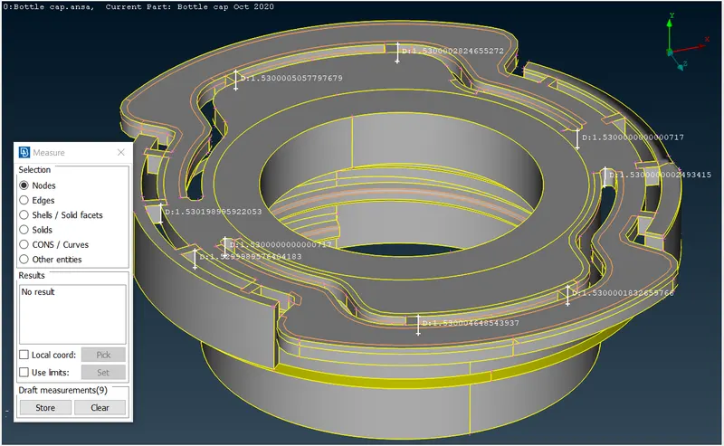
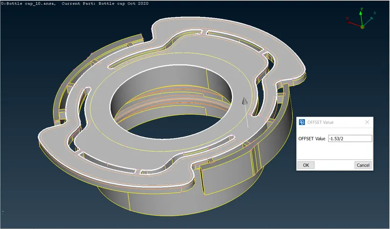
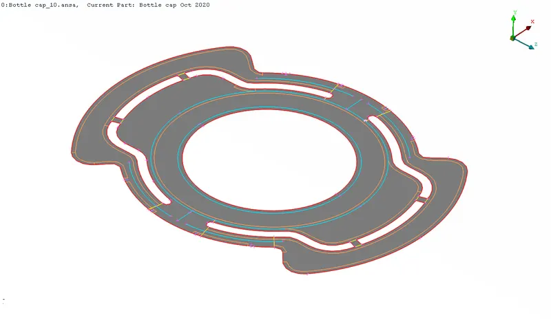
For other sections such as the rib which has a non-uniform thickness, the mid surface is extracted using the ‘middle’ tool.
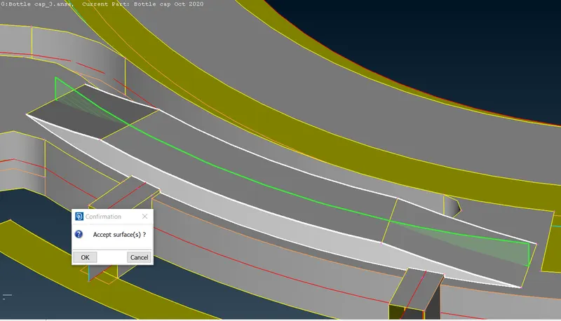
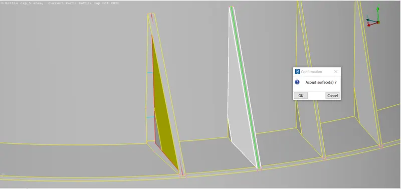
For the thread section, which has a trapezoid cross-section, the mid surface is extracted as follows. A curve is created in the middle of the top section by using Topo>Curves>middle option. This curve is then projected onto the base surface using CONS>Project tool. Then a surface is created between these two curves using the Faces>New>COONS option.
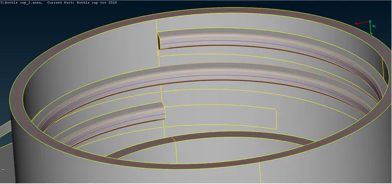
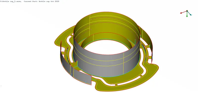
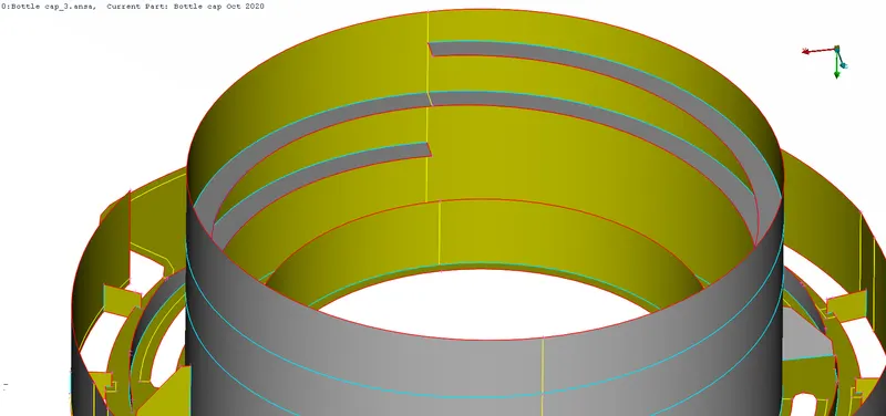
By using the Topo function topological conditions between selected adjacent CONS can be created automatically.
On the midsurface, if any lines are too close to each other or if the distance between the lines is less than the minimum element length, then one of the lines needs to be removed. Otherwise, on meshing, elements that fail the minimum element length criteria will be created between the closely spaced lines.
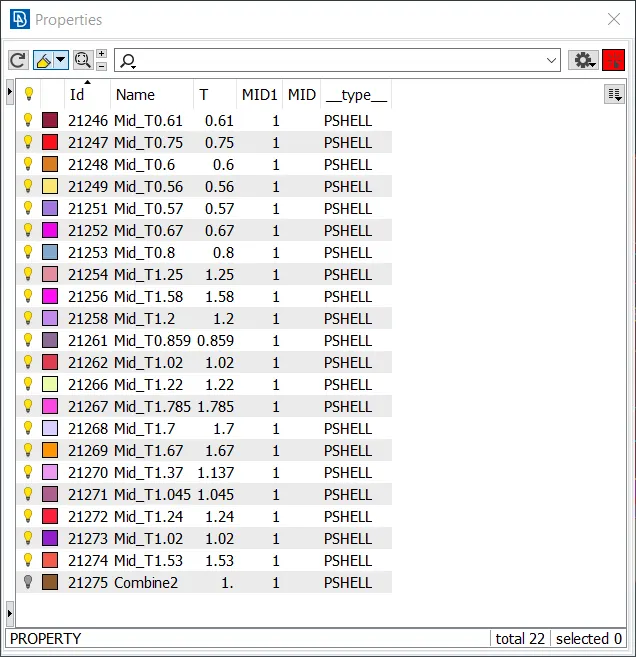
New PID’s are created for the mid surfaces and the corresponding thicknesses are assigned.
4) Meshing of midsurface
The meshing is performed using the ‘Best’ option under ‘Mesh Generation’. This function automatically meshes Macro Areas using all alternative meshing algorithms and keeps only the mesh of highest quality.
The given quality criteria’s need to be specified using the criteria file editor before meshing the model.
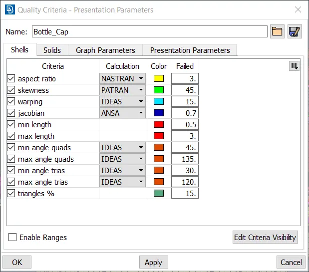
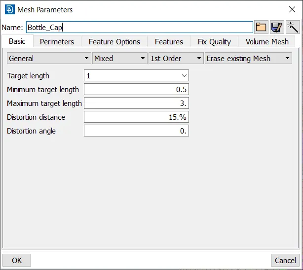
Once the quality criteria’s are set, meshing is performed with a target element size of 1 mm.
5) Ensuring proper mesh flow and quality of elements generated
The generated mesh is examined properly to ensure that there is a proper mesh flow. Also, the number of trias should be kept to a minimum. Ensure that there are no rotating quads, back to back trias, opposite trias or trias on feature line.
The various tools available such as Reconstruct, Split, Swap, and Paste can be used for this purpose.
Check if any elements are failing for any of the given quality criteria’s. If any element is found to be failing the given quality criteria then the required cleanup is done to correct them.
The ‘Reconstruct’ option under ‘Shell Mesh’ can be used to improve the mesh. It examines a given mesh and performs re-meshing to correct problematic areas and optimize the overall quality of the mesh according to the mesh parameters.
Smoothing is performed using the ‘Smooth’ option under Shell mesh to improve the mesh flow after performing any operation.
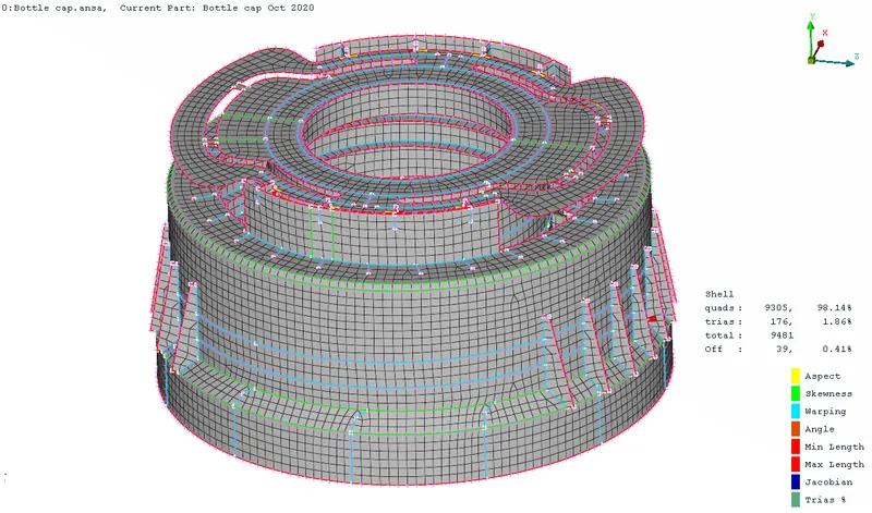
Some elements are failing for quality, but since these elements are needed to capture the features properly, they are kept as it is.
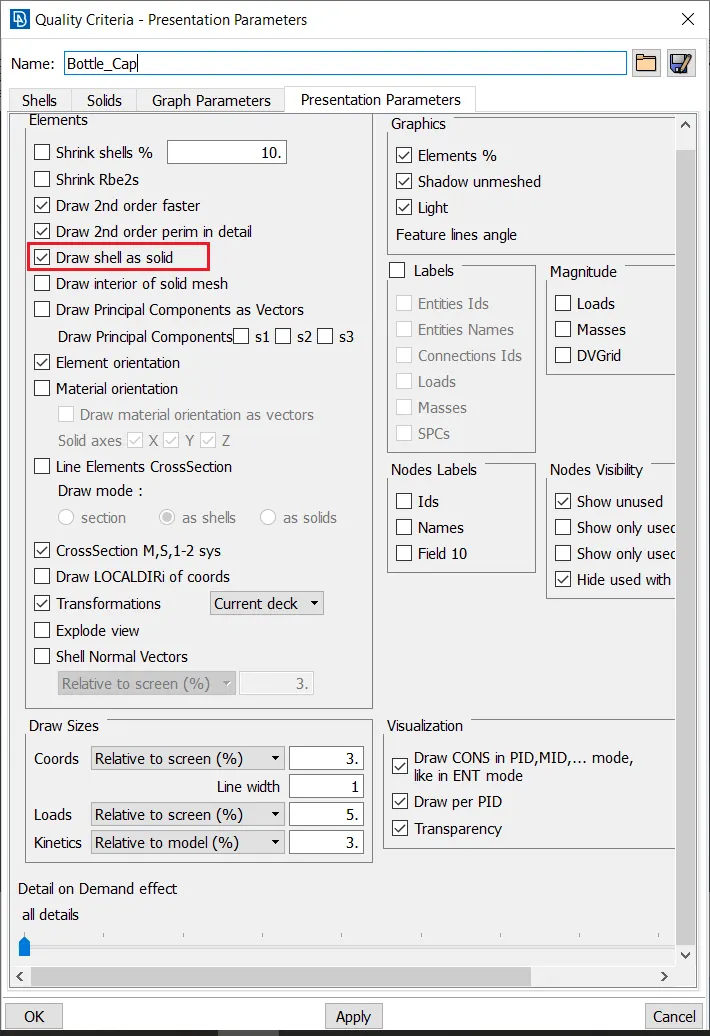
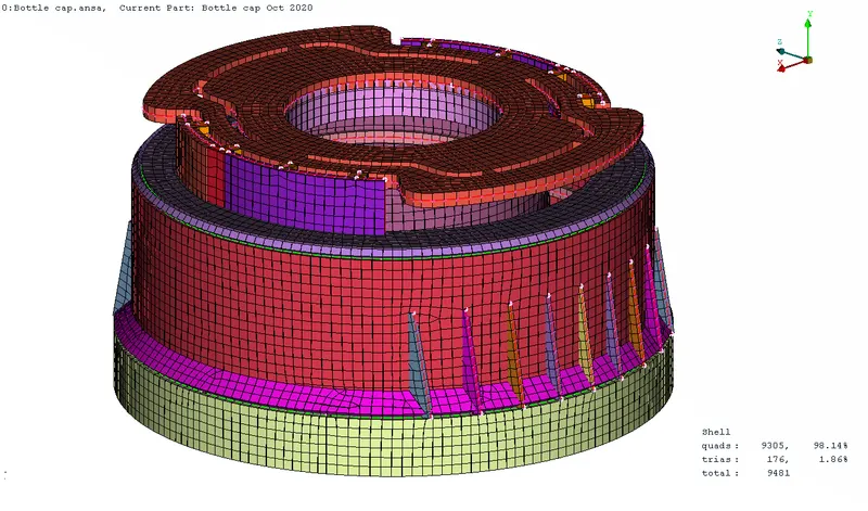
6) To view the 2D shell elements as solid based on their PID thickness,
Quality Criteria>Presentation Parameters>Draw shell as solid
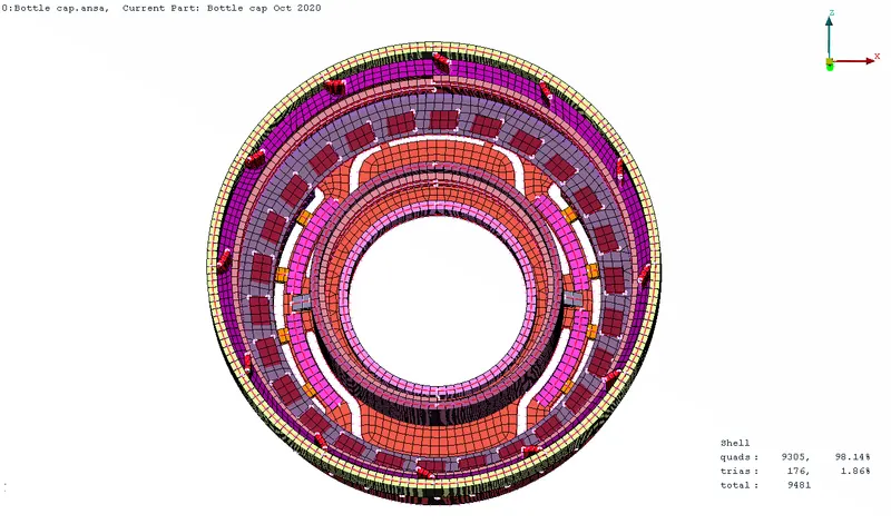
FINAL MESHED MODEL IMAGE:
LEARNING OUTCOMES:
- Learned how to perform geometry cleanup and extract midsurface for a plastic component having varying thickness.
- Gained understanding on how to perform meshing and obtain good quality mesh and proper mesh flow using the various tools available in ANSA pre-processor.
CONCLUSION:
The given components were meshed according to the given quality criteria’s after extracting the midsurface. Also, the required thickness was assigned to the elements.