Week 6 - Creating connection for Rear door
OBJECTIVE:
To create appropriate connections at the required locations on the given Rear door model.
PROCEDURE:
1) Open the given model in ANSA.
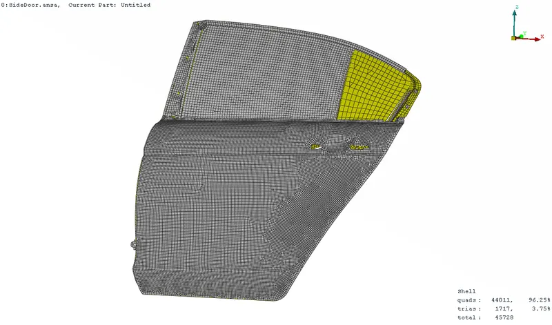
The entire model is found to be defined in a single PID.
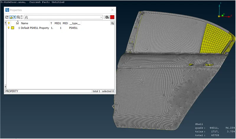
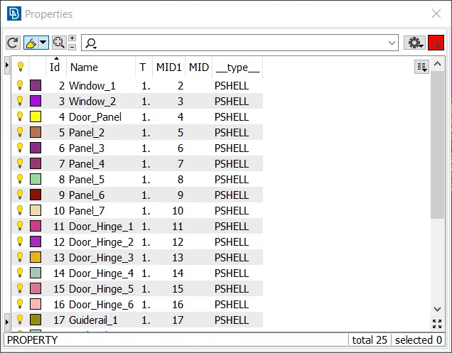
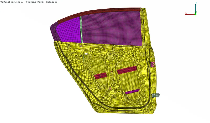
Hence, the different components are assigned to different PIDs using the ‘Set PID’ tool.
2) RBE2 Connection:
Rbe2 elements are used to establish a rigid connection at the required locations.
NASTRAN Deck>Elements>RBE2>Two Points/Many Points>Select the points
By selecting ‘Two Points’ the RBE2 element is created between only two nodes whereas by selecting ‘Many Points’ the RBE2 element can be created between many nodes.
Door Hinge:
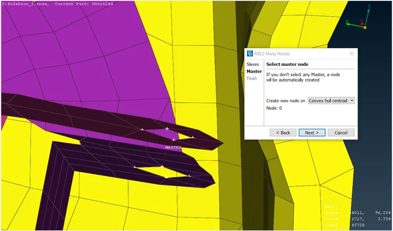
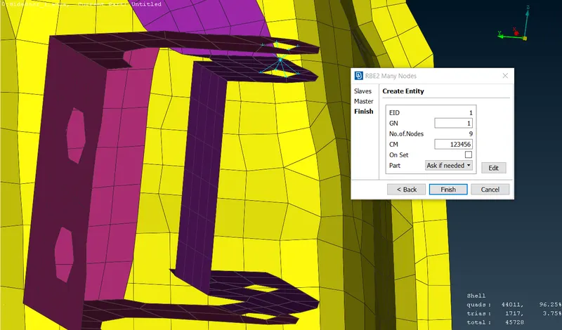
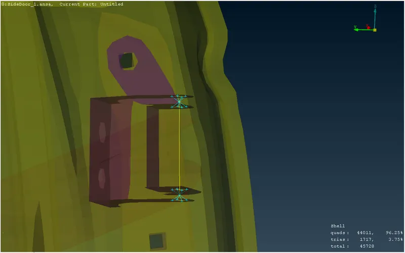
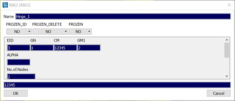
After creating RBE2 link at the door hinge, the DOF of the hinge should be allowed in the rotational Z axis to represent the opening and closing of the door. All the other DOFs are arrested. (CM value changed to 12345)
Door Handle:
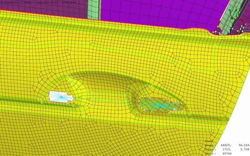
For the door handle, after creating the RBE2 elements at its location, the mass of the door handle is added at the COG (represented by the center of the Two Point RBE2 element). The mass is specified in Tonnes. (100 gm = 0.0001 Tonne)
NASTRAN Deck>Elements>CONMI>CONM2
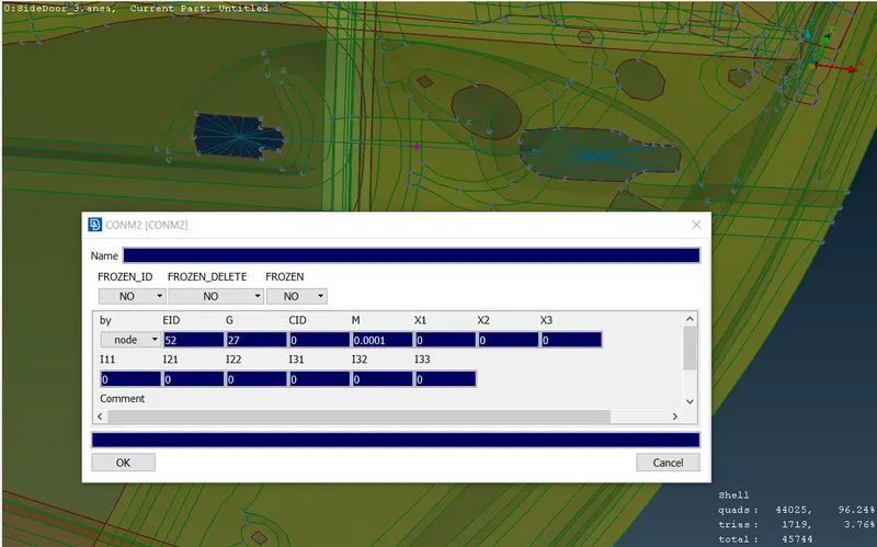
3) Bolt Connection:
To represent a bolt connection, initially, a point is created at the COG of the bolt hole.
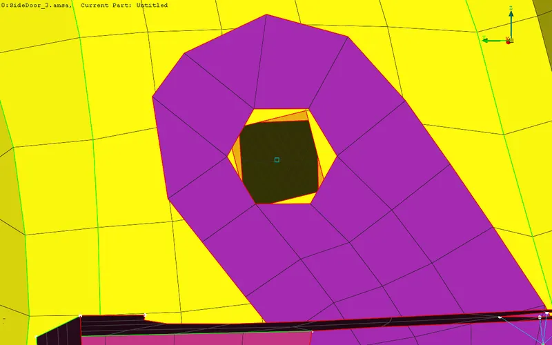
The 3D point is then converted into a Bolt point.
Assembly>Convert>3D Points>Bolt
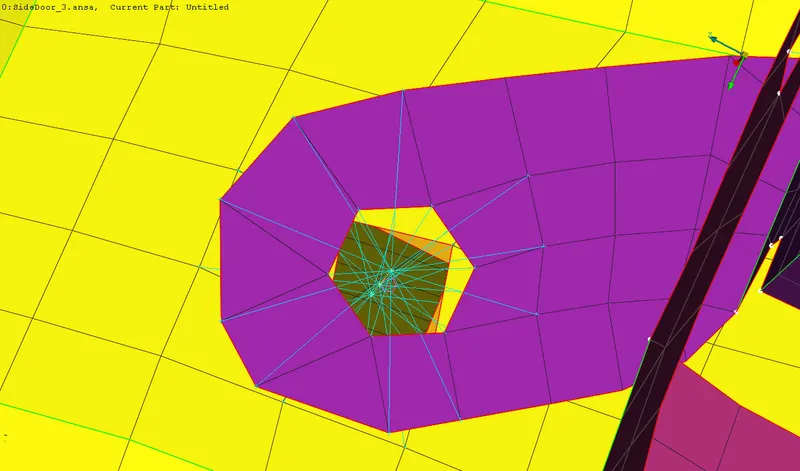
Then the connection manager is opened and the Bolt point is selected. The parts to be connected by the bolts are assigned to P1, P2, P3 and P4 respectively, depending on the number of parts present to be joined. Select the FE Rep Type as Bolt and define the properties.
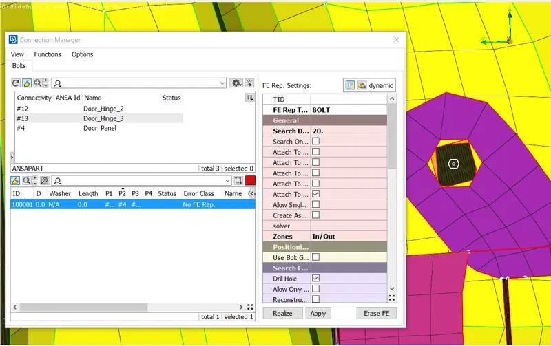
Click on ‘Apply’ and then ‘Realize’ the connection.
4) Spotweld Connection:
To establish a spotweld connection, first, a COG point is created. The 3D point is then converted into a Spotweld Point.
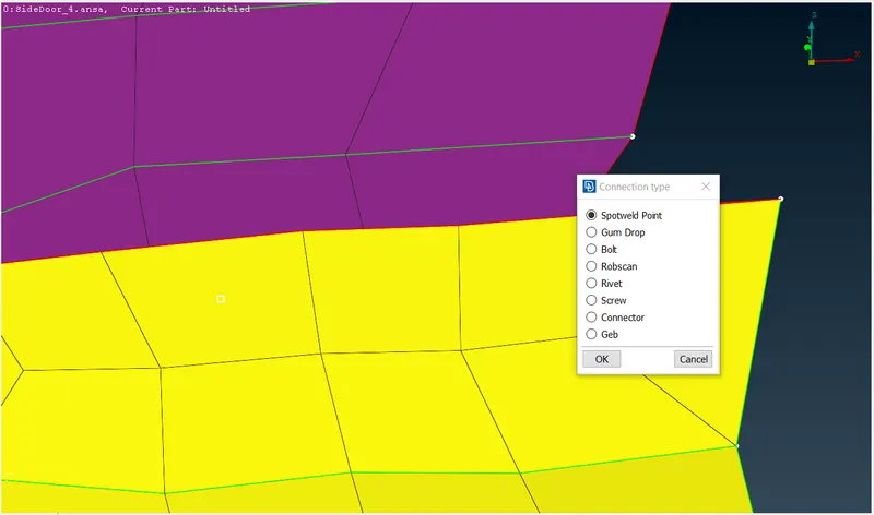
Then the connection manager is opened and the Spotweld point is selected. The parts to be joined are selected under P1 and P2. Select the FE Rep Type as RBE3-HEXA-RBE3 and define the properties.
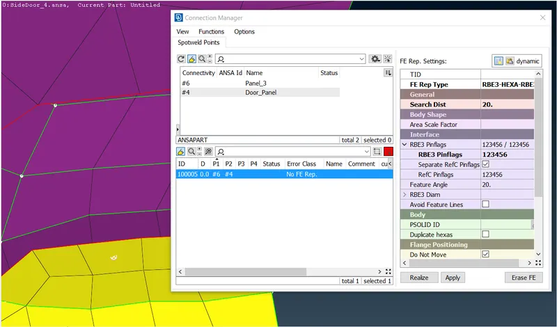
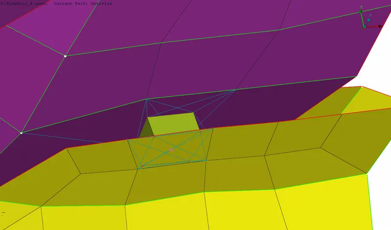
Click on ‘Apply’ and then ‘Realize’ the connection.
5) Seamweld Connection:
To create the Seamweld, a curve has to be created. This is done by using, Mesh>Perimeters>Feat2Curv.
The curve is then converted into a Seam Line.
Assembly>Convert>Curves>Seam Line
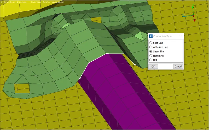
Then the connection manager is opened and the Seam Line is selected. The parts to be joined are selected under P1 and P2. Since the parts to be joined are parallel to each other, the FE Rep Type selected is ‘OVERLAP SHELL’ and the properties are defined. If the parts to be joined are perpendicular to each other then, ‘Y-JOINT-SHELL’ is selected as the FE Rep Type.
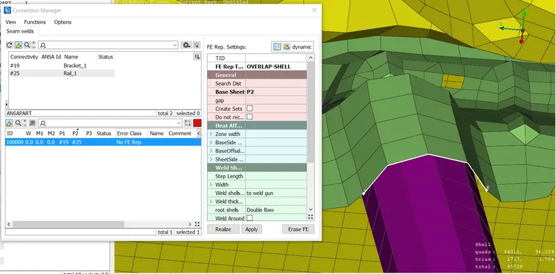
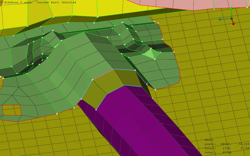
Click on ‘Apply’ and then ‘Realize’ the connection.
6) CBUSH Connection:
To establish a CBUSH connection for the door window, the following steps are carried out. First, curves are created from the window edges using the ‘Feat2Curv’ tool. The bottom curve is then offset by a certain distance so as to aid in establishing a connection on both sides of the window.
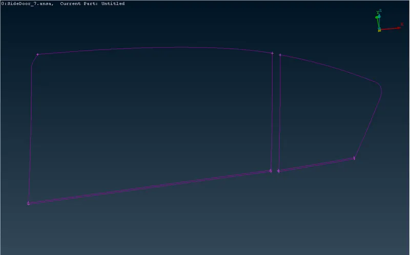
The curves are then converted to ‘Spot Line’.
Assembly>Convert>Curves>Spot Line
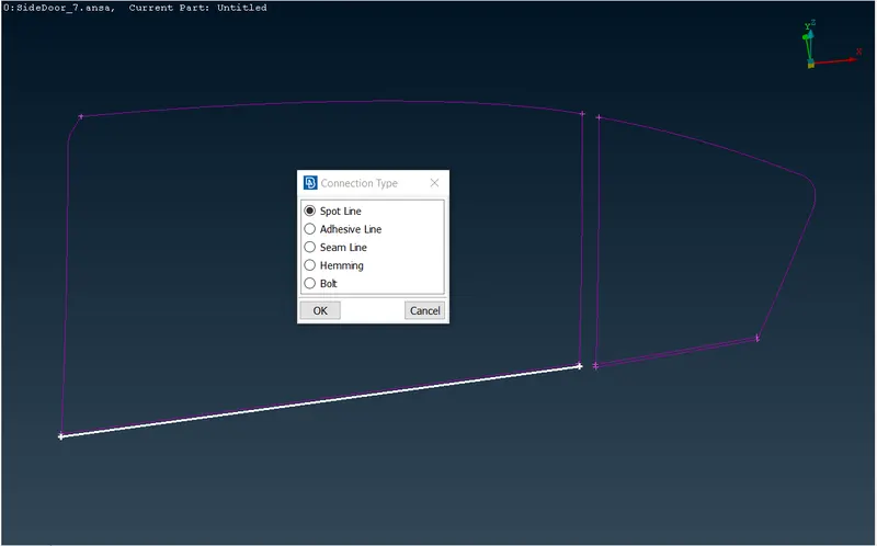
Then the connection manager is opened and the Spot Line is selected. The parts to be joined are selected under P1 and P2. Select the FE Rep Type as RBE3-CBUSH-RBE3 and define the properties.
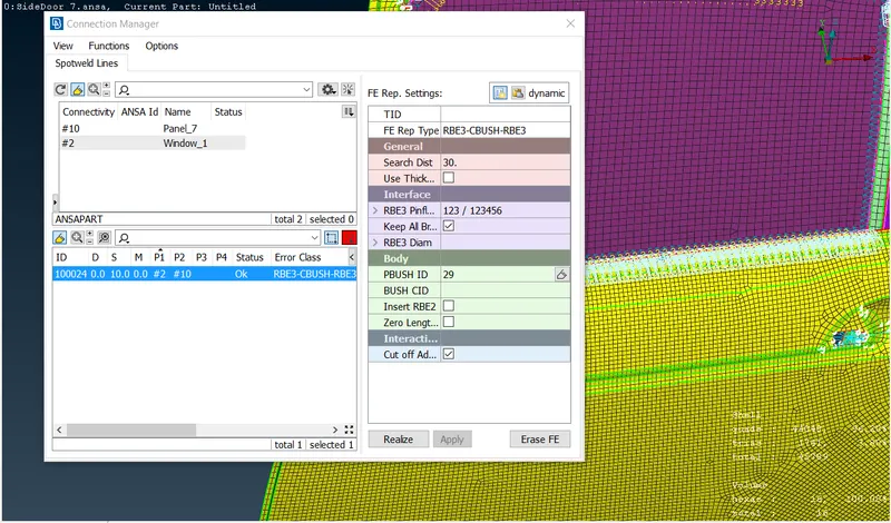
Under ‘PBUSH ID’, the stiffness values of the PBUSH elements can be defined.
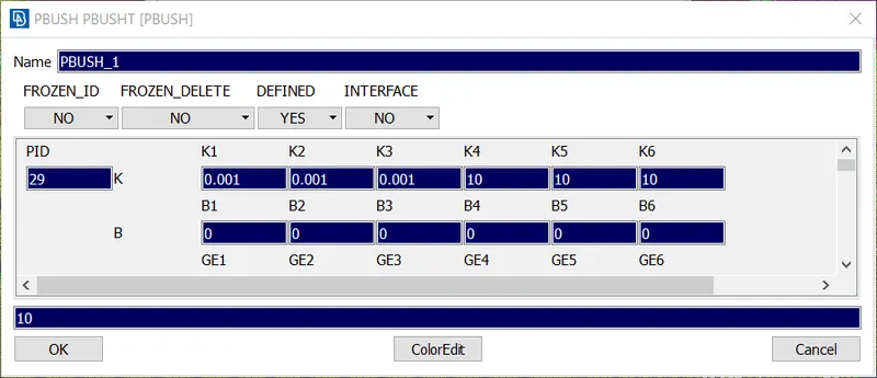
Click on ‘Apply’ and then ‘Realize’ the connection.
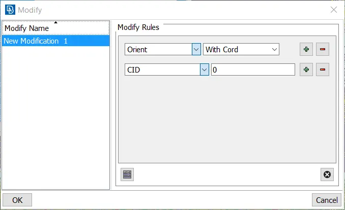
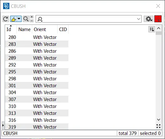
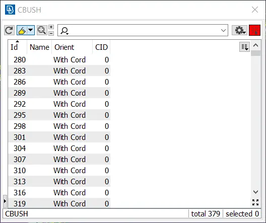
The PBUSH elements are by default oriented as per the local coordinate system. The orientation is changed from the local coordinate system to the global coordinate system.
Database>Elements>CBUSH>Select all>Right Click>Modify>Orient-With Cord>CID-0
FINAL MODEL IMAGE:
LEARNING OUTCOMES:
- Gained understanding of the different types of connections available in ANSA and where to deploy them.
- Learned how to implement connections such as Rbe2(rigid), Bolt, Seam Weld, Spot Weld, and CBUSH.
CONCLUSION:
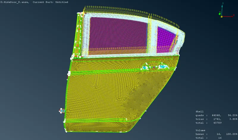
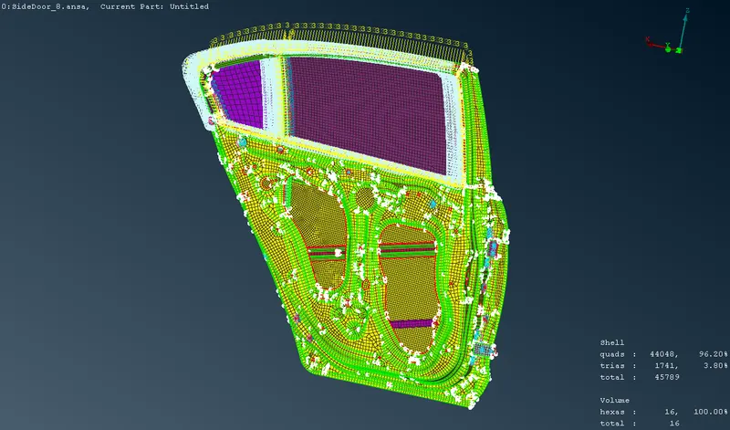
Appropriate connections were deployed at the necessary locations on the given Rear door model.